Download as PDF, PPTX


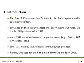
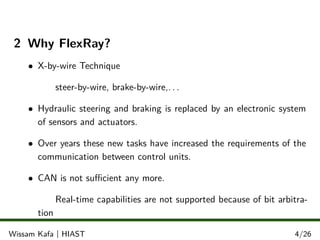
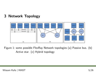
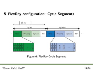
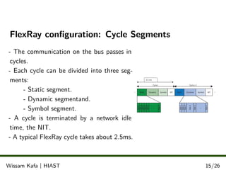
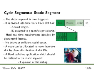
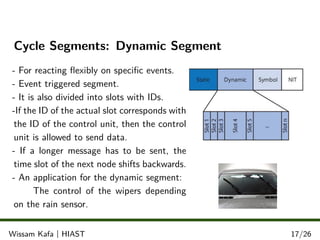


This document discusses the FlexRay protocol. It was developed for automotive applications as CAN was insufficient for new electronic systems with real-time requirements. FlexRay supports higher data rates, flexible topologies, and fault tolerance. It divides communication into static and dynamic segments for hard and soft real-time messages. Nodes synchronize clocks to support time-critical applications. FlexRay enables next-generation in-car control systems with speeds up to 20Mbps.