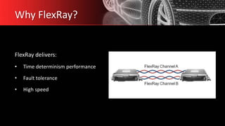
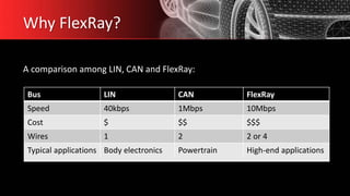
The FLEXRAY Protocol
By Roja Ramani Pradhan (ESD-BEG)
• Introduction
• Why FlexRay?
• Network topology
• Structure of a FlexRay node
• The communication cycle
• Applications
• Conclusion
Introduction
The FlexRay Consortium was made up of the following core members:
• Freescale Semiconductor
• Robert Bosch GmbH
• NXP Semiconductors
• BMW AG
• Volkswagen AG
• Daimler AG
• General Motors
2007-2008 BMW X5 photographed in Gainesville, Virginia, USA.
Why FlexRay?
FlexRay delivers:
• Time determinism performance
• Fault tolerance
• High speed
Why FlexRay?
Bus LIN CAN FlexRay
Speed 40kbps 1Mbps 10Mbps
Cost $ $$ $$$
Wires 1 2 2 or 4
Typical applications Body electronics Powertrain High-end applications
A comparison among LIN, CAN and FlexRay:
Why FlexRay?
Many aspects of FlexRay are designed to keep costs down while delivering
top performance in a rugged environment.
• FlexRay uses unshielded twisted pair cabling.
• FlexRay supports single and dual-channel configurations.
• Most first-generation FlexRay networks only utilize one channel to keep wiring costs
down
Why FlexRay?
Bus Level
Emissions are limited by the relatively low differential voltages. (Differential signaling
between Bus Plus (BP) and Bus Minus(BM))
• 2V for data_1
• -2V for data_0
Cabling impedance is 80-110Ω
as FlexRay specifies a load of
40-55 Ω
Network topology
FlexRay supports
• Simple multi-drop passive connections
• Active star connections (for complex networks)
Multi-drop bus Star network
Network topology
Future FlexRay networks will likely consist of hybrid networks i.e. the combination of bus
and star topology.
Hybrid network
Bus topology
(Ease of use, cost advantages)
Star topology
(Performance, reliability)
Hybrid network
Structure of a FlexRay node
Controller part
• Host CPU
• Communication controller
Driver part
• Bus guardian
• Bus driver
Structure of a FlexRay node
Communication Controller (FlexRay Controller)
• Framing
• Bus access
• Error detection and handling
• Synchronization
• Puts the FlexRay bus to sleep and wakes it up
• Codes TX messages and decodes RX messages.
Structure of a FlexRay node
FlexRay node with stand-alone FlexRay controller
FlexRay node with integrated FlexRay controller
Structure of a FlexRay node
Bus Guardian
• Prevents disharmony caused by unauthorized transmissions within time slots not
assigned to the nodes.
• Only allows the Bus Driver to place data received from the FlexRay controller on
the bus, if it conforms to the communication schedule.
Structure of a FlexRay node
Bus Driver (FlexRay transceiver)
• Couples the FlexRay controller to the physical transmission medium
• Signal transformation- It transforms the logical signal stream received by
the FlexRay controller into a physical signal stream and transforms the received
physical signal stream into a logical signal stream.
The Communication Cycle
• The duration of a cycle is fixed when
the network is designed.
• The duration is typically 1-5ms.
• A communication cycle is made up
of a defined number of macroticks
and the macroticks are composed of
a number of microticks, the smallest
time unit of the local clocks.
• Macroticks are often 1µs long.
The Communication Cycle
Static Segment
The Communication Cycle
Static Segment
• This is the space in the cycle dedicated to scheduling a no. of time-triggered frames.
• This segment is broken up into slots, each slot containing a reserved frame of data.
• When each slot occurs in time, the reserved ECU has the opportunity to transmit its
data into that slot.
• Once the time passes, the ECU must wait until the next cycle to transmit its data in that
slot.
• If an ECU goes offline or decides not to transmit data, its slot remains open and is not
used by any other ECU.
The Communication Cycle
Dynamic Segment
The Communication Cycle
Dynamic Segment
• It serves to transmit event driven messages.
• It always exhibits the same length.
• Minislots are pre-assigned to each frame of data that is eligible for transmission.
• Once a minislot occurs, an ECU has a brief opportunity to broadcast its frame.
• If it doesn’t broadcast, it loses its spot in the dynamic frame and the next minislot occurs.
• A minislot is typically a Macrotick (1µs) long.
The Communication Cycle
Symbol Window
• The symbol window serves to transmit symbols.
• The collision avoidance symbol is used to indicate the start of the first
communication cycle to a FlexRay node.
• The media test symbol is used for testing of a bus guardian.
• The wake-up symbol is used for waking up the FlexRay cluster.
The Communication Cycle
Network Idle Time
• It is a pre-defined known length by ECUs.
• The part of time-base correction is performed during the network idle time.
• The ECUS make use of this idle time to make adjustments for any drift that may
have occurred during the previous cycle.
The Communication Cycle
Frame Format
Each slot of static or dynamic segment is divided into 3 segments.
• Header
• Payload
• Trailer
The Communication Cycle
Header
It is 5 bytes (40 bits) long.
• Status bits - 5 bits
• Frame ID – 11 bits
• Payload length – 7 bits
• Header CRC – 11 bits
• Cycle count – 6 bits
The Communication Cycle
Payload
It is upto 127 words (254 bytes)
long.
It contains the actual data
transferred by the frame.
The length is over 30 times
greater than CAN.
The Communication Cycle
Trailer
It contains 3 8-bit CRCs to detect errors
Applications
• Recent introductions indicate that automakers have a definitive FlexRay rollout plan.
And, BMW is ahead in this race with the implementation of FlexRay v2.1 for active
damping control.
• Although, initially envisioned as an enabling technology for automotive X-by-wire
(drive-by-wire, steer-by-wire) applications, it is now being adopted for other
applications like improving manufacturing efficiencies, safety regulations and the
convenience features. This technology is being enabled by integrated complex
microcontrollers and transceivers.
Conclusion
• FlexRay focuses on a set of core needs for today’s automotive industry, including
higher data rates than previous standards, flexible data communications, versatile
topology options, and fault-tolerant operation.
• FlexRay thus delivers the speed and reliability required for next-generation in-car
control systems.
1. https://en.wikipedia.org/wiki/FlexRay
2. https://www.ni.com/en-gb/innovations/white-papers/06/flexray-automotive-
communication-bus-overview.html
3. https://automotivetechis.wordpress.com/flexray/
4. https://svn.ipd.kit.edu/nlrp/public/FlexRay/FlexRay%E2%84%A2%20Protocol%20S
pecification%20Version%203.0.1.pdf
References
FlexRay

FlexRay

  • 1.
    The FLEXRAY Protocol ByRoja Ramani Pradhan (ESD-BEG)
  • 2.
    • Introduction • WhyFlexRay? • Network topology • Structure of a FlexRay node • The communication cycle • Applications • Conclusion
  • 3.
    Introduction The FlexRay Consortiumwas made up of the following core members: • Freescale Semiconductor • Robert Bosch GmbH • NXP Semiconductors • BMW AG • Volkswagen AG • Daimler AG • General Motors 2007-2008 BMW X5 photographed in Gainesville, Virginia, USA.
  • 4.
    Why FlexRay? FlexRay delivers: •Time determinism performance • Fault tolerance • High speed
  • 5.
    Why FlexRay? Bus LINCAN FlexRay Speed 40kbps 1Mbps 10Mbps Cost $ $$ $$$ Wires 1 2 2 or 4 Typical applications Body electronics Powertrain High-end applications A comparison among LIN, CAN and FlexRay:
  • 6.
    Why FlexRay? Many aspectsof FlexRay are designed to keep costs down while delivering top performance in a rugged environment. • FlexRay uses unshielded twisted pair cabling. • FlexRay supports single and dual-channel configurations. • Most first-generation FlexRay networks only utilize one channel to keep wiring costs down
  • 7.
    Why FlexRay? Bus Level Emissionsare limited by the relatively low differential voltages. (Differential signaling between Bus Plus (BP) and Bus Minus(BM)) • 2V for data_1 • -2V for data_0 Cabling impedance is 80-110Ω as FlexRay specifies a load of 40-55 Ω
  • 8.
    Network topology FlexRay supports •Simple multi-drop passive connections • Active star connections (for complex networks) Multi-drop bus Star network
  • 9.
    Network topology Future FlexRaynetworks will likely consist of hybrid networks i.e. the combination of bus and star topology. Hybrid network Bus topology (Ease of use, cost advantages) Star topology (Performance, reliability) Hybrid network
  • 10.
    Structure of aFlexRay node Controller part • Host CPU • Communication controller Driver part • Bus guardian • Bus driver
  • 11.
    Structure of aFlexRay node Communication Controller (FlexRay Controller) • Framing • Bus access • Error detection and handling • Synchronization • Puts the FlexRay bus to sleep and wakes it up • Codes TX messages and decodes RX messages.
  • 12.
    Structure of aFlexRay node FlexRay node with stand-alone FlexRay controller FlexRay node with integrated FlexRay controller
  • 13.
    Structure of aFlexRay node Bus Guardian • Prevents disharmony caused by unauthorized transmissions within time slots not assigned to the nodes. • Only allows the Bus Driver to place data received from the FlexRay controller on the bus, if it conforms to the communication schedule.
  • 14.
    Structure of aFlexRay node Bus Driver (FlexRay transceiver) • Couples the FlexRay controller to the physical transmission medium • Signal transformation- It transforms the logical signal stream received by the FlexRay controller into a physical signal stream and transforms the received physical signal stream into a logical signal stream.
  • 15.
    The Communication Cycle •The duration of a cycle is fixed when the network is designed. • The duration is typically 1-5ms. • A communication cycle is made up of a defined number of macroticks and the macroticks are composed of a number of microticks, the smallest time unit of the local clocks. • Macroticks are often 1µs long.
  • 16.
  • 17.
    The Communication Cycle StaticSegment • This is the space in the cycle dedicated to scheduling a no. of time-triggered frames. • This segment is broken up into slots, each slot containing a reserved frame of data. • When each slot occurs in time, the reserved ECU has the opportunity to transmit its data into that slot. • Once the time passes, the ECU must wait until the next cycle to transmit its data in that slot. • If an ECU goes offline or decides not to transmit data, its slot remains open and is not used by any other ECU.
  • 18.
  • 19.
    The Communication Cycle DynamicSegment • It serves to transmit event driven messages. • It always exhibits the same length. • Minislots are pre-assigned to each frame of data that is eligible for transmission. • Once a minislot occurs, an ECU has a brief opportunity to broadcast its frame. • If it doesn’t broadcast, it loses its spot in the dynamic frame and the next minislot occurs. • A minislot is typically a Macrotick (1µs) long.
  • 20.
    The Communication Cycle SymbolWindow • The symbol window serves to transmit symbols. • The collision avoidance symbol is used to indicate the start of the first communication cycle to a FlexRay node. • The media test symbol is used for testing of a bus guardian. • The wake-up symbol is used for waking up the FlexRay cluster.
  • 21.
    The Communication Cycle NetworkIdle Time • It is a pre-defined known length by ECUs. • The part of time-base correction is performed during the network idle time. • The ECUS make use of this idle time to make adjustments for any drift that may have occurred during the previous cycle.
  • 22.
    The Communication Cycle FrameFormat Each slot of static or dynamic segment is divided into 3 segments. • Header • Payload • Trailer
  • 23.
    The Communication Cycle Header Itis 5 bytes (40 bits) long. • Status bits - 5 bits • Frame ID – 11 bits • Payload length – 7 bits • Header CRC – 11 bits • Cycle count – 6 bits
  • 24.
    The Communication Cycle Payload Itis upto 127 words (254 bytes) long. It contains the actual data transferred by the frame. The length is over 30 times greater than CAN.
  • 25.
    The Communication Cycle Trailer Itcontains 3 8-bit CRCs to detect errors
  • 26.
    Applications • Recent introductionsindicate that automakers have a definitive FlexRay rollout plan. And, BMW is ahead in this race with the implementation of FlexRay v2.1 for active damping control. • Although, initially envisioned as an enabling technology for automotive X-by-wire (drive-by-wire, steer-by-wire) applications, it is now being adopted for other applications like improving manufacturing efficiencies, safety regulations and the convenience features. This technology is being enabled by integrated complex microcontrollers and transceivers.
  • 27.
    Conclusion • FlexRay focuseson a set of core needs for today’s automotive industry, including higher data rates than previous standards, flexible data communications, versatile topology options, and fault-tolerant operation. • FlexRay thus delivers the speed and reliability required for next-generation in-car control systems.
  • 28.
    1. https://en.wikipedia.org/wiki/FlexRay 2. https://www.ni.com/en-gb/innovations/white-papers/06/flexray-automotive- communication-bus-overview.html 3.https://automotivetechis.wordpress.com/flexray/ 4. https://svn.ipd.kit.edu/nlrp/public/FlexRay/FlexRay%E2%84%A2%20Protocol%20S pecification%20Version%203.0.1.pdf References

Editor's Notes

  • #4 By September 2009, there were 28 premium associate and more than 60 associate members. At the end of 2009, the consortium disbanded. The first series production vehicle with FlexRay was at the end of 2006 in the BMW X5, enabling a new and adaptive damping system. Full use of FlexRay was introduced in 2008 in the new BMW 7 series.
  • #6 In order to optimize cost and reduce transition challenges, the next generation automobiles will contain FlexRay for high-end applications CAN for mainstream powertrain communications LIN for low cost body electronics
  • #9 Multi-drop bus topology is used by CAN and LIN and is familiar with OEMs. In Star network, individual nodes are connected to a central active node. It runs over longer distances and is more reliable if a portion of the network fails.
  • #13 Integrated FlexRay controller is a peripheral module of a host. The advantage is simpler and quicker communication between the Host and the FlexRay controller. This solution lacks flexibility. Flexibility is attained when the FlexRay controller is constructed to be separate from the Host. This is called a Stand-alone FlexRay Controller.
  • #16 The communication cycle is composed of at least two time segments. Static segment and Network Idle Time (NIT). Optionally, the communication cycle may be extended by adding the Dynamic segment and a symbol window.
  • #19 It serves to transmit event driven messages. It always exhibits the same length. Minislots are pre-assigned to each frame of data that is eligible for transmission. Once a minislot occurs, an ECU has a brief opportunity to broadcast its frame. If it doesn’t broadcast, it loses its spot in the dynamic frame and the next minislot occurs. A minislot is typically a Macrotick (1µs) long.
  • #24 The Frame ID defines the slot in which the frame should be transmitted and is used for prioritizing event-triggered frames. The Payload Length contains the number of words which are transferred in the frame. The Header CRC is used to detect errors during the transfer. The Cycle Count contains the value of a counter that advances incrementally each time a Communication Cycle starts.