W E LL S E R V I C E S
W E L L S E R V I C E S
Coiled Tubing Drilling
Services
2.
2
Outline
• Training Objectives
•Introduction
• Advantages , Limitations and Main Concepts
• Main CTD Applications
• Over vs Under-balance
• Surface Equipment
• Downhole Equipment
• Fluid Requirements
• Technical Overview – Well Example
• Design Considerations
3.
3
Objectives
• Identify thedifferences between CT Drilling and conventional
drilling.
• Identify advantages and limitations of CTD.
• Point out the main CTD applications.
• Identify types of CTD bottomhole assemblies and their functions.
• Identify types of surface equipment needed for CTD.
• Recognize CTD fluids requirements.
• Identify integrated service opportunities that can be provided by
Schlumberger.
• Identify factors that must be controlled when designing a CTD job.
4.
4
Outline
• Training Objectives
•Introduction
• Advantages and Limitations and Main
Concepts
• Main CTD Applications
• Over vs Under-balance
• Surface Equipment
• Downhole Equipment
• Fluid Requirements
• Technical Overview – Well Example
• Design Considerations
5.
5
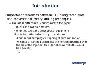
Introduction
• Important differencesbetween CT Drilling techniques
and conventional (rotary) drilling techniques.
– The main difference : cannot rotate the pipe :
– must use downhole motors,
– orienting tools and other special equipment
How to focus the balance of pros and cons :
-Continuous pumping vs stopping at each connection
-Weight : CT can be pushed into the horizontal section with
the aid of the Injector Head . (on shallow wells this could
be a benefit)
- …
6.
6
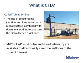
What is CTD?
CoiledTubing Drilling
• The use of coiled tubing
(continuous pipe), stored on a
reel at surface, combined with
downhole mud motors to turn
the bit to deepen a wellbore.
• MWD / LWD mud pulse and wired telemetry are
available to directionally steer the wellbore to the
zone of interest.
7.
7
Outline
• Training Objectives
•Introduction
• Advantages , Limitations and Main Concepts
• Main CTD Applications
• Over vs Under-balance
• Surface Equipment
• Downhole Equipment
• Fluid Requirements
• Technical Overview – Well Example
• Design Considerations
8.
8
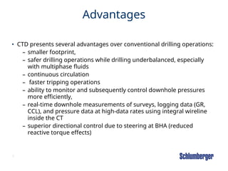
Advantages
• CTD presentsseveral advantages over conventional drilling operations:
– smaller footprint,
– safer drilling operations while drilling underbalanced, especially
with multiphase fluids
– continuous circulation
– faster tripping operations
– ability to monitor and subsequently control downhole pressures
more efficiently,
– real-time downhole measurements of surveys, logging data (GR,
CCL), and pressure data at high-data rates using integral wireline
inside the CT
– superior directional control due to steering at BHA (reduced
reactive torque effects)
9.
9
Limitations
• limited lifeof the CT itself (i.e., cycle fatigue), especially in
larger coiled tubing sizes
• less industry experience compared with conventional drilling,
• additional operating cost due to the need for a downhole
motor.
• reduced horizontal-reach potential, due to sliding friction
10.
10
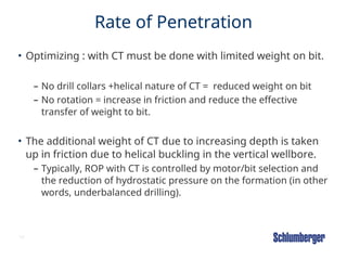
Rate of Penetration
•Optimizing : with CT must be done with limited weight on bit.
– No drill collars +helical nature of CT = reduced weight on bit
– No rotation = increase in friction and reduce the effective
transfer of weight to bit.
• The additional weight of CT due to increasing depth is taken
up in friction due to helical buckling in the vertical wellbore.
– Typically, ROP with CT is controlled by motor/bit selection and
the reduction of hydrostatic pressure on the formation (in other
words, underbalanced drilling).
11.
11
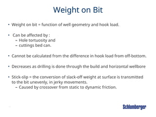
Weight on Bit
•Weight on bit = function of well geometry and hook load.
• Can be affected by :
– Hole tortuosity and
– cuttings bed can.
• Cannot be calculated from the difference in hook load from off-bottom.
• Decreases as drilling is done through the build and horizontal wellbore
• Stick-slip = the conversion of slack-off weight at surface is transmitted
to the bit unevenly, in jerky movements.
– Caused by crossover from static to dynamic friction.
13
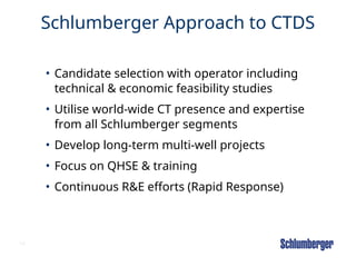
Schlumberger Approach toCTDS
• Candidate selection with operator including
technical & economic feasibility studies
• Utilise world-wide CT presence and expertise
from all Schlumberger segments
• Develop long-term multi-well projects
• Focus on QHSE & training
• Continuous R&E efforts (Rapid Response)
14.
14
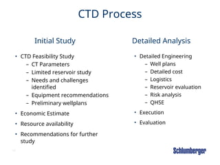
CTD Process
• CTDFeasibility Study
– CT Parameters
– Limited reservoir study
– Needs and challenges
identified
– Equipment recommendations
– Preliminary wellplans
• Economic Estimate
• Resource availability
• Recommendations for further
study
• Detailed Engineering
– Well plans
– Detailed cost
– Logistics
– Reservoir evaluation
– Risk analysis
– QHSE
• Execution
• Evaluation
Initial Study Detailed Analysis
15.
15
Outline
• Training Objectives
•Introduction
• Advantages and Limitations
• Main CTD Applications
• Over vs Under-balance
• Surface Equipment
• Downhole Equipment
• Fluid Requirements
• Technical Overview – Well Example
• Design Considerations
16.
16
Coiled Tubing DrillingApplications
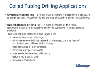
• Overbalanced drilling : drilling fluid pressure > bottomhole pressure
(pore pressure). Reservoir fluids are not allowed to enter the wellbore.
• Underbalanced drilling : BHP < pore pressure of the rock .
Reservoir fluids are allowed to enter the wellbore -> separated at
surface
The underbalanced technique is used to:
– prevent formation damage
– minimize many drilling-related challenges, such as loss of
circulation and differential sticking,
– increase rates of penetration,
– minimize completion costs,
– increase hole-cleaning efficiency,
– reduce mud costs, and
– improve economics
17.
17
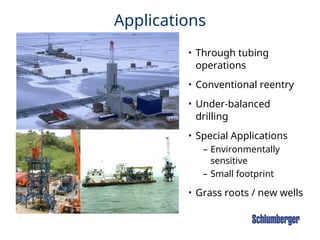
Applications
• Through tubing
operations
•Conventional reentry
• Under-balanced
drilling
• Special Applications
– Environmentally
sensitive
– Small footprint
• Grass roots / new wells
18.
18
Previously-drilled Wells
• Coiledtubing drilling in previously-drilled wells can be performed using
either:
– through-tubing reentry or
– casing reentry.
• Through-tubing Reentry Sidetrack
• The wellbore can be exited either through both the tubing and/or casing
or through the casing below the production tubing.
• This method eliminates the cost of:
– pulling tubing and associated completions equipment and
– running production tubing after drilling.
• Can be performed with either overbalanced or underbalanced techniques.
19.
19
Previously-drilled Wells
• CasingReentry Sidetrack
• Casing reentry is done to deepen wells or for sidetracking and
horizontal drilling.
• Coiled tubing is most effective economically when used to:
– perform short radius drilling,
– when in environmentally sensitive locations, and
– offshore on platforms where a full drilling rig is cost prohibitive.
• Casing reentries can be performed with either overbalanced or
underbalanced techniques.
20.
20
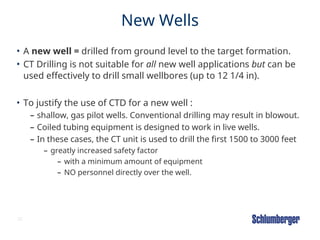
New Wells
• Anew well = drilled from ground level to the target formation.
• CT Drilling is not suitable for all new well applications but can be
used effectively to drill small wellbores (up to 12 1/4 in).
• To justify the use of CTD for a new well :
– shallow, gas pilot wells. Conventional drilling may result in blowout.
– Coiled tubing equipment is designed to work in live wells.
– In these cases, the CT unit is used to drill the first 1500 to 3000 feet
– greatly increased safety factor
– with a minimum amount of equipment
– NO personnel directly over the well.
21.
21
Outline
• Training Objectives
•Introduction
• Advantages and Limitations
• Main CTD Applications
• Over vs. Under-balance
• Surface Equipment
• Downhole Equipment
• Fluid Requirements
• Technical Overview – Well Example
• Design Considerations
22.
22
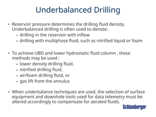
Underbalanced Drilling
• Reservoirpressure determines the drilling fluid density.
Underbalanced drilling is often used to denote:
– drilling in the reservoir with inflow
– drilling with multiphase fluid, such as nitrified liquid or foam
• To achieve UBD and lower hydrostatic fluid column , these
methods may be used :
– lower density drilling fluid,
– nitrified drilling fluid,
– air/foam drilling fluid, or
– gas lift from the annulus
• When underbalance techniques are used, the selection of surface
equipment and downhole tools used for data telemetry must be
altered accordingly to compensate for aerated fluids.
23.
23
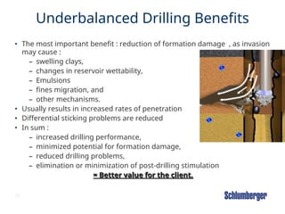
Underbalanced Drilling Benefits
•The most important benefit : reduction of formation damage , as invasion
may cause :
– swelling clays,
– changes in reservoir wettability,
– Emulsions
– fines migration, and
– other mechanisms.
• Usually results in increased rates of penetration
• Differential sticking problems are reduced
• In sum :
– increased drilling performance,
– minimized potential for formation damage,
– reduced drilling problems,
– elimination or minimization of post-drilling stimulation
= Better value for the client.
= Better value for the client.
24.
24
Underbalance Applications
When :
•reservoirs are subject to damage
• reservoirs are depleted or underpressured
• reservoirs are susceptible to drilling problems
• real-time reservoir evaluation can aid in decision-
making
28
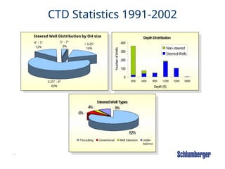
CTD Statistics 1991-2002
SteeredWell Distribution by OH size
4" - 5"
12%
5" - 7"
3%
< 3.25"
16%
3.25" - 4"
69%
Depth Distribution
0
100
200
300
400
3000 6000 9000 12000 15000 18000
Depth(ft)
Num
ber
of
Wells
Non-steered
SteeredWells
SteeredWell Types
4%
82%
8%
6%
Thru-tubing Conventional Well Extension Under-
balance
29.
29
Why CTD?
Financial
• Completioncan stay in place
• Quick tripping with continuous
pipe
• Lower mobilization cost
• Enhanced production from
existing wellheads avoids heavy
infill drilling investment &
infrastructure upgrade
Operational Aspects
• Faster mobilization
• Increased ROP and no
differential sticking (UBD)
• Less personnel
• Fast wireline telemetry and
improved directional control
• Ultra short radius and designer
wells to avoid hazards
Safety and Environment
• Improved well control
• Operational personnel removed
from the well area
• Smaller footprint, noise and height
Reservoir Issues: Increase Overall
Recovery
• Reduce skin damage while drilling
underbalanced
• Reduced pressure surges on formation
30.
30
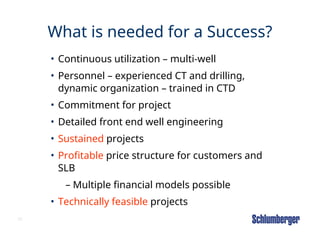
What is neededfor a Success?
• Continuous utilization – multi-well
• Personnel – experienced CT and drilling,
dynamic organization – trained in CTD
• Commitment for project
• Detailed front end well engineering
• Sustained projects
• Profitable price structure for customers and
SLB
– Multiple financial models possible
• Technically feasible projects
31.
31
Outline
• Training Objectives
•Introduction
• Advantages and Limitations
• Main CTD Applications
• Over vs. Under-balance
• Surface Equipment
• Downhole Equipment
• Fluid Requirements
• Technical Overview – Well Example
• Design Considerations
33
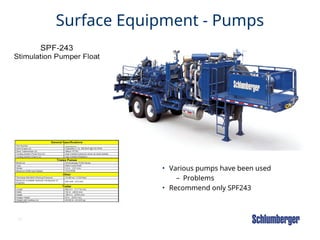
Surface Equipment -Pumps
• Various pumps have been used
– Problems
• Recommend only SPF243
34.
34
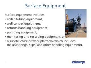
Surface Equipment
Surface equipmentincludes:
• coiled tubing equipment,
• well control equipment,
• returns handling equipment,
• pumping equipment,
• monitoring and recording equipment, and
• a substructure or work platform (which includes
makeup tongs, slips, and other handling equipment).
35.
35
Surface Equipment
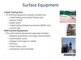
Coiled TubingUnit
• CT Drilling equipment usually includes the:
– coiled tubing and coiled tubing reel,
– injector head,
– power pack,
– coiled tubing blowout preventer (BOP), and
– control cab.
Well Control Equipment
• The well control equipment typically includes:
– blowout preventers (ram-type and annular),
– accumulator units,
– stripper (ram-type or radial),
– kill lines,
– check valves, and
– chokelines and manifolds.
36.
36
Surface Equipment
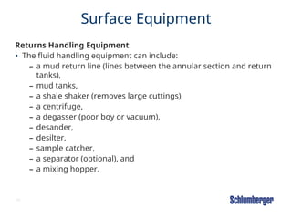
Returns HandlingEquipment
• The fluid handling equipment can include:
– a mud return line (lines between the annular section and return
tanks),
– mud tanks,
– a shale shaker (removes large cuttings),
– a centrifuge,
– a degasser (poor boy or vacuum),
– desander,
– desilter,
– sample catcher,
– a separator (optional), and
– a mixing hopper.
37.
37
Surface Equipment
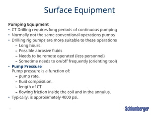
Pumping Equipment
•CT Drilling requires long periods of continuous pumping
• Normally not the same conventional operations pumps
• Drilling rig pumps are more suitable to these operations
– Long hours
– Possible abrasive fluids
– Needs to be remote operated (less personnel)
– Sometime needs to on/off frequently (orienting tool)
• Pump Pressure
Pump pressure is a function of:
– pump rate,
– fluid composition,
– length of CT
– flowing friction inside the coil and in the annulus.
• Typically, is approximately 4000 psi.
38.
38
Surface Equipment
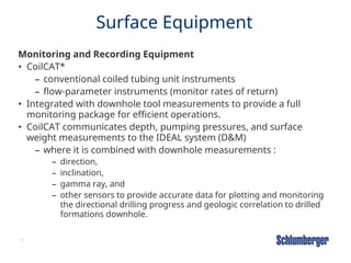
Monitoring andRecording Equipment
• CoilCAT*
– conventional coiled tubing unit instruments
– flow-parameter instruments (monitor rates of return)
• Integrated with downhole tool measurements to provide a full
monitoring package for efficient operations.
• CoilCAT communicates depth, pumping pressures, and surface
weight measurements to the IDEAL system (D&M)
– where it is combined with downhole measurements :
– direction,
– inclination,
– gamma ray, and
– other sensors to provide accurate data for plotting and monitoring
the directional drilling progress and geologic correlation to drilled
formations downhole.
39.
39
CTD Applications Under-balanced
Drilling
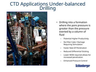
•Drilling into a formation
where the pore pressure is
greater than the pressure
exerted by a column of
fluid
– Potential Higher Productivity
– No Filter Cake / Damage
Requiring Stimulation
– Faster Rate Of Penetration
– Reduced Differential Sticking
– Lower WOB required allows for
increased penetration
– Enhanced Pressure Control
40.
40
X
M
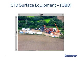
X M
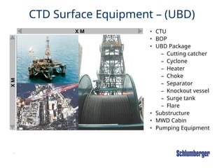
CTD SurfaceEquipment – (UBD)
• CTU
• BOP
• UBD Package
– Cutting catcher
– Cyclone
– Heater
– Choke
– Separator
– Knockout vessel
– Surge tank
– Flare
• Substructure
• MWD Cabin
• Pumping Equipment
41.
41
Outline
• Training Objectives
•Introduction
• Advantages and Limitations
• Main CTD Applications
• Over vs. Under-balance
• Surface Equipment
• Downhole Equipment
• Fluid Requirements
• Technical Overview – Well Example
• Design Considerations
42.
42
Coiled Tubing DownholeEquipment
• Bottomhole assemblies for coiled tubing drilling
applications include:
• motor assembly for nonsteered drilling applications
• directional drilling assembly for directional drilling
• bottomhole assembly for window-milling operations
• bottomhole assemblies, such as those used for running
liners, whipstocks, scrapers, fishing, etc
43.
43
Bottomhole Assembly forNonsteered
Drilling Applications
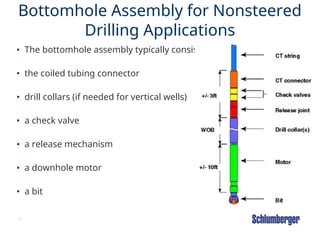
• The bottomhole assembly typically consists of :
• the coiled tubing connector
• drill collars (if needed for vertical wells)
• a check valve
• a release mechanism
• a downhole motor
• a bit
44.
44
Drill Collars
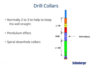
• Normally2 to 3 to help to keep
the well straight .
• Pendulum effect.
• Spiral downhole collars
45.
45
Check Valves
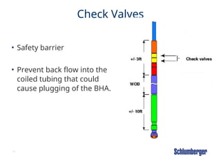
• Safetybarrier
• Prevent back flow into the
coiled tubing that could
cause plugging of the BHA.
46.
46
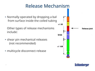
Release Mechanism
• Normallyoperated by dropping a ball
from surface inside the coiled tubing.
Other types of release mechanisms
include:
• shear pin mechanical releases
(not recommended)
• multicycle disconnect release
47.
47
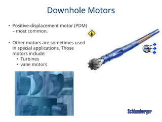
Downhole Motors
• Positive-displacementmotor (PDM)
– most common.
• Other motors are sometimes used
in special applications. Those
motors include:
• Turbines
• vane motors
48.
48
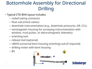
Bottomhole Assembly forDirectional
Drilling
• Typical CTD BHA layout includes:
– coiled tubing connector
– float sub (check valves)
– downhole instrumentation (e.g., downhole pressures, GR, CCL)
– nonmagnetic housing for surveying instrumentation with
wireline, mud pulser, or electromagnetic telemetry
– orienting tool
– release tool (optional)
– UBHO (universal bent housing orienting) sub (if required)
– drilling motor with bent housing
– Bit
49.
49
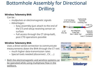
Bottomhole Assembly forDirectional
Drilling
Wireless Telemetry BHA
Can be :
– mudpulses or electromagnetic signals
– Advantages :
– Easy assembly (just attach to the end of
the CT) and setup receiving sensor on
surface
– Full access through the CT (drop-ball) ,
post CTD operations possible
Wireline Telemetry BHA
Uses a direct wired connection to communicate
measurements down the BHA through the CT reel.
– much higher data-transmission rates
– Special tools needed (disconnect , CV , …)
• Both the electromagnetic and wireline systems can
be operated while using multiphase flow in the
wellbore.
50.
50
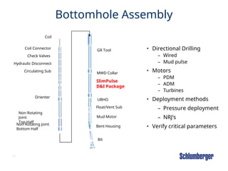
Bottomhole Assembly
• DirectionalDrilling
– Wired
– Mud pulse
• Motors
– PDM
– ADM
– Turbines
• Deployment methods
– Pressure deployment
– NRJ’s
• Verify critical parameters
Coil
Coil Connector
Check Valves
Hydraulic Disconnect
Circulating Sub
Non Rotating
Joint
Top Half
Non Rotating Joint
Bottom Half
MWD Collar
Orienter
UBHO
Mud Motor
Bit
GR Tool
SlimPulse
D&I Package
Float/Vent Sub
Bent Housing
54
Wired Telemetry
• Providers
–Weatherford
– BJS
– Baker Hughes Inteq
•Fully integrated and modular CTD system
•BHA setup can be changed to customer
requirement
•High speed communication via single conductor
wireline
•Precise wellbore placement due to bi-directional
steering with closed loop automatic
steering control
•Multiple standard sensors: directional, gamma,
temperature, casing collar locator
•Optional sensors: WOB, annular and string
pressure in the drilling performance sub
53.
55
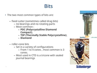
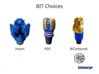
Bits
• The twomost common types of bits are:
– fixed cutter (sometimes called drag bits)
– no bearings and no rotating parts
– Most common :
– PDC (Polycrystalline Diamond
Compact),
– TSP (Thermally Stable Polycrystalline),
– Diamond
– roller-cone bits
– Set in a variety of configurations
– From 1 to 4 cones , most common is 3
cones.
– Most used in CTD is a tricone with sealed
journal bearings
60
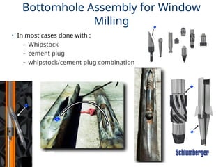
Bottomhole Assembly forWindow
Milling
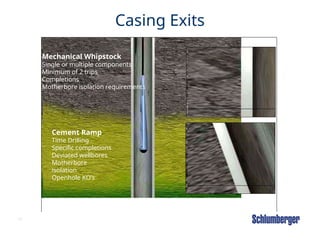
• In most cases done with :
– Whipstock
– cement plug
– whipstock/cement plug combination
59.
61
Special Purpose Bottomhole
Assemblies
Thereare a number of special purpose bottomhole tools used
during coiled tubing drilling operations. These include :
– drilling and fishing jars
– accelerators underreamers
– float subs
– overshots or spears
60.
62
Outline
• Training Objectives
•Introduction
• Advantages and Limitations
• Main CTD Applications
• Over vs. Under-balance
• Surface Equipment
• Downhole Equipment
• Fluid Requirements
• Technical Overview – Well Example
• Design Considerations
61.
63
Coiled Tubing DrillingFluids
Requirements
• Drilling fluids issues for CT Drilling are not much different
from conventional drilling with a few exceptions:
• Cuttings bed buildup = more problematic with CT (no
rotation)
• Continuous circulation = no settling during connections .
• Lower circulating pressure (rates) on the CT when
compared to DP
62.
64
Fluid Hydraulics
• Twomajor factors governing flow rates on CTD :
• The downhole motor
– By-pass = more flow (on single-phase)
• The maximum allowable surface pressure
– CT Yield Strength
– Pressure drop across Ct and any component of the BHA must
be taken into consideration on the design phase
63.
65
Outline
• Training Objectives
•Introduction
• Advantages and Limitations
• Main CTD Applications
• Over vs. Under-balance
• Surface Equipment
• Downhole Equipment
• Fluid Requirements
• Technical Overview – Well Example
• Design Considerations
64.
66
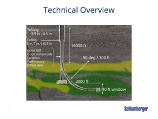
Technical Overview
16000 ft
3000ft
50 deg / 100 ft
Tubing
3.5 in , 4.5 in
Casing
5 in, 7 in, 9.625 in
Good MIT
Good cement job
Isolation
Well history
Offset data
10 ft window
65.
67
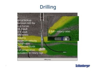
Drilling
WOB
Helical lockup
Minimum 600lbs
Hydraulics
Minimum velocity
Pump rates
Optimized fluids
Rate of penetration
Equivalent to rotary rigs
Tubing Forces
100 K pull
40 K snub
80% stress
5 fph – rotary rates
69
Outline
• Training Objectives
•Introduction
• Advantages and Limitations
• Main CTD Applications
• Over vs. Under-balance
• Surface Equipment
• Downhole Equipment
• Fluid Requirements
• Technical Overview – Well Example
• Design Considerations
68.
W E LL S E R V I C E S
W E L L S E R V I C E S
Module CT05
CTD CoilCADE
69.
71
CTD CoilCADE
• 1st
TRUTH: NO REAL CTD GUIDELINES FOR COILCADE
• 2ND
TRUTH : BEST MODELING IS FROM EXPERIENCE
• 3RD
TRUTH : RESEARCH , RESEARCH , RESEARCH…
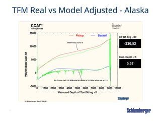
75
TFM Real vsModel Adjusted - Alaska
-236.52
CT Wt Avg - lbf
0.97
Corr. Depth - ft
0 1000 2000 3000 4000 5000 6000 7000 8000 9000 10000
Measured Depth of Tool String - ft
-5000
0
5000
10000
15000
W
eig
h
t
In
d
icato
r
L
o
ad
-
lb
f
Pickup Slackoff
RIH - Friction Coeff 0.25, WOB while RIH 1500lbs, at TD 2750lbs before lock up
POOH Friction Coef 0.10
CCAT*
(c) Schlumberger Dowell 1994-99
Tubing Forces
bp
MPH-08a Plan 1
Set Whipstock
14 March 01
74.
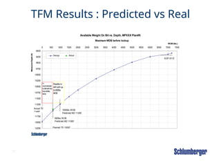
77
TFM Results :Predicted vs Real
Available Weight On Bit vs. Depth, MPXXX Plan#X
9000
9250
9500
9750
10000
10250
10500
10750
11000
11250
11500
11750
12000
12250
0 500 1000 1500 2000 2500 3000 3500 4000 4500 5000 5500 6000 6500 7000 7500
WOB (lbs.)
Measured
Depth
(ft)
Design Actual
Maximum WOB before lockup
600lbs WOB
Predicted MD 11500'
KOP 9110'
Planned TD 13000'
1000lbs WOB
Predicted MD 11250'
Possibleto
drill withup
to600lbs
WO
B
No
recom
m
ended
todrillwithless
than600lbs
WO
B
Actual TD
11448'
75.
78
WBS FOR DRILLING
•Will calculate :
– Cuttings to surface
– Hydraulics dynamically
– BHP
– Pressures
76.
79
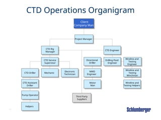
CTD Operations Organigram
Client
CompanyMan
Project Manager
CTD Engineer
CTD Rig
Manager
Drilling Fluid
Engineer
Directional
Driller
Wireline and
Testing
Engineer
CTD Service
Supervisor
CTD Driller
Pump Operator
Helpers
Mechanic
Electronic
Technician
MWD
Engineer
Motor
Man
Third Party
Suppliers
Wireline and
Testing
Winchman
Wireline and
Testing Helpers
CTD Assistant
Driller
77.
80
Summary
• CTD isa niche application
• Primary markets
– Thru-tubing reentries
– UBD
• Full evaluation mandatory by experienced personnel
• Multiple-well campaigns are necessary
• QUESTIONS ????
78.
81
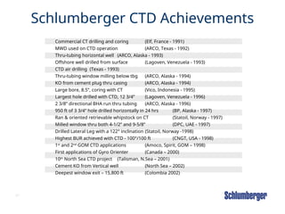
Schlumberger CTD Achievements
CommercialCT drilling and coring (Elf, France - 1991)
MWD used on CTD operation (ARCO, Texas - 1992)
Thru-tubing horizontal well (ARCO, Alaska - 1993)
Offshore well drilled from surface (Lagoven, Venezuela - 1993)
CTD air drilling (Texas - 1993)
Thru-tubing window milling below tbg (ARCO, Alaska - 1994)
KO from cement plug thru casing (ARCO, Alaska - 1994)
Large bore, 8.5”, coring with CT (Vico, Indonesia - 1995)
Largest hole drilled with CTD, 12 3/4” (Lagoven, Venezuela - 1996)
2 3/8” directional BHA run thru tubing (ARCO, Alaska - 1996)
950 ft of 3 3/4” hole drilled horizontally in 24 hrs (BP, Alaska - 1997)
Ran & oriented retrievable whipstock on CT (Statoil, Norway - 1997)
Milled window thru both 4-1/2” and 9-5/8” (DPC, UAE - 1997)
Drilled Lateral Leg with a 122° inclination (Statoil, Norway -1998)
Highest BUR achieved with CTD - 100°/100 ft (CNGT, USA - 1998)
1st
and 2nd
GOM CTD applications (Amoco, Spirit, GOM – 1998)
First applications of Gyro Orienter (Canada – 2000)
10th
North Sea CTD project (Talisman, N.Sea – 2001)
Cement KO from Vertical well (North Sea – 2002)
Deepest window exit – 15,800 ft (Colombia 2002)
Editor's Notes
#5 Reference: IT Module CT Drilling
There are some important differences between coiled tubing drilling techniques and conventional (rotary) drilling techniques. The main difference is that coiled tubing drilling must use downhole motors, orienting tools and other special equipment to circumvent the inability to rotate the pipe. While the advantages of not having to make connections and being able to continuously circulate while tripping into or out of the wellbore are beneficial, these additional benefits are offset somewhat by the additional equipment requirement.
With normal drilling operations with drill pipe, circulation of the well needs to be stopped to be able to make the connections. Many problems like lost circulation and stuck pipe can occur during this period.
Another significant difference is that coiled tubing drilling can use not only the coiled tubing itself to provide weight on the bit, but can use the injector to apply snubbing forces to the coiled tubing when drilling horizontally.
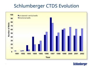
The use of coiled tubing for directional drilling has increased dramatically since 1991.
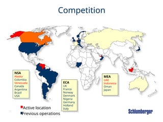
Schlumberger launched its CTD effort in 1991, and from 1991 to 1995, Schlumberger performed more than twice as many CTD operations as all of its competitors combined.
In the last few years, competitor activity in Canada and other focused areas has increased drastically.
#8 Reference: IT Module CT Drilling
This minimizes damage to the reservoir by eliminating the need to drill the well as is normally required with a conventional drilling rig. Underbalanced drilling also permits the well to produce while it is being drilled.
Although underbalanced drilling can also be performed by certain rigs with jointed-pipe equipment, tripping and completion activities require that the well be killed - significantly impairing any results from underbalanced drilling. Coiled tubing drilling allows the well to be maintained in an underbalanced state throughout the drilling and completion operations, virtually eliminating any wellbore damage and possibly reducing the need for well stimulation afterwards.
Another major advantage of coiled tubing or drilling related activities is the ability to install a wireline inside the coiled tubing itself. The insertion and removal of any electric steering tools, packers, logging tools, or the equipment into the well is conducted in an effortless, efficient manner by simply spooling the coiled tubing. This ability to perform trips quickly is a major advantage when performing operations on deep wells.
In certain cases, coiled tubing operations may require less personnel than conventional drilling rigs; however, due to the performance of different activities this reduction may not be significant. For example, a well drilled underbalanced may not be cased, and therefore, the casing crews, cementing crews, perforating crews, etc., such as may be needed for normal wells, are not required.
The footprint of a coiled tubing drilling unit is usually significantly smaller than a conventional drilling rig. This smaller footprint can be attributed to the use of a reel versus pipe racks with jointed pipe, and the use of an injector versus a derrick and drawworks. However, the main reason for the difference is the fact that most drilling rigs are built to handle larger hole sizes and larger downhole equipment. Coiled tubing drilling is mainly a technique for drilling in the target reservoir formation, although some unique applications utilize CTD to drill large (up to 12 ¾ in) surface and intermediate hole sizes.
Research and development of coiled tubing for drilling has proven it to be both technically feasible and economical in the right applications. This makes it a viable alternative to conventional drilling, especially offshore and in environmentally-sensitive areas.
Coiled tubing units are used to drill in environmentally-sensitive areas because of the efficiency in using a closed loop system due to no connections. The coiled tubing drilling package also has less exhaust emissions and greatly-reduced noise levels. Due to the small diameter holes being drilled, there are reduced quantities of drilling fluids to be mixed, and less drill cuttings to dispose.
The major attraction to coiled tubing drilling in the long-term is the fact that the technology is particularly advantageous when used for underbalanced drilling, short radius, and multilateral applications.
#10 Reference: IT Module CT Drilling
Optimizing rate of penetration with coiled tubing must be done with limited weight on bit. Due to the absence of drill collars and the helical nature of coiled tubing, weight on bit is reduced. The inability to rotate the coiled tubing also serves to increase friction and reduce the effective transfer of weight to bit. The weight transferred to the bit does come from the weight of the coiled tubing; however, available weight on bit does not increase with increased depth.
The additional weight of coiled tubing due to increasing depth is taken up in friction due to helical buckling in the vertical wellbore. Typically, rate of penetration with coiled tubing is controlled by motor/bit selection and the reduction of hydrostatic pressure on the formation (in other words, underbalanced drilling).
#11 Reference: IT Module CT Drilling
Weight on Bit
Weight on bit is a function of well geometry and hook load. Hole tortuosity and the existence of a cuttings bed can also detract from the ability to transfer weight to bit. Weight on bit cannot be calculated from the difference in hook load from off-bottom. Some of the hook load weight is lost in friction due to helical buckling.
The percentage of hook load weight transferred to the bit decreases as drilling is done through the build and horizontal wellbore. The phenomenon of stick-slip also causes the conversion of slack-off weight at surface to be transmitted to the bit unevenly, in jerky movements. This is due to the crossover from static to dynamic friction. Other factors that affect weight on bit include casing size and hole size.
#13 In order for CTD to succeed and prove profitable and a value solution for the client the projects that will be developed must meet certain criteria. These criteria are outlined below:
The candidate wells must be chosen with technical and economic feasibility in mind. In the past wells have been chosen without sufficient engineering and planning and have not proven a viable solution to either the client or Schlumberger. Though the use of our CTD project managers working closely with the client the appropriate candidates and projects will be developed.
The worldwide expertise that Schlumberger has developed over the last 12 years will be brought to each and every project that is undertaken. Schlumberger has drilled wells in just about every climate available on the planet. From the arctic to the jungle, on-land and offshore, on lake and in the desert Schlumberger has paved the way forward for coiled tubing drilling applications.
The focus on long term, multi-well contracts brings to bear the learning curve associated with new drilling opportunities. Time and again the plot of efficiency versus the number of wells can be charted to prove that initially CTD may not prove much of a cost savings over conventional rotary rigs. With continued operations (5+) wells the efficiency for the entire operation increases. As illustrated in slides later, a recent program in Indonesia decreased RU/RD time by over 70% and NPT dropped from 7% to 0%.
Schlumberger has a steadfast commitment to QHSE. Schlumberger has a track record as a leader in safety, and environmental awareness. Two training centers, one in the US and the other in the UK, provide training for our field and technical staff . One of these centers located in the UK is a combined facility between Drilling and Measurements and Well Services.
New technology is the cornerstone of Schlumberger’s image. The SlimPulse directional drilling system is best in class with over 2 million operating hours logged with the technology. New and evolving systems are constantly being developed my our product and engineering centers.
#16 Reference: IT Module CT Drilling
prevent formation damage= caused by entry of damaging drilling fluids to the formation
increase hole-cleaning efficiency =due to reservoir inflow
improve economics =by providing early reservoir production.
Both techniques can be used on new and previously-drilled wells. When drilling in a previously-drilled well, casing reentry may be used (with tubing removed), or reentry can be done through the existing tubing, if the tubing is large enough to accommodate current equipment (3-1/2 inch tbg and larger).
Coiled tubing is especially attractive for slimhole applications, due to susceptibility to joint failure in conventional slimhole pipe.
Overbalanced drilling is drilling with a fluid that exerts sufficient bottomhole pressure to exceed that of the pore pressure in the rock surrounding the wellbore. Reservoir fluids are not allowed to enter the wellbore.
Underbalanced drilling is drilling with a bottomhole pressure below that of the pore pressure of the rock surrounding the wellbore. Reservoir fluids are allowed to enter the wellbore and are separated at the surface from the drilling fluid. The underbalanced technique is used to:
prevent formation damage
minimize many drilling-related challenges, such as loss of circulation and differential sticking,
increase rates of penetration,
minimize completion costs,
increase hole-cleaning efficiency,
reduce mud costs, and
improve economics
#17 Coiled tubing drilling Is a niche application. CTD is not a direct alternative for rotary drilling. In order for a CTD campaign to proceed one or more of the following drivers must be valid.
Through tubing or conventional operations
Under-balanced drilling
Drilling in limited access areas or under environmental constraints
Grass root / new wells
#18 Reference: IT Module CT Drilling
Through-tubing reentry means that the coiled tubing reenters the wellbore through existing production tubing. This method requires the entire bottomhole assembly to be able to pass through the tubing. This method is used to deepen wells and for directional sidetrack to increase flow area or access new reservoir targets. The wellbore can be exited either through both the tubing and/or casing or through the casing below the production tubing.
This method eliminates the cost of:
pulling tubing and associated completions equipment and
running production tubing after drilling.
#19 Reference: IT Module CT Drilling
Casing Reentry Sidetrack
With casing reentry, the coiled tubing reenters the wellbore through the casing - any production tubing or packers are removed prior to initiating the wellbore exit. Casing reentry is done to deepen wells or for sidetracking and horizontal drilling.
#20 Reference: IT Module CT Drilling
A new well is a well that is drilled from ground level to the target formation. Coiled tubing drilling is not suitable for all new well applications but can be used effectively to drill small wellbores (up to 12 1/4 in).
Many times coiled tubing drilling techniques are used to perform drilling operations that cannot be done with conventional rotary drilling. One such application is the use of CTD to drill shallow, gas pilot wells. Conventional drilling operations are performed under balanced conditions using the weight of the mud as the primary pressure barrier. Drilling shallow overpressured gas pockets may result in blowout. Coiled tubing equipment is designed to work in live wells. In these cases, the coiled tubing unit is used to drill the first 1500 to 3000 feet of a known shallow gas area. The reason for this is the greatly increased safety factor using the CTU, with a minimum amount of equipment and NO personnel directly over the well. After casing has been set over the shallow gas zone, a conventional rig can be brought in to finish drilling the well.
#22 Reference: IT Module CT Drilling
When underbalanced drilling is required, reservoir pressure determines the drilling fluid density. Underbalanced drilling is often used to denote drilling in the reservoir with inflow from the reservoir and also to define drilling with multiphase fluid, such as nitrified liquid or foam, even though bottomhole pressure may be above pore pressure. Depending upon certain conditions,
When underbalance techniques are used, the selection of surface equipment and downhole tools used for data telemetry must be altered accordingly to compensate for aerated fluids.
#23 Reference: IT Module CT Drilling
When underbalanced drilling is required, reservoir pressure determines the drilling fluid density. Underbalanced drilling is often used to denote drilling in the reservoir with inflow from the reservoir and also to define drilling with multiphase fluid, such as nitrified liquid or foam, even though bottomhole pressure may be above pore pressure. Depending upon certain conditions,
lower density drilling fluid,
nitrified drilling fluid,
air/foam drilling fluid, or
gas lift from the annulus
may be used to reduce the hydrostatic fluid column inside the well and achieve underbalance.
When underbalance techniques are used, the selection of surface equipment and downhole tools used for data telemetry must be altered accordingly to compensate for aerated fluids.
#24 Reference: IT Module CT Drilling
reservoirs are subject to damage (such as a formation with clay that would be sensitive to water),
reservoirs are depleted or underpressured (so that the reservoir can be drilled through without extreme losses of drilling fluids)
reservoirs are susceptible to drilling problems such as loss of circulation and differential sticking,
a reservoir is relatively competent and drilling performance can benefit from increased rates of penetration, and
real-time reservoir evaluation can aid in decision-making (for example, prematurely abandoning a wellbore due to water production to save money on evaluation and completion).
#32 This surface layout will vary depending on the requirements of the specific job and the equipment available. At the very minimum the required equipment will be a crane truck, CTU, pump system, fluids handling equipment and MWD cabin. The location size can be as small as 8000 sq ft.
The standard equipment for the coiled tubing unit will be an injector capable of pulling 80K lbs, and a open loop high pressure powerpack. The reel should be capable of handling the amount and OD of the coiled tubing needed to TD with 1000 ft additional CT. The types of pumps used are fracturing or cementing pumps with remote control capability and flow rates from 0.5 bpm to 8 bpm. The fluids system can vary significantly and it is avdised to coordinate with a local mud conditioning company to determine the requirements for each specific job. At a minimum tanks are needed with a sufficient volume as per Standard 22a, a degasser, a centrifuge and a mixing hopper.
#34 Reference: IT Module CT Drilling
The well control equipment typically includes:
blowout preventers (ram-type and annular),
accumulator units,
stripper (ram-type or radial),
kill lines,
check valves, and
chokelines and manifolds.
5.3
Returns Handling Equipment
The fluid handling equipment can include:
• a mud return line (lines between the annular section and return tanks),
• mud tanks,
• a shale shaker (removes large cuttings),
• a centrifuge,
• a degasser (poor boy or vacuum),
• desander,
•
desilter,
•
sample catcher,
•
a separator (optional), and
•
a mixing hopper.
Normally, there are three functions that are needed for mud tanks:
•
a settling tank for mud from the well and the shaker,
•
an active tank for mud going into the well, and
•
a reserve tank for new or heavier mud.
Separators are used if gas or oil is produced while drilling and are positioned so that all flow returning from the well must first pass through the separator.
5.4
Pumping Equipment
Coiled tubing drilling requires long periods of continuous pumping of drilling fluids and doesn't normally employ the same high- and low-pressure pumping equipment used in other Schlumberger applications.
Plunger pumps capable of pumping drilling fluid for long, uninterrupted periods of time are used, similar to those used in conventional drilling operations. In order to reduce personnel required, mud pumps are positioned with controls in the coiled tubing cabin so that the operator can start and stop the pumps as may be required to operate orienting tools and other downhole equipment.
5.4.1
Pump Pressure
Pump pressure is a function of:
•
pump rate,
•
fluid composition,
•
length of coil, and
•
flowing friction inside the coil and in the annulus.
Typically, pump pressure is reduced through the use of multiphase fluid. A maximum desired pumping pressure for pipe that does not remain on the reel is approximately 4000 psi.
5.5
Monitoring and Recording Equipment
In addition to the conventional coiled tubing unit instruments, coiled tubing drilling requires drilling-parameter instruments for information about activities downhole and flow-parameter instruments to monitor rates of return. The CoilCAT* system is normally used for monitoring and recording drilling parameters from the coiled tubing unit, and is integrated with downhole tool measurements to provide a full monitoring package for efficient operations. The CoilCAT system communicates depth, pumping pressures, and surface weight measurements to the IDEAL system (Anadrill) where it is combined with downhole measurements of direction, inclination, gamma ray, and other sensors to provide accurate data for plotting and monitoring the directional drilling progress and geologic correlation to drilled formations downhole.
#36 Reference: IT Module CT Drilling
Normally, there are three functions that are needed for mud tanks:
a settling tank for mud from the well and the shaker,
an active tank for mud going into the well, and
a reserve tank for new or heavier mud.
Separators are used if gas or oil is produced while drilling and are positioned so that all flow returning from the well must first pass through the separator.
#37 Reference: IT Module CT Drilling
Pumping Equipment
Coiled tubing drilling requires long periods of continuous pumping of drilling fluids and doesn't normally employ the same high- and low-pressure pumping equipment used in other Schlumberger applications.
Plunger pumps capable of pumping drilling fluid for long, uninterrupted periods of time are used, similar to those used in conventional drilling operations. In order to reduce personnel required, mud pumps are positioned with controls in the coiled tubing cabin so that the operator can start and stop the pumps as may be required to operate orienting tools and other downhole equipment.
Pump Pressure
Pump pressure is a function of:
pump rate,
fluid composition,
length of CT
flowing friction inside the coil and in the annulus.
Typically, pump pressure is reduced through the use of multiphase fluid. A maximum desired pumping pressure for pipe that does not remain on the reel is approximately 4000 psi.
#38 Reference: IT Module CT Drilling
Monitoring and Recording Equipment
In addition to the conventional coiled tubing unit instruments, coiled tubing drilling requires drilling-parameter instruments for information about activities downhole and flow-parameter instruments to monitor rates of return. The CoilCAT* system is normally used for monitoring and recording drilling parameters from the coiled tubing unit, and is integrated with downhole tool measurements to provide a full monitoring package for efficient operations. The CoilCAT system communicates depth, pumping pressures, and surface weight measurements to the IDEAL system (Anadrill) where it is combined with downhole measurements of direction, inclination, gamma ray, and other sensors to provide accurate data for plotting and monitoring the directional drilling progress and geologic correlation to drilled formations downhole.
#44 Reference: IT Module CT Drilling
For vertical wellbores, a small amount of drill collars (typically 2 or 3) can be used to assist in maintaining a straight wellbore. The size and exact length varies with the hole size being drilled. The resulting "pendulem" effect is most effective when drilling softer formations or when minimal weight on bit can be used to drill effectively. No stabilizers are normally run during coiled tubing drilling. Spiral downhole collars are preferred due to their reduced sticking tendencies.
#45 Reference: IT Module CT Drilling
Check valves are run to prevent back flow into the coiled tubing that could cause plugging of the BHA. They also provide an internal safety barrier for the coiled tubing in the event of a well control event
#46 Reference: IT Module CT Drilling
The hydraulic release mechanism (or joint) is operated by dropping a ball from surface inside the coiled tubing. When the ball reaches the fishing tail, the pressure rises because the ball seats against a piston, which stops the flow. This pressure then shears a set of brass pins holding the piston in place, the piston shifts, and the joint is released.
Other types of release mechanisms include:
shear pin mechanical releases (generally not used, as the torque and vibrations during the drilling operation tend to weaken the pins)
multicycle disconnect release (movement of the CT string above the stuck BHA element is used to operate the release mechanism)
#47 Reference: IT Module CT Drilling
The most commonly used downhole motor is a positive-displacement motor (PDM). The PDM is driven by the drilling fluid that passes through the motor. The fluid passes through a rotor/stator section (similar to a spiral) and causes rotation of the inner rotor.
Other motors are sometimes used in special applications where extreme temperature or other parameters are unfit for a PDM. Those motors include:
turbines
vane motors
Here is a positive-displacement motor. These motors come in different configurations of rotor/stator ratios and number of stages which affect their speed and torque capabilities. Typically, higher-torque motors are preferred for coiled tubing drilling. In positive-displacement motors, there are two types of bearing sections:
Turbines produce high speed; however, they can be used with gear reductions to reduce speed and increase torque.
Turbines employ multiple sections of rotating blades that are activated by fluid passing through the motor. Due to the multiple sections, turbine motors typically operate at pressures three to four times higher than PDM motors.
Vane motors are typically made of metallic and ceramic/composite materials, and require very clean fluid to operate. They use vanes, similar to the design concept in a rotary engine that turn via high-pressure and low-pressure areas due to injection/exhaust ports
Some are fluid lubricated by leaking small amounts of the drilling fluid through them.
Some contain sealed bearings, which do not require drilling fluid for lubrication.
#48 This illustration shows a typical bottomhole assembly for directional drilling. From the bottom up, a typical directional-drilling bottomhole assembly could include the following:
coiled tubing connector
float sub (check valves)
downhole instrumentation (e.g., downhole pressures, GR, CCL)
nonmagnetic housing for surveying instrumentation with wireline, mud pulser, or electromagnetic telemetry
orienting tool
release tool (optional)
UBHO (universal bent housing orienting) sub (if required)
drilling motor with bent housing
Bit
#49 General types of Bottomhole Assemblies
Two general types of bottomhole assemblies are used to perform directional drilling operations:
wireless telemetry and wireline telemetry
4.2.1.1
Wireless Telemetry BHA
Wireless telemetry can be performed using either mudpulses or electromagnetic signals to communicate measurements from the BHA to the operator at the surface. Both systems are convenient, in that the directional drilling assembly can simply be attached to the end of the coiled tubing and sensors placed at the surface to receive the data at the surface. Full access through the coiled tubing is possible, so many of the drop-ball activated tools used with non-steered BHA's are useable.
4.2.1.2
Wireline Telemetry BHA
Wireline telemetry, as the name implies, uses a direct, wired connection to communicate measurements down the BHA to operators at the surface. These "e-line" systems use a hardwired connection from the downhole tool, through the coiled tubing reel, and through a collector ring on the coiled tubing reel, which allows much higher data-transmission rates than either of the wireless telemetry systems. Because a wireline now passes through the BHA and coiled tubing, special tools are needed to disconnect and perform other functions downhole.
Both the electromagnetic and wireline systems can be operated while using multiphase flow in the wellbore.
#51 This slide shows performance specifications for the SlimPulse MWD system and a tool diagram. While it is important to emphasize several points about the SlimPulse MWD tool (servo pulser anti-jamming feature, battery power conservation technology, hot hole capability to 175 degC, configuration adaptability for battery on top or bottom) the Curvature specification deserves some explanation. Essentially the collars that are used to house the SlimPulse MWD tool will dictate the build rate capability … collars are the limiting factor to consider. But before we tell all our clients that a SlimPulse CTD BHA can be used for a 100 deg / 100 foot curve (and this is true when considering the SlimPulse MWD by itself), we need to consider that two of the other essential elements of the CTD BHA cannot drill at these build rates.
Specifically the SLB 3-1/8” Drilling Connector has shown good performance up to 40 deg / 100 feet but beyond this we have noticed some stress cracks in the internal 2.06” stub acme pins. Efforts are currently underway to change to 2-3/8” API connections within the 3-1/8” Drilling Connector which should safely allow build rate capability to 50 deg/ 100 feet.
The other BHA component that should be considered is the mechanical orienter currently provided by Sperry Sun and Weatherford in Prudhoe Bay. Each of these orienters have shown operational difficulties at higher build rates and applications above 40 deg / 100 feet should not be attempted without considerable scrutiny. Fortunately the TORC system, meant to replace these mechancal orienters is designed for build rates exceeding 50 deg / 100 feet.
#52 These are the summary bullet points for the SlimPulse MWD system. For further information please refer to the following URL on the SLB Hub:
http://www.hub.slb.com/index.cfm?id=id12301
#55 Reference: IT Module CT Drilling
Fixed cutter bits have no bearings and no rotating parts. They use a shearing action similar to machining to cut the rock and have cutting edges that cut as they are rotated by the motor above. The most common drag bits are
PDC (Polycrystalline Diamond Compact), which are used for soft-to-medium formations
TSP (Thermally Stable Polycrystalline), which are used for medium-to-hard formations
Diamond, which are used for hard formations
PDC refers to the cutter that is mounted on posts. TSP uses synthetic diamonds set in a matrix. They are typically less aggressive than PDCs but can withstand harder, more abrasive formations. The gauge protection on a PDC bit is typically made from thermally-stable diamond or tungsten carbide inserts.
Fixed cutter bits can be rebuilt (or redressed) and used again.
4.1.6.2
Roller-cone bits come in a variety of configurations. They can be found with as few as one cone to as many as four on larger bits; however, the most common configuration is the three-cone, or tri-cone, bit. The teeth are either milled steel or tungsten carbide inserts with various nozzle configurations to assist in debris removal. Many of the new designs can also be found with diamond-coated cutters to aid in wear resistance.
Bearings range from nonsealed roller bearings to sealed journal bearings. Typically, the sealed journal bearings are recommended for most coiled tubing drilling applications, with the exception of some vertical deepenings and scale-cleanout operations where short drilling times are anticipated. Gauge protection is important when using these bits in horizontal wellbores.
#60 Reference: IT Module CT Drilling
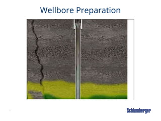
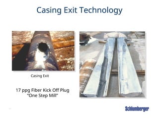
Window milling refers to cutting casing to begin directional drilling. As discussed above, this can be done conventionally or through tubing.
Typically, mills are used to mill steel (either windows or junk or scale, etc.), but are generally poor for drilling most formations. Mills can also be used to mill cement, such as for cement plug kickoffs.
Here is a typical whipstock. The whipstock is a hard metal device set in the casing that guides the mill into the side of the casing. The mill produces a cut or window in the casing.
Here is a cement plug kickoff.
In this case, a very hard tough cement plug is set. The plug usually contains fibers to maintain its integrity when drilled.
A pilot hole is then drilled, and the string is pulled out of hole.
A bent housing motor and directional drilling assembly is then used to drill through the casing by using a "time drilling" technique. This technique, along with specially designed wells to assist in cutting the casing, has proven to be a reliable alternative when whipstocks cannot be used.
Drilling can then continue through the window - care must be used when passing the bit and BHA through the window to prevent damaging the remaining cement around the exit window.
This is also a combination cement plug and whipstock configuration.
This illustration shows both the side-cutting mill, or "speed mill", used to cut the casing and the "watermellon mill" used to expand and dress the window.
This illustration shows a typical window-milling bottomhole assembly with whipstock, watermelon mill, and speed mill, compared with a conventional bottomhole assembly. After milling the window through the casing of the well, the directional drilling assembly is then used to continue drilling in the formation to the reservoir target.
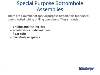
#61 Special Purpose Bottomhole Assemblies
There are a number of special purpose bottomhole tools used during coiled tubing drilling operations. These include
drilling and fishing jars (which give extra pull by means of a "hammer" - type action when stuck or fishing)
accelerators (which "accelerate" or increase the force of the jarring effect in either direction while absorbing the shock to the BHA or coiled tubing)
underreamers (which have expandable cutting arms to create a hole with a wider diameter than the inside diameter of the tubing or casing string that must be passed through)
float subs (which are check valves in the BHA)
overshots or spears (which are used for fishing)
#63 Reference: IT Module CT Drilling
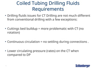
Coiled Tubing Drilling Fluids Requirements
Drilling fluids issues for coiled tubing drilling are not much different from conventional drilling with a few exceptions:
• Cuttings bed buildup can be more problematic with coiled tubing because of the lack of mechanical agitation normally provided by drill pipe rotation.
• Coiled tubing has the ability to maintain continuous circulation and thus avoid the settling of cuttings that can be associated with discontinuation of circulation.
• Circulating rates through the coiled tubing and associated BHA are usually lower than can be obtained with drill pipe, and this reduction in rates similarly affects the ability to lift and remove cuttings in some sections of the wellbore.
These differences can be quite important when considering fluid design, particularly in horizontal wellbores. Drilling fluids with high gel strengths and carrying capacity are excellent for lifting cuttings in vertical wellbores; however, it is more difficult to achieve turbulent flow conditions, which are required to minimize cuttings-bed buildup in the horizontal wellbore.
Drilling fluids that can achieve turbulent flow conditions easier are preferable for cleaning the horizontal wellbore; however, these drilling fluids are susceptible to cuttings dropout in the build section. The ability to maintain continuous circulation aids in minimizing this problem; however, this is still an area that is being studied and warrants improvement.
In through-tubing coiled tubing drilling applications it is necessary to keep both the tubing and any casing below clean of cuttings buildup. This can be particularly challenging to accomplish with a single drilling fluid.
#64 Reference: IT Module CT Drilling
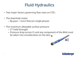
Fluid Hydraulics
When drilling with coiled tubing, the flow rates are especially important, as they relate to the hole-cleaning requirements of the wellbore and the bottomhole assembly flow capacity.
Some motors are equipped with a bypass (a port milled through the middle of the rotor) to increase fluid flow. These can work well when single-phase fluids are employed; however, they add significant complication to the use of multiphase fluids and are not recommended to be used in these applications. Motor specifications for fluid flow must be carefully considered during the job-design phase.
The maximum allowable surface pressure of the coiled tubing and the pressure drop through the motor and other bottom hole assembly elements must be taken into consideration during the design phase to ensure sufficient hole-cleaning parameters are available with a given coiled tubing and well geometry.
#70
Introduction to module
The purpose of this module is to get attendees familiar with the general CTD Design and Planning Best Practices .
Reference: CT operators Manual (See Monograph)
Homework: YES - Homework is to be handed out at the end of the class on accumulator sizing
NOTE: BOP & Stripper Assembly & Disassembly is required to be done to complete this module on OTS1 & STEP1
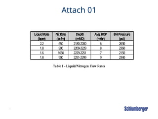
#72 The table shows the comparison of varying the BHP by changing liquid and N2 rates , and how that affects the ROP . Not always the lowest BHP will translate in faster ROPs.