Download to read offline


![18
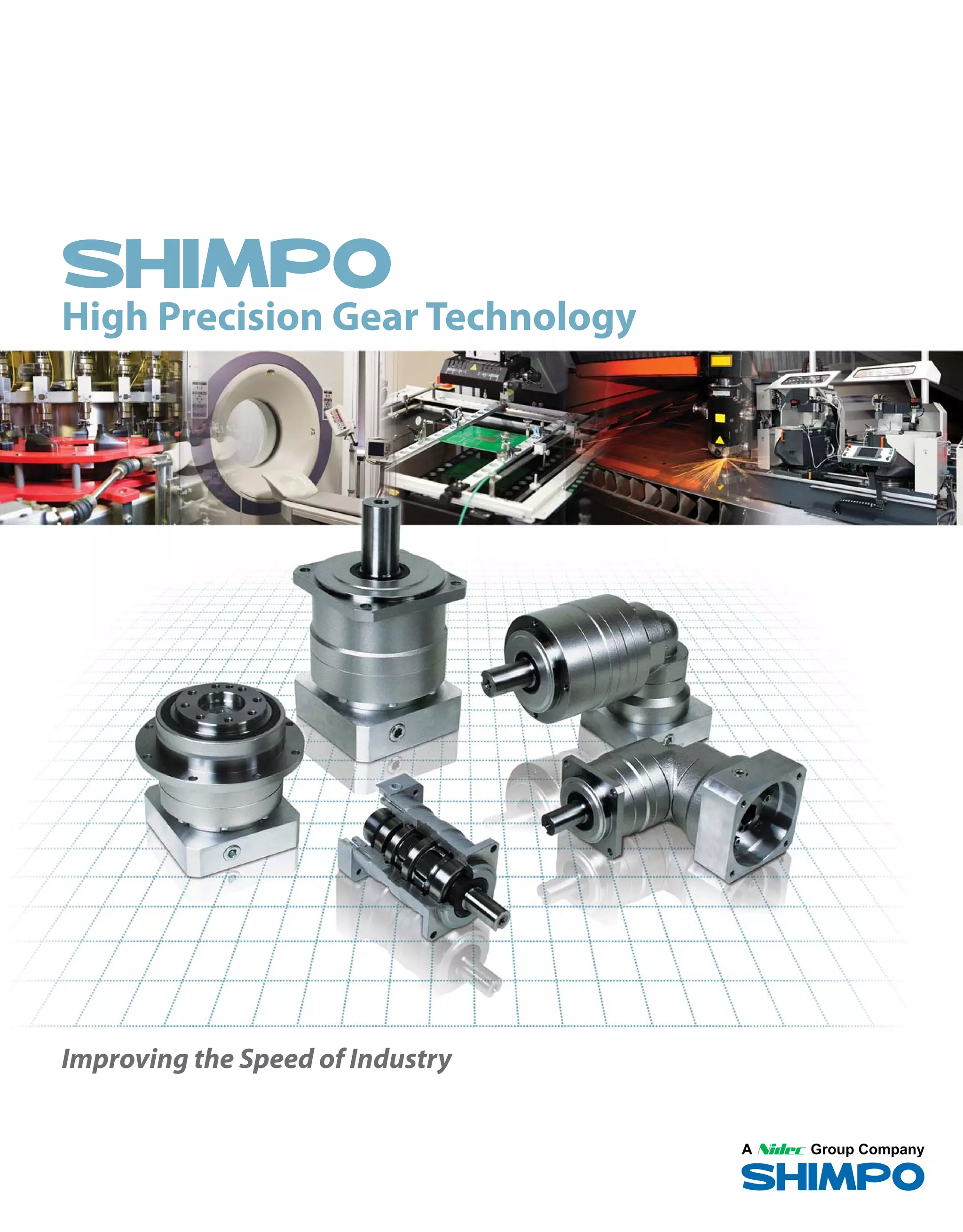
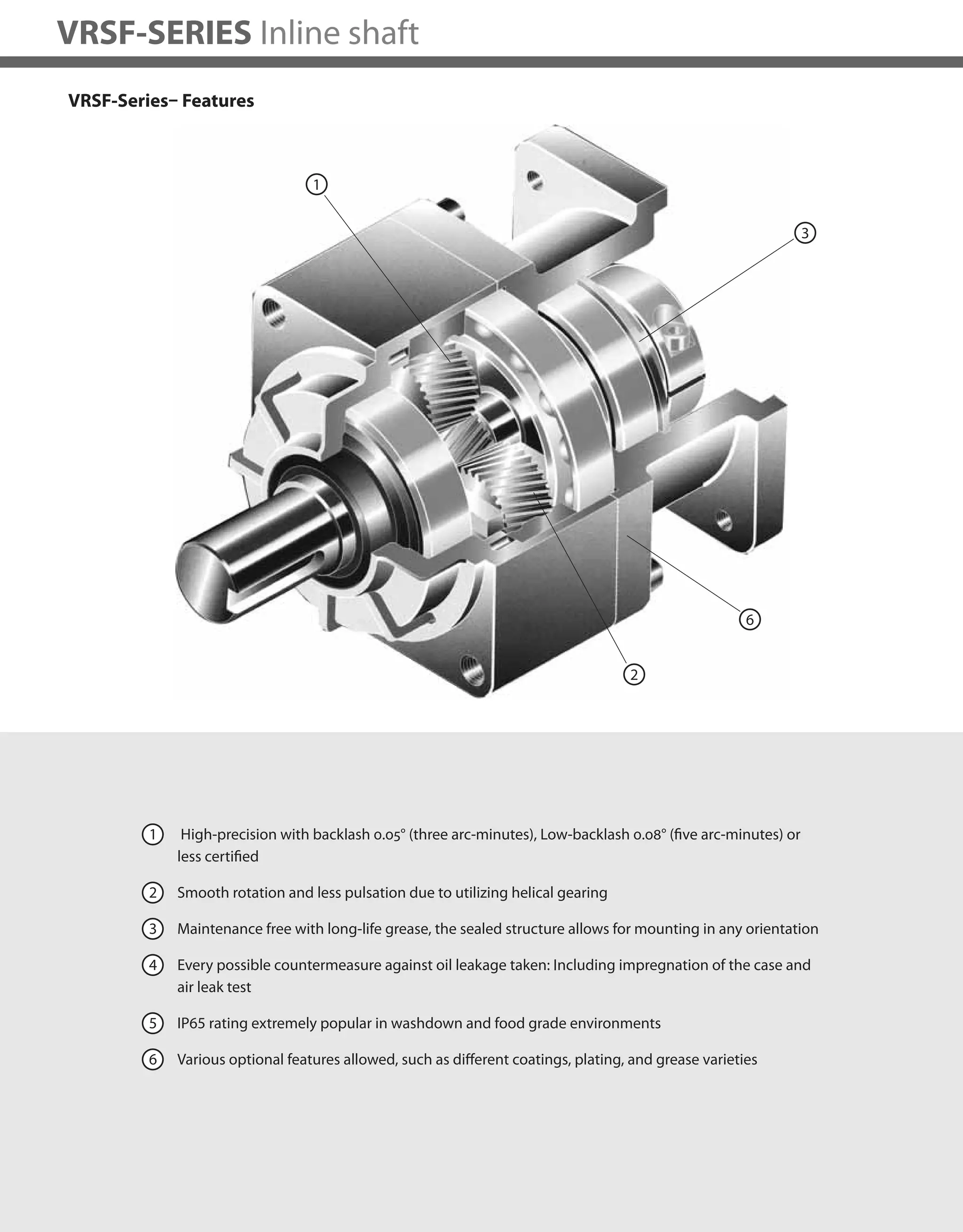
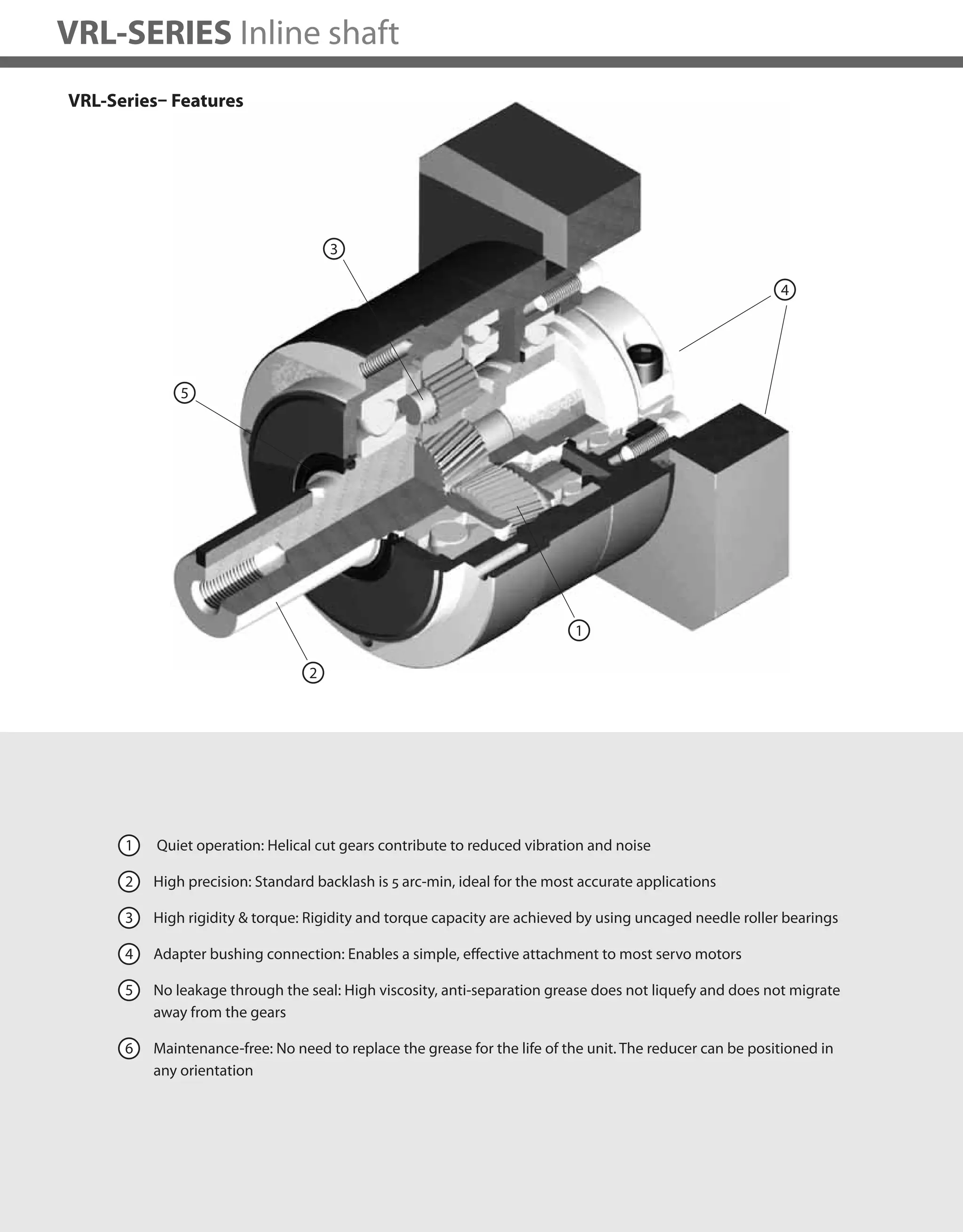
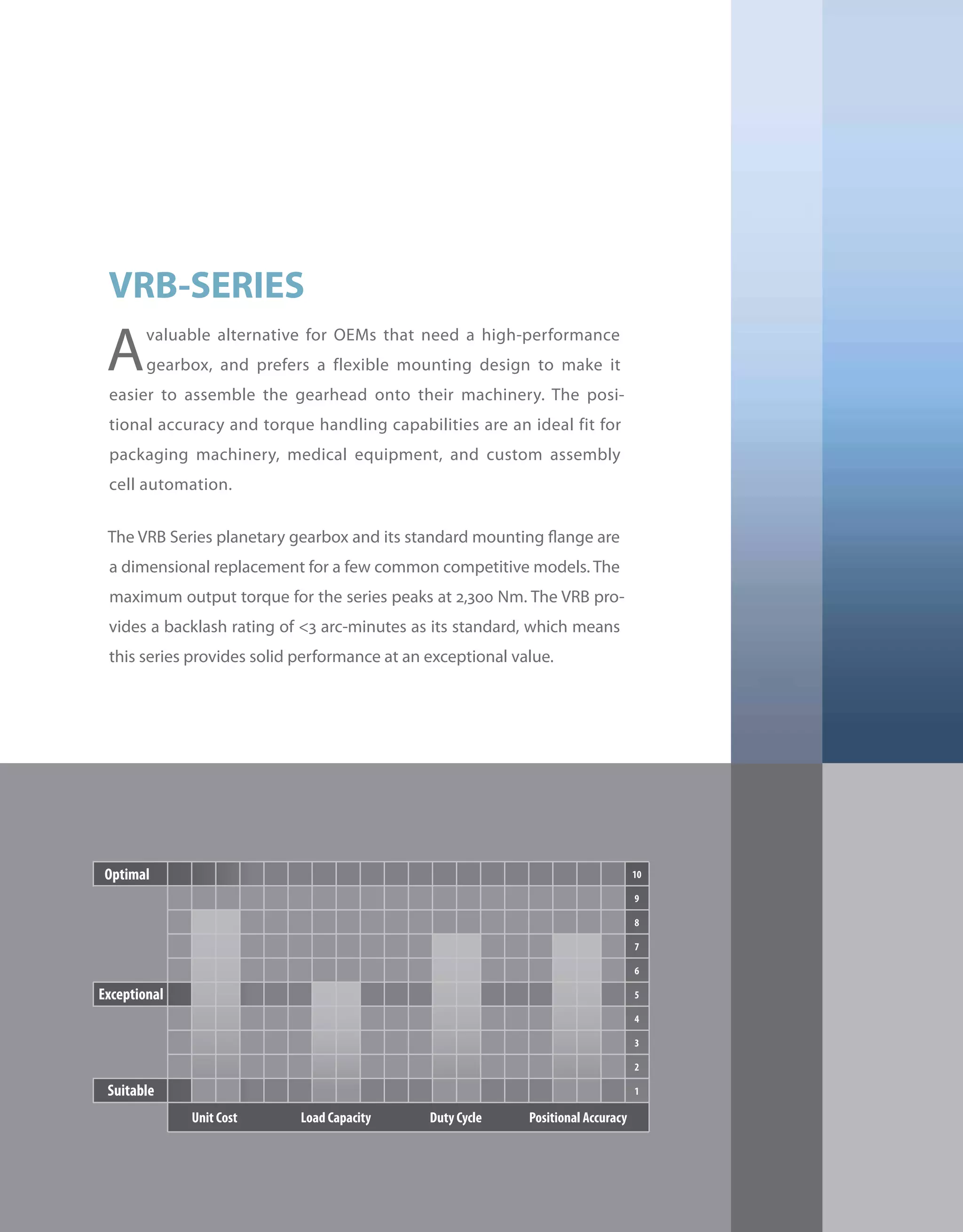
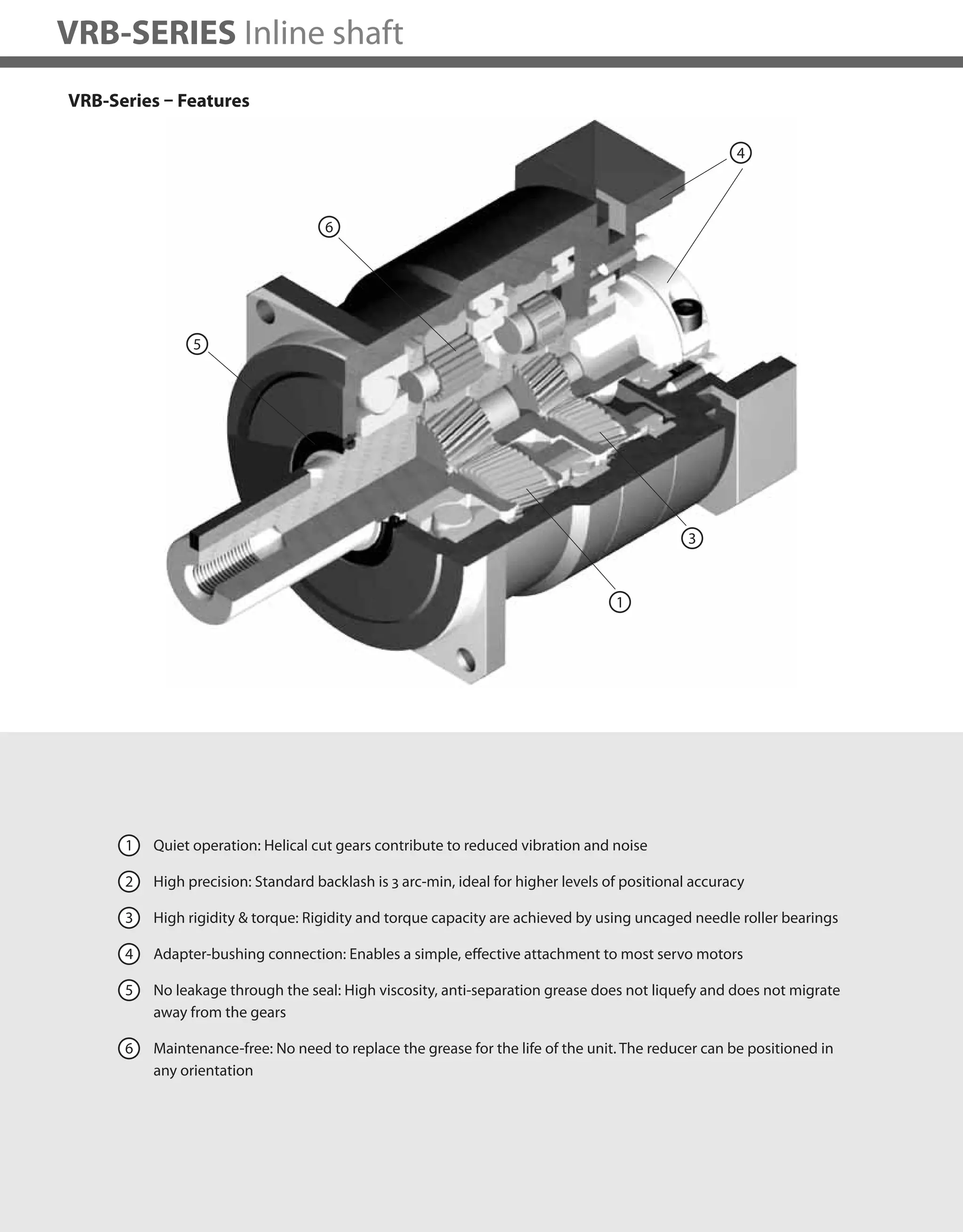
VRSF-SERIES Inline shaft
VRSF B-Frame – 1-Stage and 2-Stage Specifications
Frame Size B
Stage 1-Stage 2-Stage
Ratio Units Note 3 5 9 15 20 25 35
Nominal Output Torque [Nm] -- 3.43 2.84 2.35 4.02 5.00 6.27 3.84
Maximum Acceleration Torque [Nm] -- 10.3 8.53 7.25 12.2 15.0 19.0 11.5
Emergency Stop Torque [Nm] -- -- -- -- -- -- -- --
Nominal Input Speed [rpm] -- 3000 3000
Maximum Input Speed [rpm] *1 5000 5000
No Load Running Torque [Nm] -- 0.119 0.048
Permitted Radial Load [N] *2 392 490 588 784 804 882 882
Permitted Axial Load [N] *3 196 245 294 392 402 441 441
Moment of Inertia (≤Ø 8) [kgcm2] *4 0.081 0.059 0.052 0.057 0.056 0.056 0.052
Moment of Inertia (≤Ø 14) [kgcm2] *4 0.150 0.130 0.120 0.130 0.130 0.130 0.120
Efficiency [%] -- 90 85
Torsional Rigidity [Nm/arcmin] -- 0.8 0.8
Backlash (Standard) [Arc-min] -- ≤ 15 ≤ 15
Backlash (Low) [Arc-min] -- ≤ 10 ≤ 10
Backlash (Precision) [Arc-min] -- ≤ 3 ≤ 3
Noise Level [dB] -- ≤ 72 ≤ 65
Protection Class -- -- IP65 IP65
Ambient Temperature [°C] -- 0-40 0-40
Permitted Housing Temperature [°C] -- 90 90
Weight (≤Ø 8) [kg] *5 0.58 0.75
Weight (≤Ø 14) [kg] *5 0.7 0.86
*1) Nominal input speed is 3,000 rpm or less
*2) Permitted radial load is measured at the middle of the output shaft
*3) Permitted thrust load is measured at the center of the output shaft
*4) The moment of inertia is reflected to the input shaft of the reducer
*5) The weight varies slightly depending on the input bore size and reduction ratio
Refer to page 30-31 for Metric and NEMA Output Flange](https://image.slidesharecdn.com/shimpohighprecisioncatalog-140807090507-phpapp01/75/Shimpo-high-precision-catalog-20-2048.jpg)
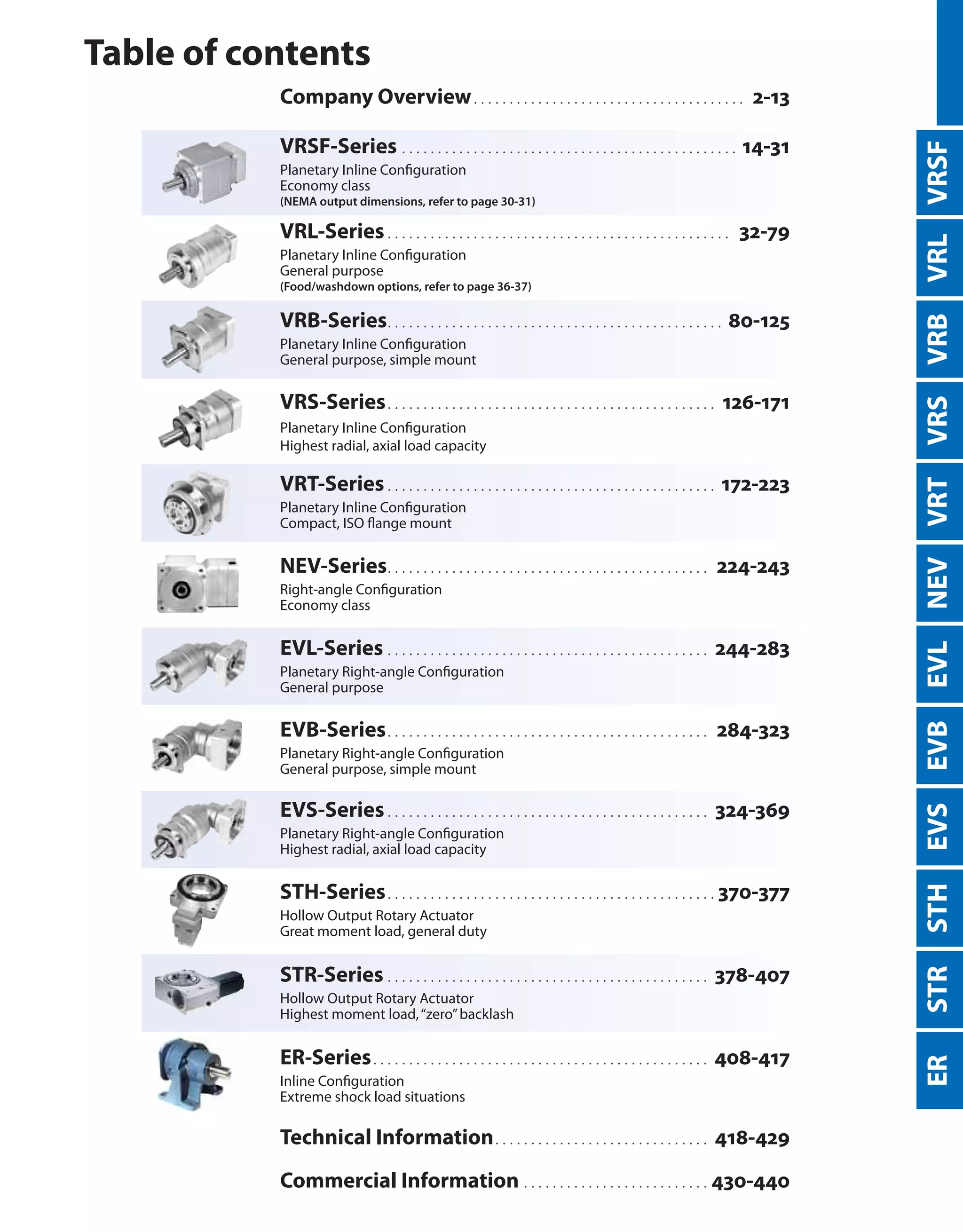
![19
VRSF
VRSF C-Frame – 1-Stage and 2-Stage Specifications
Frame Size C
Stage 1-Stage 2-Stage
Ratio Units Note 3 5 9 15 20 25 35 45 81
Nominal Output Torque [Nm] -- 6.86 11.5 9.7 16.2 21.1 26.4 15.5 9.5 9.7
Maximum Acceleration Torque [Nm] -- 20.6 34.3 29.2 48.6 63.3 79.2 46.6 28.6 29.2
Emergency Stop Torque [Nm] -- -- -- -- -- -- -- -- -- --
Nominal Input Speed [rpm] -- 3000 3000
Maximum Input Speed [rpm] *1 5000 5000
No Load Running Torque [Nm] -- 0.29 0.19
Permitted Radial Load [N] *2 784 980 1180 1470 1570 1670 1670 1670 1670
Permitted Axial Load [N] *3 392 490 588 735 785 833 833 833 833
Moment of Inertia (≤Ø 8) [kgcm2] *4 -- -- -- 0.077 0.070 0.062 0.055 0.053 0.052
Moment of Inertia (≤Ø 14) [kgcm2] *4 0.630 0.380 0.300 0.150 0.140 0.130 0.130 0.120 0.120
-- -- *4 1.100 0.880 0.800 -- -- -- -- -- --
Efficiency [%] -- 90 85
Torsional Rigidity [Nm/arcmin] -- 3 3
Backlash (Standard) [Arc-min] -- ≤ 15 ≤ 15
Backlash (Low) [Arc-min] -- ≤ 5 ≤ 5
Backlash (Precision) [Arc-min] -- ≤ 3 ≤ 3
Noise Level [dB] -- ≤ 72 ≤ 65
Protection Class -- -- IP 65 IP65
Ambient Temperature [°C] -- 0-40 0-40
Permitted Housing Temperature [°C] -- 90 90
Weight (≤Ø 8) [kg] *5 -- 1.8
Weight (≤Ø 14) [kg] *5 1.8 1.9
Weight (≤Ø 19) -- -- 2.2 --
*1) Nominal input speed is 3,000 rpm or less
*2) Permitted radial load is measured at the middle of the output shaft
*3) Permitted thrust load is measured at the center of the output shaft
*4) The moment of inertia is reflected to the input shaft of the reducer
*5) The weight varies slightly depending on the input bore size and reduction ratio
Refer to page 30-31 for Metric and NEMA Output Flange](https://image.slidesharecdn.com/shimpohighprecisioncatalog-140807090507-phpapp01/75/Shimpo-high-precision-catalog-21-2048.jpg)
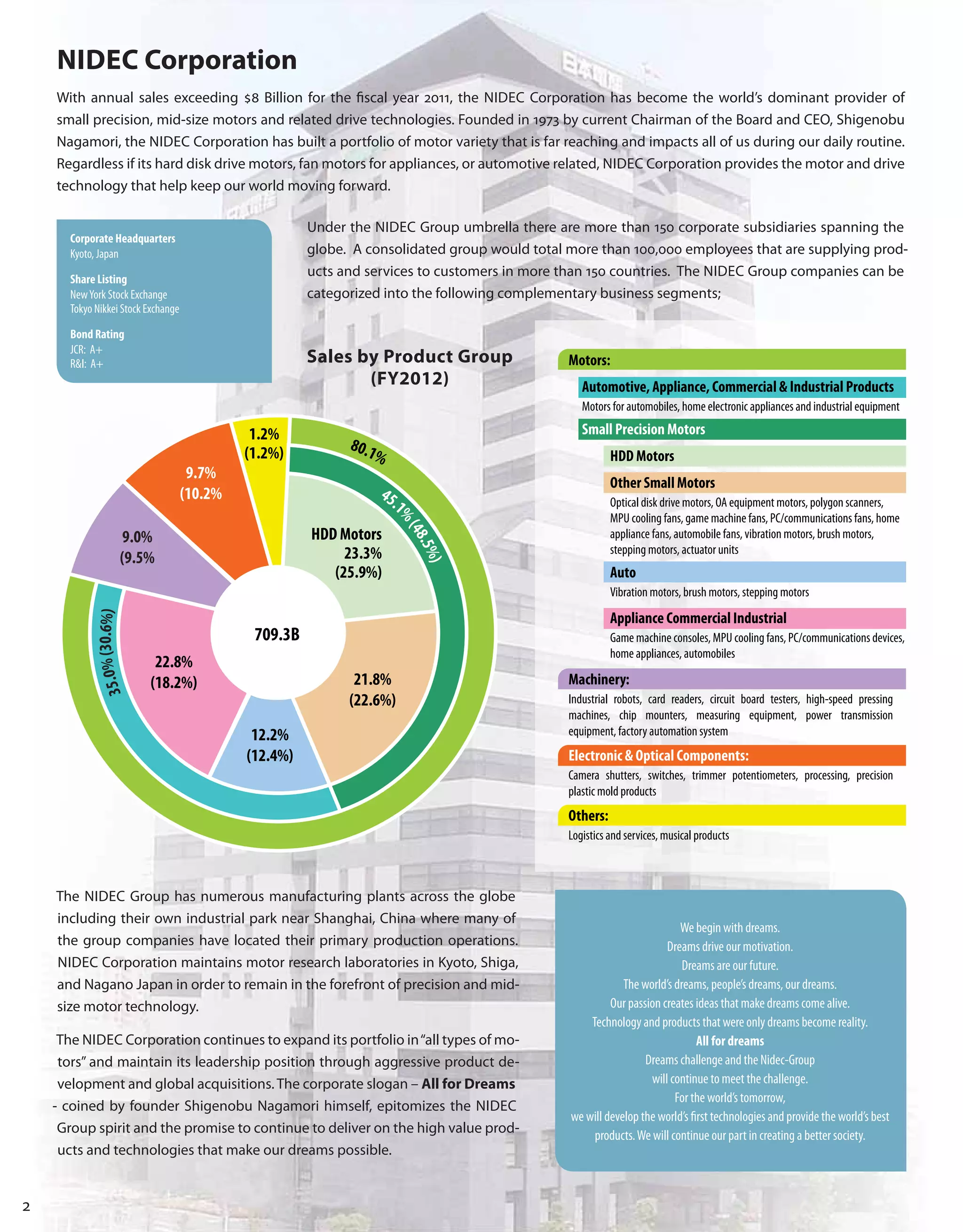
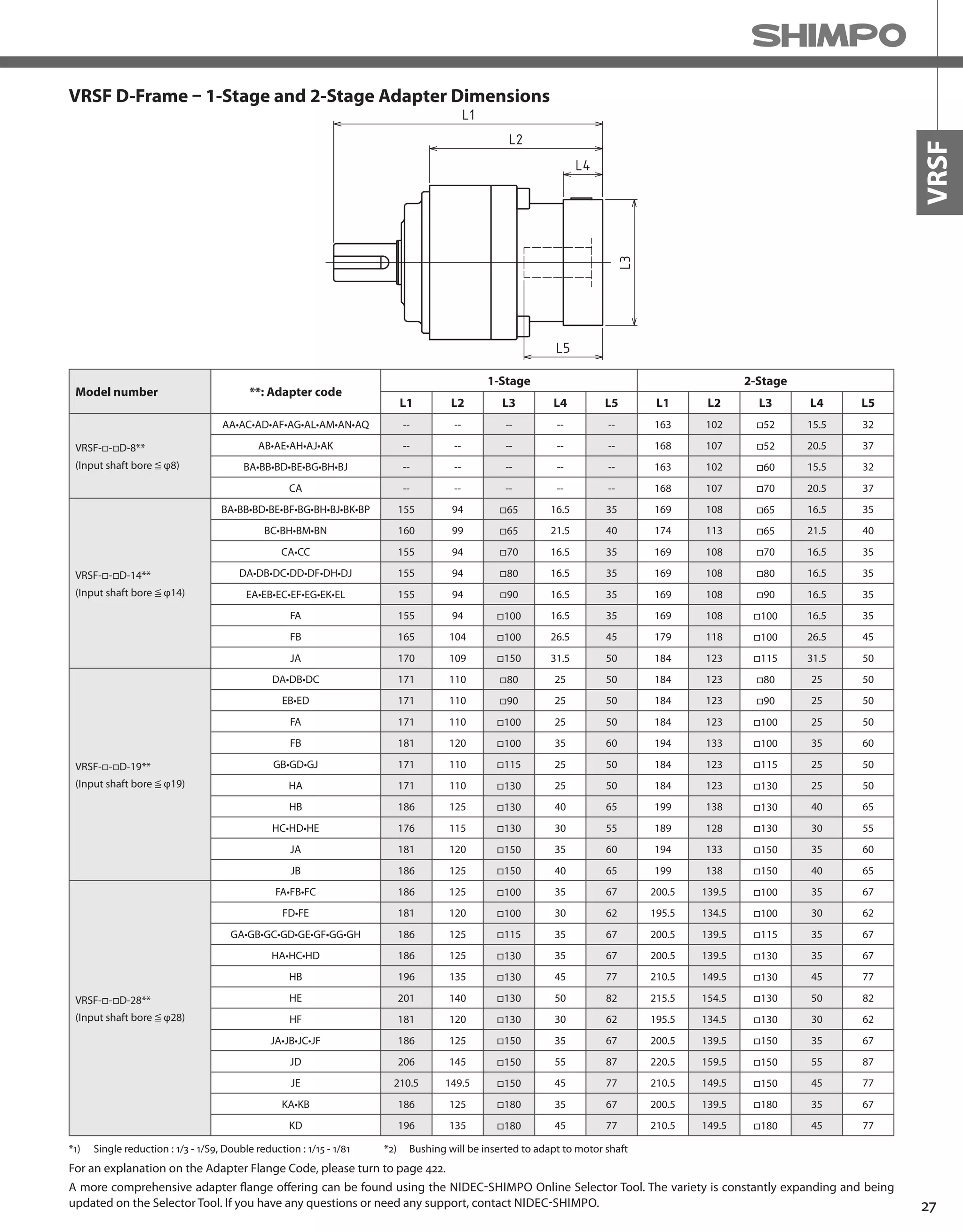
![20
VRSF-SERIES Inline shaft
VRSF D-Frame – 1-Stage and 2-Stage Specifications
*1) Nominal input speed is 3,000 rpm or less
*2) Permitted radial load is measured at the middle of the output shaft
*3) Permitted thrust load is measured at the center of the output shaft
*4) The moment of inertia is reflected to the input shaft of the reducer
*5) The weight varies slightly depending on the input bore size and reduction ratio
Frame Size D
Stage 1-Stage 2-Stage
Ratio Units Note 3 5 9 15 20 25 35 45 81
Nominal Output Torque [Nm] -- 18.3 23.5 18.2 30.4 40.6 50.7 37 28.3 17.8
Maximum Acceleration Torque [Nm] -- 54.9 70.6 54.7 91.2 122 152 111 85.2 53.5
Emergency Stop Torque [Nm] -- -- -- -- -- -- -- -- -- --
Nominal Input Speed [rpm] -- 3000 3000
Maximum Input Speed [rpm] *1 5000 5000
No Load Running Torque [Nm] -- 0.51 0.26
Permitted Radial Load [N] *2 882 1080 1470 1760 1910 2060 2060 2060 2060
Permitted Axial Load [N] *3 441 539 735 882 955 1030 1030 1030 1030
Moment of Inertia (≤Ø 8) [kgcm2] *4 -- -- -- -- -- -- -- -- 0.10
Moment of Inertia (≤Ø 14) [kgcm2] *4 1.30 0.59 0.38 0.37 0.35 0.34 0.30 0.29 0.29
Moment of Inertia (≤Ø 19) [kgcm2] *4 1.80 1.10 0.90 0.86 0.84 0.83 0.79 0.78 0.77
Moment of Inertia (≤Ø 28) [kgcm2] *4 3.60 2.90 2.70 2.70 2.70 2.70 -- -- --
Efficiency [%] -- 90 85
Torsional Rigidity [Nm/arcmin] -- 6 6
Backlash (Standard) [Arc-min] -- ≤ 15 ≤ 15
Backlash (Low) [Arc-min] -- ≤ 5 ≤ 5
Backlash (Precision) [Arc-min] -- ≤ 3 ≤ 3
Noise Level [dB] -- ≤ 72 ≤ 65
Protection Class -- -- IP65 IP65
Ambient Temperature [°C] -- 0-40 0-40
Permitted Housing Temperature [°C] -- 90 90
Weight (≤Ø 8) [kg] *5 -- 2.8
Weight (≤Ø 14) [kg] *5 2.8 3.3
Weight (≤Ø 19) [kg] *5 3.2 3.7
Weight (≤Ø 28) [kg] *5 4.0 4.8
Refer to page 30-31 for Metric and NEMA Output Flange](https://image.slidesharecdn.com/shimpohighprecisioncatalog-140807090507-phpapp01/75/Shimpo-high-precision-catalog-22-2048.jpg)
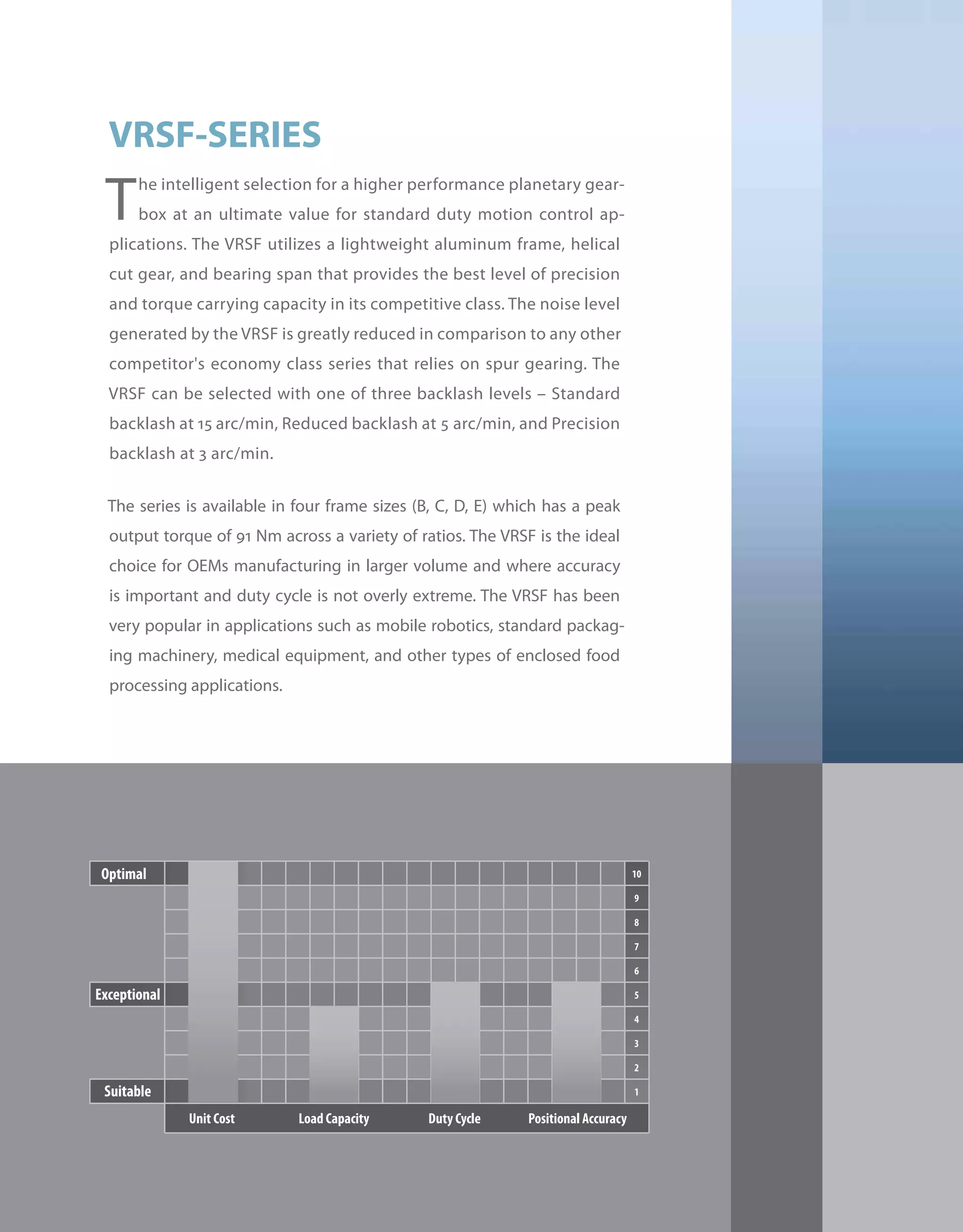
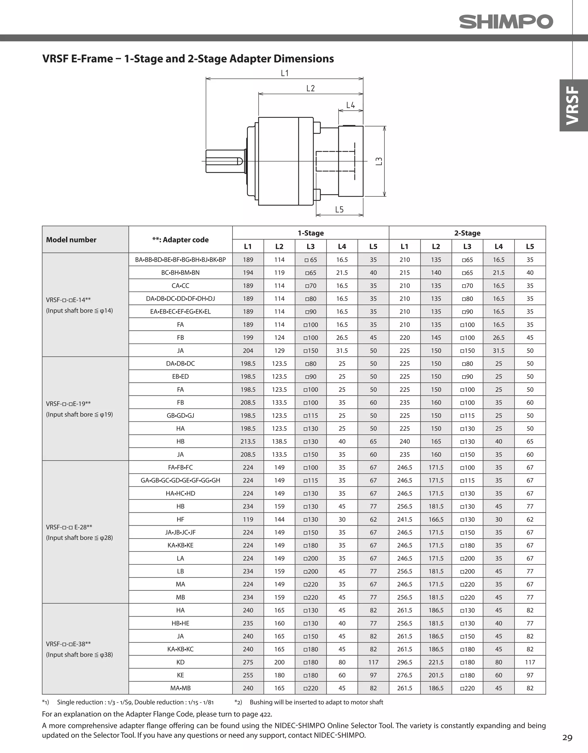
![21
VRSF
VRSF E-Frame – 1-Stage and 2-Stage Specifications
*1) Nominal input speed is 3,000 rpm or less
*2) Permitted radial load is measured at the middle of the output shaft
*3) Permitted thrust load is measured at the center of the output shaft
*4) The moment of inertia is reflected to the input shaft of the reducer
*5) The weight varies slightly depending on the input bore size and reduction ratio
Frame Size E
Stage 1-Stage 2-Stage
Ratio Units Note 3 5 9 15 20 25 35 45 81
Nominal Output Torque [Nm] -- 44.1 56.8 73.5 91.4 78.4 65.4 71 91.3 43.3
Maximum Acceleration Torque [Nm] -- 132 171 221 274 235 196 213 274 130
Emergency Stop Torque [Nm] -- -- -- -- -- -- -- -- -- --
Nominal Input Speed [rpm] -- 3000 3000
Maximum Input Speed [rpm] *1 5000 5000
No Load Running Torque [Nm] -- 1.12 0.62
Permitted Radial Load [N] *2 1370 1670 1960 2350 2500 2650 3430 3520 3530
Permitted Axial Load [N] *3 686 833 980 1180 1250 1320 1715 1760 1765
Moment of Inertia (≤Ø 8) [kgcm2] *4 -- -- 0.61 0.63 0.56 0.53 0.40 0.35 0.34
Moment of Inertia (≤Ø 14) [kgcm2] *4 4.40 1.90 1.20 1.10 1.10 1.00 0.90 0.85 0.84
Moment of Inertia (≤Ø 19) [kgcm2] *4 6.20 3.70 2.90 3.30 3.20 3.20 2.80 2.70 2.70
Moment of Inertia (≤Ø 28) [kgcm2] *4 14.00 11.00 11.00 11.00 11.00 11.00 -- -- --
Efficiency [%] -- 90 85
Torsional Rigidity [Nm/arcmin] -- 20 20
Backlash (Standard) [Arc-min] -- ≤ 15 ≤ 15
Backlash (Low) [Arc-min] -- ≤ 5 ≤ 5
Backlash (Precision) [Arc-min] -- ≤ 3 ≤ 3
Noise Level [dB] -- ≤ 75 ≤ 75
Protection Class -- -- IP65 IP65
Ambient Temperature [°C] -- 0-40 0-40
Permitted Housing Temperature [°C] -- 90 90
Weight (≤Ø 8) [kg] *5 6.1 7.1
Weight (≤Ø 14) [kg] *5 6.5 7.5
Weight (≤Ø 19) [kg] *5 7.4 9.3
Weight (≤Ø 28) [kg] *5 9.8 11.7
Refer to page 30-31 for Metric and NEMA Output Flange](https://image.slidesharecdn.com/shimpohighprecisioncatalog-140807090507-phpapp01/75/Shimpo-high-precision-catalog-23-2048.jpg)


![38
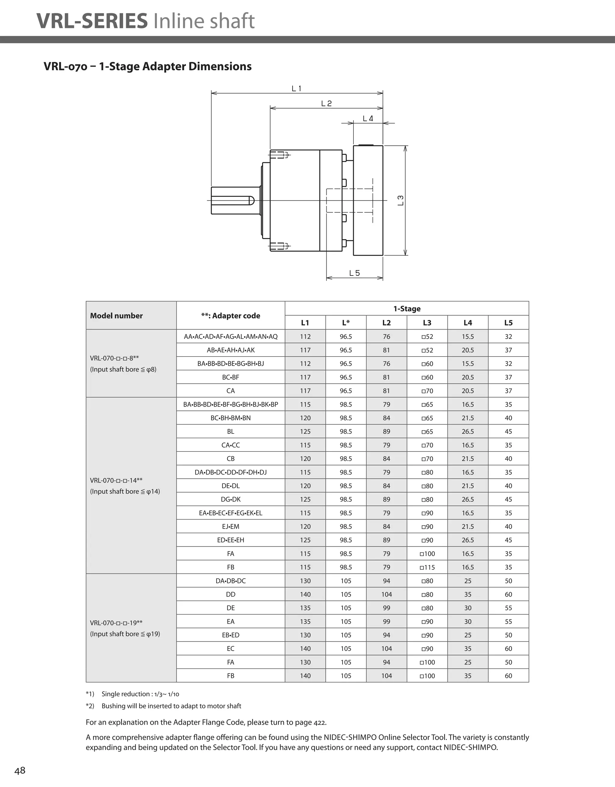
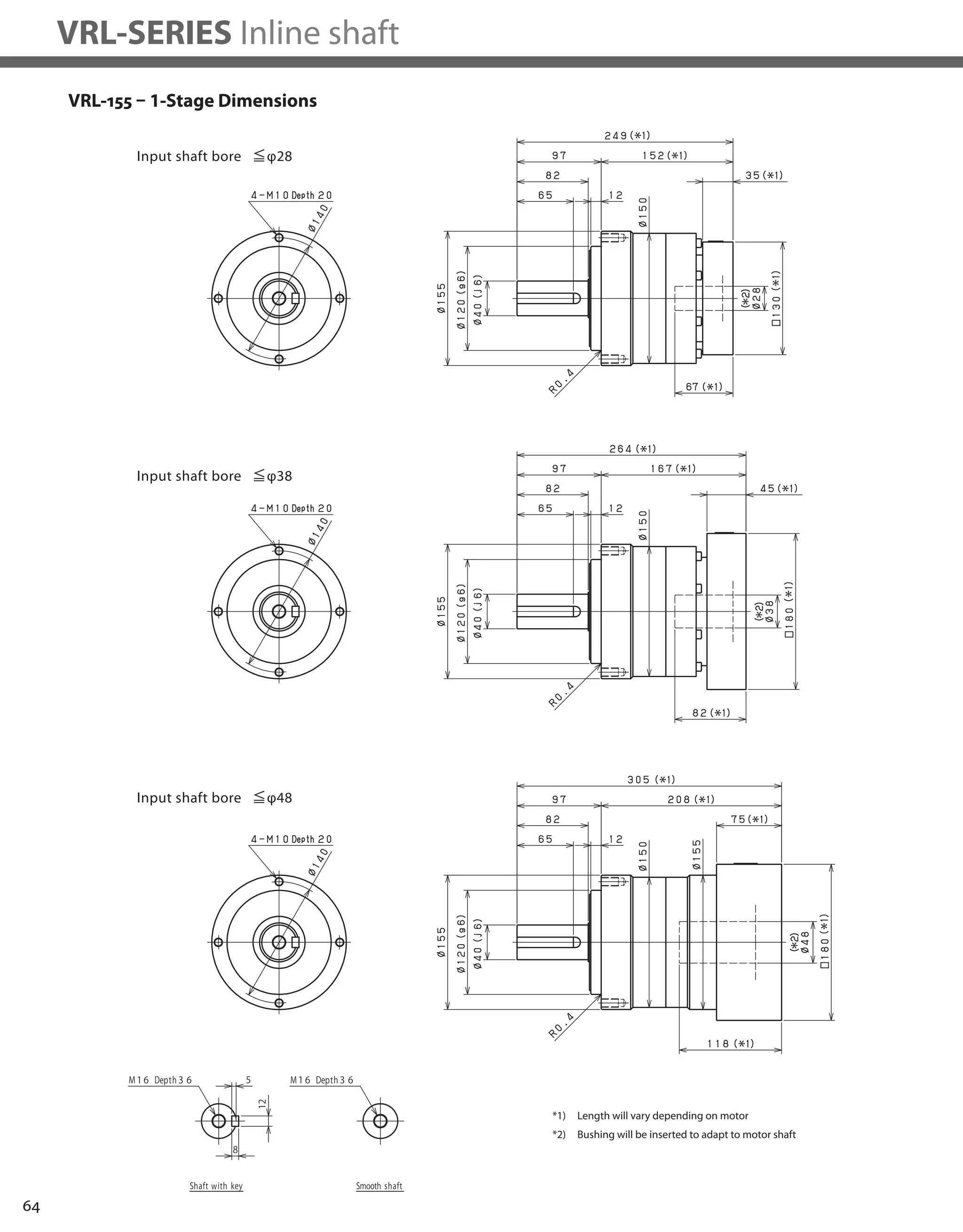
VRL-SERIES Inline shaft
VRL-050 – 1-Stage Specifications
Frame Size 050
Stage 1-Stage
Ratio Units Note 3 4 5 6 7 8 9 10
Nominal Output Torque [Nm] *1 6 9 9 9 9 9 6 6
Maximum Acceleration Torque [Nm] *2 12 18 18 18 18 18 12 12
Emergency Stop Torque [Nm] *3 30 35 35 35 35 35 30 30
Nominal Input Speed [rpm] *4 4000
Maximum Input Speed [rpm] *5 8000
No Load Running Torque [Nm] *6 0.03
Permitted Radial Load [N] *7 240 270 290 310 320 340 350 360
Permitted Axial Load [N] *8 270 300 330 360 380 410 430 450
Maximum Radial Load [N] *9 710
Maximum Axial Load [N] *10 640
Moment of Inertia (≤Ø 8) [kgcm2] -- 0.053 0.041 0.036 0.034 0.032 0.031 0.031 0.030
Moment of Inertia (≤ Ø 14) [kgcm2] -- 0.091 0.079 0.074 0.072 0.071 0.070 0.069 0.069
Efficiency [%] *11 95
Torsional Rigidity [Nm/arc-min] *12 2
Maximum Torsional Backlash [arc-min] -- ≤ 5
Noise Level [dB] *13 61
Protection Class -- *14 IP54 (IP65)
Ambient Temperature [°C] -- 0-40
Permitted Housing Temperature [°C] -- 90
Weight [kg] *15 0.7
Frame Size 050
Stage 2-Stage
Ratio Units Note 15 16 20 25 28 30 35 40
Nominal Output Torque [Nm] *1 6 9 9 9 9 9 9 9
Maximum Acceleration Torque [Nm] *2 12 18 18 18 18 12 18 18
Emergency Stop Torque [Nm] *3 30 35 35 35 35 30 35 35
Nominal Input Speed [rpm] *4 4000
Maximum Input Speed [rpm] *5 8000
No Load Running Torque [Nm] *6 0.01
Permitted Radial Load [N] *7 410 420 460 490 510 520 550 570
Permitted Axial Load [N] *8 540 550 610 640 640 640 640 640
Maximum Radial Load [N] *9 710
Maximum Axial Load [N] *10 640
Moment of Inertia (≤Ø 8) [kgcm2] -- 0.035 0.038 0.034 0.034 0.038 0.030 0.034 0.030
Moment of Inertia (≤ Ø 14) [kgcm2] -- -- -- -- -- -- -- -- --
Efficiency [%] *11 90
Torsional Rigidity [Nm/arc-min] *12 2
Maximum Torsional Backlash [arc-min] -- ≤ 7
Noise Level [dB] *13 61
Protection Class -- *14 IP54 (IP65)
Ambient Temperature [°C] -- 0-40
Permitted Housing Temperature [°C] -- 90
Weight [kg] *15 0.8
VRL-050 – 2-Stage Specifications](https://image.slidesharecdn.com/shimpohighprecisioncatalog-140807090507-phpapp01/75/Shimpo-high-precision-catalog-40-2048.jpg)
![39
VRL
Frame Size 050
Stage 2-Stage
Ratio Units Note 45 50 60 70 80 90 100
Nominal Output Torque [Nm] *1 6 9 9 9 9 6 6
Maximum Acceleration Torque [Nm] *2 12 18 18 18 18 12 12
Emergency Stop Torque [Nm] *3 30 35 35 35 35 30 30
Nominal Input Speed [rpm] *4 4000
Maximum Input Speed [rpm] *5 8000
No Load Running Torque [Nm] *6 0.01
Permitted Radial Load [N] *7 600 620 660 690 710 710 710
Permitted Axial Load [N] *8 640 640 640 640 640 640 640
Maximum Radial Load [N] *9 710
Maximum Axial Load [N] *10 640
Moment of Inertia (≤Ø 8) [kgcm2] -- 0.034 0.030 0.030 0.030 0.030 0.030 0.030
Moment of Inertia (≤ Ø 14) [kgcm2] -- -- -- -- -- -- -- --
Efficiency [%] *11 90
Torsional Rigidity [Nm/arc-min] *12 2
Maximum Torsional Backlash [arc-min] -- ≤ 7
Noise Level [dB] *13 61
Protection Class -- *14 IP54 (IP65)
Ambient Temperature [°C] -- 0-40
Permitted Housing Temperature [°C] -- 90
Weight [kg] *15 0.8
*1) At nominal input speed, service life is 20,000 hours
*2) The maximum torque when starting or stopping operation
*3) The maximum torque allowed under a stress situation (Permitted 1,000 times during service life)
*4) The average input speed
*5) The maximum intermittent input speed
*6) This is the torque at no load applied on the input shaft. The input speed is 4,000 rpm for VRL 050
*7) At this load and nominal input speed, service life will be 20,000 hours. (The radial load applied to the output side bearing)
*8) At this load and nominal input speed, service life will be 20,000 hours. (The axial load applied to the output shaft center)
*9) The maximum radial load that the reducer can accept
*10) The maximum axial load that the reducer can accept
*11) The efficiency at the nominal torque rating
*12) This does not include the lost motion
*13) Contact NIDEC-SHIMPO for the testing conditions and environment
*14) IP65 (wash-down) is available as an option. Contact NIDEC-SHIMPO for more details and our food grade options
*15) The weight may vary slightly between models
VRL-050 – 2-Stage Specifications](https://image.slidesharecdn.com/shimpohighprecisioncatalog-140807090507-phpapp01/75/Shimpo-high-precision-catalog-41-2048.jpg)


![44
VRL-SERIES Inline shaft
VRL-070 – 1-Stage Specifications
VRL-070 – 2-Stage Specifications
Frame Size 070
Stage 1-Stage
Ratio Unit Note 3 4 5 6 7 8 9 10
Nominal Output Torque [Nm] *1 18 27 27 27 27 27 18 18
Maximum Output Torque [Nm] *2 35 50 50 50 50 50 35 35
Emergency Stop Torque [Nm] *3 80 100 100 100 100 100 80 80
Nominal Input Speed [rpm] *4 3000
Maximum Input Speed [rpm] *5 6000
No Load Running Torque [Nm] *6 0.08
Permitted Radial Load [N] *7 430 470 510 540 570 600 620 640
Permitted Axial Load [N] *8 310 360 390 430 460 480 510 530
Maximum Radial Load [N] *9 1200
Maximum Axial Load [N] *10 1100
Moment of Inertia (≤Ø 8) [kgcm2] -- 0.140 0.095 0.077 0.068 0.062 0.059 0.057 0.056
Moment of Inertia (≤ Ø 14) [kgcm2] -- 0.220 0.170 0.160 0.150 0.140 0.140 0.140 0.140
Moment of Inertia (≤ Ø 19) [kgcm2] -- 0.430 0.380 0.360 0.360 0.350 0.350 0.340 0.340
Efficiency [%] *11 95
Torsional Rigidity [Nm/arcmin] *12 3
Maximum Torsional Backlash [Arc-min] -- ≤ 5
Noise Level [dB] *13 ≤ 66
Protection Class -- *14 IP54 (IP65)
Ambient Temperature [°C] -- 0-40
Permitted Housing Temperature [°C] -- 90
Weight [kg] *15 1.5
Frame Size 070
Stage 2-Stage
Ratio Unit Note 15 16 20 25 28 30 35 40
Nominal Output Torque [Nm] *1 18 27 27 27 27 18 27 27
Maximum Output Torque [Nm] *2 35 50 50 50 50 35 50 50
Emergency Stop Torque [Nm] *3 80 100 100 100 100 80 100 100
Nominal Input Speed [rpm] *4 3000
Maximum Input Speed [rpm] *5 6000
No Load Running Torque [Nm] *6 0.04
Permitted Radial Load [N] *7 740 750 810 870 910 930 980 1000
Permitted Axial Load [N] *8 630 650 720 790 830 860 920 970
Maximum Radial Load [N] *9 1200
Maximum Axial Load [N] *10 1100
Moment of Inertia (≤Ø 8) [kgcm2] -- 0.055 0.057 0.054 0.053 0.055 0.049 0.053 0.049
Moment of Inertia (≤ Ø 14) [kgcm2] -- 0.140 0.140 0.130 0.130 0.140 0.130 0.130 0.130
Moment of Inertia (≤ Ø 19) [kgcm2] -- 0.350 0.360 0.350 0.350 0.360 0.340 0.350 0.340
Efficiency [%] *11 90
Torsional Rigidity [Nm/arcmin] *12 3
Maximum Torsional Backlash [Arc-min] -- ≤ 5
Noise Level [dB] *13 ≤ 66
Protection Class -- *14 IP54 (IP65)
Ambient Temperature [°C] -- 0-40
Permitted Housing Temperature [°C] -- 90
Weight [kg] *15 1.7](https://image.slidesharecdn.com/shimpohighprecisioncatalog-140807090507-phpapp01/75/Shimpo-high-precision-catalog-46-2048.jpg)
![45
VRL
*1) At nominal input speed, service life is 20,000 hours
*2) The maximum torque when starting or stopping operation
*3) The maximum torque allowed under a stress situation (Permitted 1,000 times during service life)
*4) The average input speed
*5) The maximum intermittent input speed
*6) This is the torque at no load applied on the input shaft. The input speed is 3,000 rpm for VRL 070
*7) At this load and nominal input speed, service life will be 20,000 hours. (The radial load applied to the output side bearing)
*8) At this load and nominal input speed, service life will be 20,000 hours. (The axial load applied to the output shaft center)
*9) The maximum radial load that the reducer can accept
*10) The maximum axial load that the reducer can accept
*11) The efficiency at the nominal torque rating
*12) This does not include the lost motion
*13) Contact NIDEC-SHIMPO for the testing conditions and environment
*14) IP65 (wash-down) is available as an option. Contact NIDEC-SHIMPO for more details and our food grade options
*15) The weight may vary slightly between models
VRL-070 – 2-Stage Specifications
Frame Size 070
Stage 2-Stage
Ratio Unit Note 45 50 60 70 80 90 100
Nominal Output Torque [Nm] *1 18 27 27 27 27 18 18
Maximum Output Torque [Nm] *2 35 50 50 50 50 35 35
Emergency Stop Torque [Nm] *3 80 100 100 100 100 80 80
Nominal Input Speed [rpm] *4 3000
Maximum Input Speed [rpm] *5 6000
No Load Running Torque [Nm] *6 0.04
Permitted Radial Load [N] *7 1100 1100 1200 1200 1200 1200 1200
Permitted Axial Load [N] *8 1000 1100 1100 1100 1100 1100 1100
Maximum Radial Load [N] *9 1200
Maximum Axial Load [N] *10 1100
Moment of Inertia (≤Ø 8) [kgcm2] -- 0.053 0.049 0.049 0.049 0.049 0.049 0.049
Moment of Inertia (≤ Ø 14) [kgcm2] -- 0.130 0.130 0.130 0.130 0.130 0.13 0.13
Moment of Inertia (≤ Ø 19) [kgcm2] -- 0.350 0.340 0.340 0.340 0.340 0.340 0.340
Efficiency [%] *11 90
Torsional Rigidity [Nm/arcmin] *12 3
Maximum Torsional Backlash [Arc-min] -- ≤ 5
Noise Level [dB] *13 ≤ 66
Protection Class -- *14 IP54 (IP65)
Ambient Temperature [°C] -- 0-40
Permitted Housing Temperature [°C] -- 90
Weight [kg] *15 1.7](https://image.slidesharecdn.com/shimpohighprecisioncatalog-140807090507-phpapp01/75/Shimpo-high-precision-catalog-47-2048.jpg)


![50
VRL-SERIES Inline shaft
Frame Size 090
Stage 1-Stage
Ratio Unit Note 3 4 5 6 7 8 9 10
Nominal Output Torque [Nm] *1 50 75 75 75 75 75 50 50
Maximum Acceleration Torque [Nm] *2 80 125 125 125 125 125 80 80
Emergency Stop Torque [Nm] *3 200 250 250 250 250 250 200 200
Nominal Input Speed [rpm] *4 3000
Maximum Input Speed [rpm] *5 6000
No Load Running Torque [Nm] *6 0.35
Permitted Radial Load [N] *7 810 890 960 1000 1100 1100 1200 1200
Permitted Axial Load [N] *8 930 1100 1200 1300 1300 1400 1500 1600
Maximum Radial Load [N] *9 2400
Maximum Axial Load [N] *10 2200
Moment of Inertia (≤Ø 8) [kgcm2] -- -- -- -- -- -- -- -- --
Moment of Inertia (≤ Ø 14) [kgcm2] -- 0.720 0.490 0.400 0.360 0.320 0.310 0.290 0.290
Moment of Inertia (≤ Ø 19) -- -- 1.200 0.950 0.860 0.820 0.790 0.770 0.760 0.750
Moment of Inertia (≤ Ø 28) [kgcm2] -- 3.200 3.000 2.900 2.800 2.800 2.800 2.800 2.800
Efficiency [%] *11 95
Torsional Rigidity [Nm/arc-min] *12 10
Maximum Torsional Backlash [arc-min] -- ≤ 5
Noise Level [dB] *13 67
Protection Class -- *14 IP54 (IP65)
Ambient Temperature [°C] -- 0-40
Permitted Housing Temperature [°C] -- 90
Weight [kg] *15 3.5
Frame Size 090
Stage 2-Stage
Ratio Unit Note 15 16 20 25 28 30 35 40
Nominal Output Torque [Nm] *1 50 75 75 75 75 50 75 75
Maximum Acceleration Torque [Nm] *2 80 125 125 125 125 80 125 125
Emergency Stop Torque [Nm] *3 200 250 250 250 250 200 250 250
Nominal Input Speed [rpm] *4 3000
Maximum Input Speed [rpm] *5 6000
No Load Running Torque [Nm] *6 0.06
Permitted Radial Load [N] *7 1400 1400 1500 1600 1700 1700 1800 1900
Permitted Axial Load [N] *8 1900 1900 2100 2200 2200 2200 2200 2200
Maximum Radial Load [N] *9 2400
Maximum Axial Load [N] *10 2200
Moment of Inertia (≤Ø 8) [kgcm2] -- 0.130 0.150 0.130 0.120 0.140 0.100 0.120 0.099
Moment of Inertia (≤ Ø 14) [kgcm2] -- 0.280 0.300 0.280 0.280 0.290 0.250 0.270 0.250
Moment of Inertia (≤ Ø 19) -- -- 0.720 0.740 0.720 0.710 0.730 0.700 0.710 0.700
Moment of Inertia (≤ Ø 28) [kgcm2] -- 2.700 2.800 2.700 2.700 2.700 2.600 2.700 2.600
Efficiency [%] *11 90
Torsional Rigidity [Nm/arc-min] *12 10
Maximum Torsional Backlash [arc-min] -- ≤ 5
Noise Level [dB] *13 67
Protection Class -- *14 IP54 (IP65)
Ambient Temperature [°C] -- 0-40
Permitted Housing Temperature [°C] -- 90
Weight [kg] *15 4
VRL-090 – 1-Stage Specifications
VRL-090 – 2-Stage Specifications](https://image.slidesharecdn.com/shimpohighprecisioncatalog-140807090507-phpapp01/75/Shimpo-high-precision-catalog-52-2048.jpg)
![51
VRL
Frame Size 090
Stage 2-Stage
Ratio Unit Note 45 50 60 70 80 90 100
Nominal Output Torque [Nm] *1 50 75 75 75 75 50 50
Maximum Acceleration Torque [Nm] *2 80 125 125 125 125 80 80
Emergency Stop Torque [Nm] *3 200 250 250 250 250 200 200
Nominal Input Speed [rpm] *4 3000
Maximum Input Speed [rpm] *5 6000
No Load Running Torque [Nm] *6 0.06
Permitted Radial Load [N] *7 2000 2100 2200 2300 2400 2400 2400
Permitted Axial Load [N] *8 2200 2200 2200 2200 2200 2200 2200
Maximum Radial Load [N] *9 2400
Maximum Axial Load [N] *10 2200
Moment of Inertia (≤Ø 8) [kgcm2] -- 0.120 0.098 0.098 0.097 0.097 0.097 0.097
Moment of Inertia (≤ Ø 14) [kgcm2] -- 0.270 0.250 0.250 0.250 0.250 0.250 0.250
Moment of Inertia (≤ Ø 19) -- -- 0.710 0.690 0.690 0.690 0.690 0.690 0.690
Moment of Inertia (≤ Ø 28) [kgcm2] -- 2.700 2.600 2.600 2.600 2.600 2.600 2.600
Efficiency [%] *11 90
Torsional Rigidity [Nm/arc-min] *12 10
Maximum Torsional Backlash [arc-min] -- ≤ 5
Noise Level [dB] *13 67
Protection Class -- *14 IP54 (IP65)
Ambient Temperature [°C] -- 0-40
Permitted Housing Temperature [°C] -- 90
Weight [kg] *15 4
VRL-090 – 2-Stage Specifications
*1) At nominal input speed, service life is 20,000 hours
*2) The maximum torque when starting or stopping operation
*3) The maximum torque allowed under a stress situation (Permitted 1,000 times during service life)
*4) The average input speed
*5) The maximum intermittent input speed
*6) This is the torque at no load applied on the input shaft. The input speed is 3,000 rpm for VRL 090
*7) At this load and nominal input speed, service life will be 20,000 hours. (The radial load applied to the output side bearing)
*8) At this load and nominal input speed, service life will be 20,000 hours. (The axial load applied to the output shaft center)
*9) The maximum radial load that the reducer can accept
*10) The maximum axial load that the reducer can accept
*11) The efficiency at the nominal torque rating
*12) This does not include the lost motion
*13) Contact NIDEC-SHIMPO for the testing conditions and environment
*14) IP65 (wash-down) is available as an option. Contact NIDEC-SHIMPO for more details and our food grade options
*15) The weight may vary slightly between models](https://image.slidesharecdn.com/shimpohighprecisioncatalog-140807090507-phpapp01/75/Shimpo-high-precision-catalog-53-2048.jpg)


![56
VRL-SERIES Inline shaft
VRL-120 – 1-Stage Specifications
Frame Size 120
Stage 1-Stage
Ratio Unit Note 3 4 5 6 7 8 9 10
Nominal Output Torque [Nm] *1 120 120 180 180 180 180 120 120
Maximum Output Torque [Nm] *2 225 330 330 330 330 330 225 225
Emergency Stop Torque [Nm] *3 500 625 625 625 625 625 500 500
Nominal Input Speed [rpm] *4 3000
Maximum Input Speed [rpm] *5 6000
No Load Running Torque [Nm] *14 1.30
Permitted Radial Load [N] *6 1300 1500 1600 1700 1800 1900 1900 2000
Permitted Axial Load [N] *7 1500 1700 1900 2000 2100 2300 2400 2500
Maximum Radial Load [N] *8 4300
Maximum Axial Load [N] *9 3900
Moment of Inertia (≤Ø 14) [kgcm2] -- -- -- -- -- -- -- --
Moment of Inertia (≤ Ø 19) [kgcm2] 3.300 2.000 1.600 1.300 1.100 1.000 0.980 0.950
Moment of Inertia (≤ Ø 28) [kgcm2] 5.300 4.100 3.600 3.300 3.200 3.100 3.000 3.000
Moment of Inertia (≤ Ø 38) [kgcm2] 13.000 12.000 11.000 11.000 11.000 11.000 11.000 11.000
Efficiency [%] *11 95
Torsional Rigidity [Nm/arc-min] *12 31
Maximum Torsional Backlash [arc-min] -- ≤ 5
Noise Level [dB] *13 71
Protection Class *15 IP54 (IP65)
Ambient Temperature [°C] 0-40
Permitted Housing Temperature [°C] *16 90
Weight [kg] *10 7.8
VRL-120 – 2-Stage Specifications
Frame Size 120
Stage 2-Stage
Ratio Unit Note 15 16 20 25 28 30 35 40
Nominal Output Torque [Nm] *1 120 180 180 180 180 120 180 180
Maximum Output Torque [Nm] *2 225 330 330 330 330 225 330 330
Emergency Stop Torque [Nm] *3 500 625 625 625 625 500 625 625
Nominal Input Speed [rpm] *4 3000
Maximum Input Speed [rpm] *5 6000
No Load Running Torque [Nm] *14 0.42
Permitted Radial Load [N] *6 2300 2300 2500 2700 2800 2900 3000 3200
Permitted Axial Load [N] *7 3000 3100 3400 3700 3900 3900 3900 3900
Maximum Radial Load [N] *8 4300
Maximum Axial Load [N] *9 3900
Moment of Inertia (≤Ø 14) [kgcm2] 0.430 0.480 0.400 0.380 0.440 0.290 0.370 0.280
Moment of Inertia (≤ Ø 19) [kgcm2] 0.860 0.920 0.830 0.820 0.880 0.740 0.810 0.730
Moment of Inertia (≤ Ø 28) [kgcm2] 2.800 2.900 2.800 2.800 2.800 2.700 2.700 2.700
Moment of Inertia (≤ Ø 38) [kgcm2] -- -- -- -- -- -- -- --
Efficiency [%] *11 90
Torsional Rigidity [Nm/arc-min] *12 31
Maximum Torsional Backlash [arc-min] -- ≤ 5
Noise Level [dB] *13 71
Protection Class *15 IP54 (IP65)
Ambient Temperature [°C] 0-40
Permitted Housing Temperature [°C] *16 90
Weight [kg] *10 8.7](https://image.slidesharecdn.com/shimpohighprecisioncatalog-140807090507-phpapp01/75/Shimpo-high-precision-catalog-58-2048.jpg)
![57
VRL
VRL-120 – 2-Stage Specifications
Frame Size 120
Stage 2-Stage
Ratio Unit Note 45 50 60 70 80 90 100
Nominal Output Torque [Nm] *1 120 180 180 180 180 120 120
Maximum Output Torque [Nm] *2 225 330 330 330 330 225 225
Emergency Stop Torque [Nm] *3 500 625 625 625 625 500 500
Nominal Input Speed [rpm] *4 3000
Maximum Input Speed [rpm] *5 6000
No Load Running Torque [Nm] *14 0.42
Permitted Radial Load [N] *6 3300 3400 3600 3800 4000 4200 4300
Permitted Axial Load [N] *7 3900 3900 3900 3900 3900 3900 3900
Maximum Radial Load [N] *8 4300
Maximum Axial Load [N] *9 3900
Moment of Inertia (≤Ø 14) [kgcm2] 0.370 0.280 0.280 0.280 0.280 0.270 0.270
Moment of Inertia (≤ Ø 19) [kgcm2] 0.800 0.730 0.730 0.730 0.730 0.730 0.730
Moment of Inertia (≤ Ø 28) [kgcm2] 2.700 2.700 2.700 2.700 2.700 2.700 2.700
Moment of Inertia (≤ Ø 38) [kgcm2] -- -- -- -- -- -- --
Efficiency [%] *11 90
Torsional Rigidity [Nm/arc-min] *12 31
Maximum Torsional Backlash [arc-min] -- ≤ 5
Noise Level [dB] *13 71
Protection Class *15 IP54 (IP65)
Ambient Temperature [°C] 0-40
Permitted Housing Temperature [°C] *16 90
Weight [kg] *10 8.7
*1) At nominal input speed, service life is 20,000 hours
*2) The maximum torque when starting or stopping operation
*3) The maximum torque allowed under a stress situation (Permitted 1,000 times during service life)
*4) The average input speed
*5) The maximum intermittent input speed
*6) This is the torque at no load applied on the input shaft. The input speed is 3,000 rpm for VRL 120
*7) At this load and nominal input speed, service life will be 20,000 hours. (The radial load applied to the output side bearing)
*8) At this load and nominal input speed, service life will be 20,000 hours. (The axial load applied to the output shaft center)
*9) The maximum radial load that the reducer can accept
*10) The maximum axial load that the reducer can accept
*11) The efficiency at the nominal torque rating
*12) This does not include the lost motion
*13) Contact NIDEC-SHIMPO for the testing conditions and environment
*14) IP65 (wash-down) is available as an option. Contact NIDEC-SHIMPO for more details and our food grade options
*15) The weight may vary slightly between models](https://image.slidesharecdn.com/shimpohighprecisioncatalog-140807090507-phpapp01/75/Shimpo-high-precision-catalog-59-2048.jpg)


![62
VRL-SERIES Inline shaft
VRL-155 – 1-Stage Specifications
VRL-155 – 2-Stage Specifications
Frame Size 155
Stage 1-Stage
Ratio Unit Note 3 4 5 6 7 8 9 10
Nominal Output Torque [Nm] *1 240 240 360 360 360 360 240 240
Maximum Acceleration Torque [Nm] *2 470 700 700 700 700 700 470 470
Emergency Stop Torque [Nm] *3 1000 1250 1250 1250 1250 1250 1000 1000
Nominal Input Speed [rpm] *4 2000
Maximum Input Speed [rpm] *5 4000
No Load Running Torque [Nm] *6 1.63
Permitted Radial Load [N] *7 3200 3500 3800 4000 4200 4400 4600 4700
Permitted Axial Load [N] *8 2400 2700 3000 3300 3500 3700 3900 4100
Maximum Radial Load [N] *9 9100
Maximum Axial Load [N] *10 8200
Moment of Inertia (≤Ø 19) [kgcm2] -- -- -- -- -- -- -- -- --
Moment of Inertia (≤ Ø 28) [kgcm2] -- 12.000 7.500 5.800 4.900 4.100 3.800 3.600 3.500
Moment of Inertia (≤ Ø 38) [kgcm2] -- 20.000 15.000 14.000 13.000 12.000 12.000 11.000 11.000
Moment of Inertia (≤ Ø 48) [kgcm2] -- 42.000 37.000 36.000 35.000 34.000 34.000 34.000 34.000
Efficiency [%] *11 95
Torsional Rigidity [Nm/arc-min] *12 60
Maximum Torsional Backlash [arc-min] -- ≤ 5
Noise Level [dB] *13 67
Protection Class -- *14 IP54 (IP65)
Ambient Temperature [°C] -- 0-40
Permitted Housing Temperature [°C] -- 90
Weight [kg] *15 16
Frame Size 155
Stage 2-Stage
Ratio Unit Note 15 16 20 25 28 30 35 40
Nominal Output Torque [Nm] *1 240 360 360 360 360 240 360 360
Maximum Acceleration Torque [Nm] *2 470 700 700 700 700 470 700 700
Emergency Stop Torque [Nm] *3 1000 1250 1250 1250 1250 1000 1250 1250
Nominal Input Speed [rpm] *4 2000
Maximum Input Speed [rpm] *5 4000
No Load Running Torque [Nm] *6 0.56
Permitted Radial Load [N] *7 5400 5500 6000 6400 6700 6800 7200 7500
Permitted Axial Load [N] *8 4900 5000 5500 6100 6400 6600 7000 7500
Maximum Radial Load [N] *9 9100
Maximum Axial Load [N] *10 8200
Moment of Inertia (≤Ø 19) [kgcm2] -- 1.300 1.500 1.200 1.100 1.400 0.850 1.100 0.830
Moment of Inertia (≤ Ø 28) [kgcm2] -- 3.200 3.500 3.100 3.100 3.300 2.800 3.100 2.800
Moment of Inertia (≤ Ø 38) [kgcm2] -- 11.000 11.000 11.000 11.000 11.000 10.000 11.000 10.000
Moment of Inertia (≤ Ø 48) [kgcm2] -- -- -- -- -- -- -- -- --
Efficiency [%] *11 90
Torsional Rigidity [Nm/arc-min] *12 60
Maximum Torsional Backlash [arc-min] -- ≤ 5
Noise Level [dB] *13 67
Protection Class -- *14 IP54 (IP65)
Ambient Temperature [°C] -- 0-40
Permitted Housing Temperature [°C] -- 90
Weight [kg] *15 18](https://image.slidesharecdn.com/shimpohighprecisioncatalog-140807090507-phpapp01/75/Shimpo-high-precision-catalog-64-2048.jpg)
![63
VRL
VRL-155 – 2-Stage Specifications
Frame Size 155
Stage 2-Stage
Ratio Unit Note 45 50 60 70 80 90 100
Nominal Output Torque [Nm] *1 240 360 360 360 360 240 240
Maximum Acceleration Torque [Nm] *2 470 700 700 700 700 470 470
Emergency Stop Torque [Nm] *3 1000 1250 1250 1250 1250 1000 1000
Nominal Input Speed [rpm] *4 2000
Maximum Input Speed [rpm] *5 4000
No Load Running Torque [Nm] *6 0.56
Permitted Radial Load [N] *7 7800 8100 8600 9100 9100 9100 9100
Permitted Axial Load [N] *8 7900 8200 8200 8200 8200 8200 8200
Maximum Radial Load [N] *9 9100
Maximum Axial Load [N] *10 8200
Moment of Inertia (≤Ø 19) [kgcm2] -- 1.100 0.810 0.810 0.800 0.800 0.800 0.800
Moment of Inertia (≤ Ø 28) [kgcm2] -- 3.000 2.800 2.800 2.800 2.800 2.800 2.800
Moment of Inertia (≤ Ø 38) [kgcm2] -- 11.000 10.000 10.000 10.000 10.000 10.000 10.000
Moment of Inertia (≤ Ø 48) [kgcm2] -- -- -- -- -- -- -- --
Efficiency [%] *11 90
Torsional Rigidity [Nm/arc-min] *12 60
Maximum Torsional Backlash [arc-min] -- ≤ 5
Noise Level [dB] *13 67
Protection Class -- *14 IP54 (IP65)
Ambient Temperature [°C] -- 0-40
Permitted Housing Temperature [°C] -- 90
Weight [kg] *15 18
*1) At nominal input speed, service life is 20,000 hours
*2) The maximum torque when starting or stopping operation
*3) The maximum torque allowed under a stress situation (Permitted 1,000 times during service life)
*4) The average input speed
*5) The maximum intermittent input speed
*6) This is the torque at no load applied on the input shaft. The input speed is 2,000 rpm for VRL155
*7) At this load and nominal input speed, service life will be 20,000 hours. (The radial load applied to the output side bearing)
*8) At this load and nominal input speed, service life will be 20,000 hours. (The axial load applied to the output shaft center)
*9) The maximum radial load that the reducer can accept
*10) The maximum axial load that the reducer can accept
*11) The efficiency at the nominal torque rating
*12) This does not include the lost motion
*13) Contact NIDEC-SHIMPO for the testing conditions and environment
*14) IP65 (wash-down) is available as an option. Contact NIDEC-SHIMPO for more details and our food grade options
*15) The weight may vary slightly between models](https://image.slidesharecdn.com/shimpohighprecisioncatalog-140807090507-phpapp01/75/Shimpo-high-precision-catalog-65-2048.jpg)


![68
VRL-SERIES Inline shaft
VRL-205 – 1-Stage Specifications
VRL-205 – 2-Stage Specifications
Frame Size 205
Stage 1-Stage
Ratio Unit Note 3 4 5 6 7 8 9 10
Nominal Output Torque [Nm] *1 500 750 750 750 750 750 500 500
Maximum Acceleration Torque [Nm] *2 970 1400 1400 1400 1400 1400 970 970
Emergency Stop Torque [Nm] *3 2200 2750 2750 2750 2750 2750 2200 2200
Nominal Input Speed [rpm] *4 1500
Maximum Input Speed [rpm] *5 3000
No Load Running Torque [Nm] *6 2.68
Permitted Radial Load [N] *7 5600 6200 6700 7100 7400 7800 8100 8400
Permitted Axial Load [N] *8 4300 4900 5400 5800 6300 6600 7000 7300
Maximum Radial Load [N] *9 15000
Maximum Axial Load [N] *10 14000
Moment of Inertia (≤Ø 28) [kgcm2] -- -- -- -- -- -- -- -- --
Moment of Inertia (≤ Ø 38) [kgcm2] -- 44.000 28.000 22.000 18.000 16.000 15.000 14.000 14.000
Moment of Inertia (≤ Ø 48) [kgcm2] -- 66.000 50.000 44.000 41.000 38.000 37.000 36.000 36.000
Moment of Inertia (≤ Ø 65) [kgcm2] -- 130.000 110.000 100.000 100.000 99.000 97.000 97.000 96.000
Efficiency [%] *11 95
Torsional Rigidity [Nm/arc-min] *12 175
Maximum Torsional Backlash [arc-min] -- ≤ 5
Noise Level [dB] *13 67
Protection Class -- *14 IP54 (IP65)
Ambient Temperature [°C] -- 0-40
Permitted Housing Temperature [°C] -- 90
Weight [kg] *15 39
Frame Size 205
Stage 2-Stage
Ratio Unit Note 15 16 20 25 28 30 35 40
Nominal Output Torque [Nm] *1 500 750 750 750 750 500 750 750
Maximum Acceleration Torque [Nm] *2 970 1400 1400 1400 1400 970 1400 1400
Emergency Stop Torque [Nm] *3 2200 2750 2750 2750 2750 2200 2750 2750
Nominal Input Speed [rpm] *4 1500
Maximum Input Speed [rpm] *5 3000
No Load Running Torque [Nm] *6 1.39
Permitted Radial Load [N] *7 9600 9800 11000 11000 12000 12000 13000 13000
Permitted Axial Load [N] *8 8700 8900 9900 11000 11000 12000 13000 13000
Maximum Radial Load [N] *9 15000
Maximum Axial Load [N] *10 14000
Moment of Inertia (≤Ø 28) [kgcm2] -- 4.700 5.400 4.400 4.200 4.900 3.200 4.100 3.200
Moment of Inertia (≤ Ø 38) [kgcm2] -- 12.000 13.000 12.000 12.000 13.000 11.000 12.000 11.000
Moment of Inertia (≤ Ø 48) [kgcm2] -- 34.000 35.000 34.000 34.000 35.000 33.000 34.000 33.000
Moment of Inertia (≤ Ø 65) [kgcm2] -- -- -- -- -- -- -- -- --
Efficiency [%] *11 90
Torsional Rigidity [Nm/arc-min] *12 175
Maximum Torsional Backlash [arc-min] -- ≤ 5
Noise Level [dB] *13 67
Protection Class -- *14 IP54 (IP65)
Ambient Temperature [°C] -- 0-40
Permitted Housing Temperature [°C] -- 90
Weight [kg] *15 40](https://image.slidesharecdn.com/shimpohighprecisioncatalog-140807090507-phpapp01/75/Shimpo-high-precision-catalog-70-2048.jpg)
![69
VRL
VRL-205 – 2-Stage Specifications
Frame Size 205
Stage 2-Stage
Ratio Unit Note 45 50 60 70 80 90 100
Nominal Output Torque [Nm] *1 500 750 750 750 750 500 500
Maximum Acceleration Torque [Nm] *2 970 1400 1400 1400 1400 970 970
Emergency Stop Torque [Nm] *3 2200 2750 2750 2750 2750 2200 2200
Nominal Input Speed [rpm] *4 1500
Maximum Input Speed [rpm] *5 3000
No Load Running Torque [Nm] *6 1.39
Permitted Radial Load [N] *7 14000 14000 15000 15000 15000 15000 15000
Permitted Axial Load [N] *8 14000 14000 14000 14000 14000 14000 14000
Maximum Radial Load [N] *9 15000
Maximum Axial Load [N] *10 14000
Moment of Inertia (≤Ø 28) [kgcm2] -- 4.000 3.100 3.100 3.100 3.100 3.100 3.100
Moment of Inertia (≤ Ø 38) [kgcm2] -- 12.000 11.000 11.000 11.000 11.000 11.000 11.000
Moment of Inertia (≤ Ø 48) [kgcm2] -- 34.000 33.000 33.000 33.000 33.000 33.000 33.000
Moment of Inertia (≤ Ø 65) [kgcm2] -- -- -- -- -- -- -- --
Efficiency [%] *11 90
Torsional Rigidity [Nm/arc-min] *12 175
Maximum Torsional Backlash [arc-min] -- ≤ 5
Noise Level [dB] *13 67
Protection Class -- *14 IP54 (IP65)
Ambient Temperature [°C] -- 0-40
Permitted Housing Temperature [°C] -- 90
Weight [kg] *15 40
*1) At nominal input speed, service life is 20,000 hours
*2) The maximum torque when starting or stopping operation
*3) The maximum torque allowed under a stress situation (Permitted 1,000 times during service life)
*4) The average input speed
*5) The maximum intermittent input speed
*6) This is the torque at no load applied on the input shaft. The input speed is 1,500 rpm for VRL205
*7) At this load and nominal input speed, service life will be 20,000 hours. (The radial load applied to the output side bearing)
*8) At this load and nominal input speed, service life will be 20,000 hours. (The axial load applied to the output shaft center)
*9) The maximum radial load that the reducer can accept
*10) The maximum axial load that the reducer can accept
*11) The efficiency at the nominal torque rating
*12) This does not include the lost motion
*13) Contact NIDEC-SHIMPO for the testing conditions and environment
*14) IP65 (wash-down) is available as an option. Contact NIDEC-SHIMPO for more details and our food grade options
*15) The weight may vary slightly between models](https://image.slidesharecdn.com/shimpohighprecisioncatalog-140807090507-phpapp01/75/Shimpo-high-precision-catalog-71-2048.jpg)


![74
VRL-SERIES Inline shaft
VRL-235 – 1-Stage Specifications
VRL-235 – 2-Stage Specifications
Frame Size 235
Stage 1-Stage
Ratio Unit Note 3 4 5 6 7 8 9 10
Nominal Output Torque [Nm] *1 1000 1500 1500 1500 1500 1500 1000 1000
Maximum Acceleration Torque [Nm] *2 1600 2300 2300 2300 2300 2200 1900 1600
Emergency Stop Torque [Nm] *3 4000 5000 5000 5000 5000 5000 4000 4000
Nominal Input Speed [rpm] *4 1000
Maximum Input Speed [rpm] *5 2000
No Load Running Torque [Nm] *6 2.92
Permitted Radial Load [N] *7 5800 6400 6900 7300 7700 8000 8400 8700
Permitted Axial Load [N] *8 6400 7200 7900 8600 9200 9700 10000 11000
Maximum Radial Load [N] *9 15000
Maximum Axial Load [N] *10 14000
Moment of Inertia (≤ Ø 38) [kgcm2] -- -- -- -- -- -- -- -- --
Moment of Inertia (≤ Ø 48) [kgcm2] -- 90.000 62.000 52.000 47.000 42.000 40.000 39.000 38.000
Moment of Inertia (≤ Ø 65) [kgcm2] -- 150.000 120.000 110.000 110.000 100.000 100.000 99.000 98.000
Efficiency [%] *11 97
Torsional Rigidity [Nm/arc-min] *12 400
Maximum Torsional Backlash [arc-min] -- ≤ 5
Noise Level [dB] *13 61
Protection Class -- *14 IP54 (IP65)
Ambient Temperature [°C] -- 0-40
Permitted Housing Temperature [°C] -- 90
Weight [kg] *15 55
Frame Size 235
Stage 2-Stage
Ratio Unit Note 15 16 20 25 28 30 35 40
Nominal Output Torque [Nm] *1 1000 1500 1500 1500 1500 1000 1500 1500
Maximum Acceleration Torque [Nm] *2 1600 2300 2300 2300 2300 1600 2300 2300
Emergency Stop Torque [Nm] *3 4000 5000 5000 5000 5000 4000 5000 5000
Nominal Input Speed [rpm] *4 1000
Maximum Input Speed [rpm] *5 2000
No Load Running Torque [Nm] *6 1.14
Permitted Radial Load [N] *7 9900 10000 11000 12000 12000 13000 13000 14000
Permitted Axial Load [N] *8 13000 13000 14000 14000 14000 14000 14000 14000
Maximum Radial Load [N] *9 15000
Maximum Axial Load [N] *10 14000
Moment of Inertia (≤ Ø 38) [kgcm2] -- 14.000 16.000 14.000 14.000 15.000 12.000 13.000 12.000
Moment of Inertia (≤ Ø 48) [kgcm2] -- 36.000 37.000 35.000 35.000 36.000 34.000 35.000 33.000
Moment of Inertia (≤ Ø 65) [kgcm2] -- -- -- -- -- -- -- -- --
Efficiency [%] *11 92
Torsional Rigidity [Nm/arc-min] *12 400
Maximum Torsional Backlash [arc-min] -- ≤ 5
Noise Level [dB] *13 61
Protection Class -- *14 IP54 (IP65)
Ambient Temperature [°C] -- 0-40
Permitted Housing Temperature [°C] -- 90
Weight [kg] *15 57](https://image.slidesharecdn.com/shimpohighprecisioncatalog-140807090507-phpapp01/75/Shimpo-high-precision-catalog-76-2048.jpg)
![75
VRL
VRL-235 – 2-Stage Specifications
Frame Size 235
Stage 2-Stage
Ratio Unit Note 45 50 60 70 80 90 100
Nominal Output Torque [Nm] *1 1000 1500 1500 1500 1500 1000 1000
Maximum Acceleration Torque [Nm] *2 1300 2300 2300 2300 1800 1300 1200
Emergency Stop Torque [Nm] *3 4000 5000 5000 5000 5000 4000 4000
Nominal Input Speed [rpm] *4 1000
Maximum Input Speed [rpm] *5 2000
No Load Running Torque [Nm] *6 1.14
Permitted Radial Load [N] *7 14000 15000 15000 15000 15000 15000 15000
Permitted Axial Load [N] *8 14000 14000 14000 14000 14000 14000 14000
Maximum Radial Load [N] *9 15000
Maximum Axial Load [N] *10 14000
Moment of Inertia (≤ Ø 38) [kgcm2] -- 13.000 12.000 12.000 12.000 12.000 12.000 12.000
Moment of Inertia (≤ Ø 48) [kgcm2] -- 35.000 33.000 33.000 33.000 33.000 33.000 33.000
Moment of Inertia (≤ Ø 65) [kgcm2] -- -- -- -- -- -- -- --
Efficiency [%] *11 92
Torsional Rigidity [Nm/arc-min] *12 400
Maximum Torsional Backlash [arc-min] -- ≤ 5
Noise Level [dB] *13 61
Protection Class -- *14 IP54 (IP65)
Ambient Temperature [°C] -- 0-40
Permitted Housing Temperature [°C] -- 90
Weight [kg] *15 57
*1) At nominal input speed, service life is 20,000 hours
*2) The maximum torque when starting or stopping operation
*3) The maximum torque allowed under a stress situation (Permitted 1,000 times during service life)
*4) The average input speed
*5) The maximum intermittent input speed
*6) This is the torque at no load applied on the input shaft. The input speed is 1,000 rpm for VRL235
*7) At this load and nominal input speed, service life will be 20,000 hours. (The radial load applied to the output side bearing)
*8) At this load and nominal input speed, service life will be 20,000 hours. (The axial load applied to the output shaft center)
*9) The maximum radial load that the reducer can accept
*10) The maximum axial load that the reducer can accept
*11) The efficiency at the nominal torque rating
*12) This does not include the lost motion
*13) Contact NIDEC-SHIMPO for the testing conditions and environment
*14) IP65 (wash-down) is available as an option. Contact NIDEC-SHIMPO for more details and our food grade options
*15) The weight may vary slightly between models](https://image.slidesharecdn.com/shimpohighprecisioncatalog-140807090507-phpapp01/75/Shimpo-high-precision-catalog-77-2048.jpg)


![84
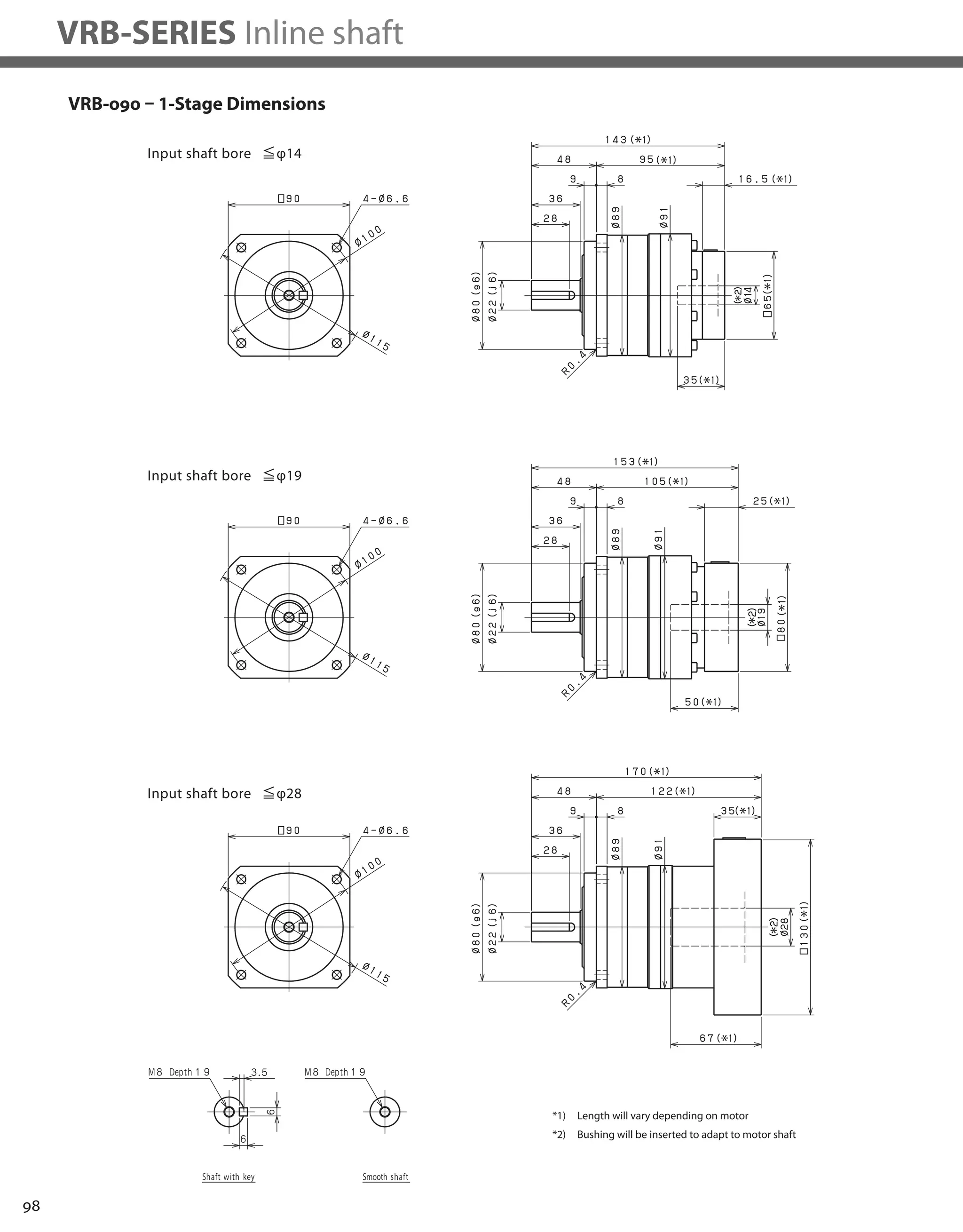
VRB-SERIES Inline shaft
Frame Size 042
Stage 1-Stage
Ratio Units Notes 3 4 5 6 7 8 9 10
Nominal Output Torque [Nm] *1 6 9 9 9 9 9 6 6
Maximum Acceleration Torque [Nm] *2 12 18 18 18 18 18 12 12
Emergency Stop Torque [Nm] *3 30 35 35 35 35 35 30 30
Nominal Input Speed [rpm] *4 4000
Maximum Input Speed [rpm] *5 8000
No Load Running Torque [Nm] *6 0.03
Permitted Radial Load [N] *7 240 270 290 310 320 340 350 360
Permitted Axial Load [N] *8 270 300 330 360 380 410 430 450
Maximum Radial Load [N] *9 710
Maximum Axial Load [N] *10 640
Moment of Inertia (≤Ø 8) [kgcm2] -- 0.053 0.041 0.036 0.034 0.032 0.031 0.031 0.030
Moment of Inertia (≤ Ø 14) [kgcm2] -- 0.091 0.079 0.074 0.072 0.071 0.070 0.069 0.069
Efficiency [%] *11 95
Torsional Rigidity [Nm/arc-min] *12 2
Maximum Torsional Backlash [arc-min] -- ≤ 3
Noise Level [dB] *13 61
Protection Class -- *14 IP54 (IP65)
Ambient Temperature [°C] -- 0-40
Permitted Housing Temperature [°C] -- 90
Weight [kg] *15 0.6
Frame Size 042
Stage 2-Stage
Ratio Units Notes 15 16 20 25 28 30 35 40
Nominal Output Torque [Nm] *1 6 9 9 9 9 6 9 9
Maximum Acceleration Torque [Nm] *2 12 18 18 18 18 12 18 18
Emergency Stop Torque [Nm] *3 30 35 35 35 35 30 35 35
Nominal Input Speed [rpm] *4 4000
Maximum Input Speed [rpm] *5 8000
No Load Running Torque [Nm] *6 0.01
Permitted Radial Load [N] *7 410 420 460 490 510 520 550 570
Permitted Axial Load [N] *8 540 550 610 640 640 640 640 640
Maximum Radial Load [N] *9 710
Maximum Axial Load [N] *10 640
Moment of Inertia (≤Ø 8) [kgcm2] -- 0.035 0.038 0.034 0.034 0.038 0.030 0.034 0.030
Moment of Inertia (≤ Ø 14) [kgcm2] -- -- -- -- -- -- -- -- --
Efficiency [%] *11 90
Torsional Rigidity [Nm/arc-min] *12 2
Maximum Torsional Backlash [arc-min] -- ≤ 5
Noise Level [dB] *13 61
Protection Class -- *14 IP54 (IP65)
Ambient Temperature [°C] -- 0-40
Permitted Housing Temperature [°C] -- 90
Weight [kg] *15 0.7
VRB-042 – 1-Stage Specifications
VRB-042 – 2-Stage Specifications](https://image.slidesharecdn.com/shimpohighprecisioncatalog-140807090507-phpapp01/75/Shimpo-high-precision-catalog-86-2048.jpg)
![85
VRB
Frame Size 042
Stage 2-Stage
Ratio Units Notes 45 50 60 70 80 90 100
Nominal Output Torque [Nm] *1 6 9 9 9 9 6 6
Maximum Acceleration Torque [Nm] *2 12 18 18 18 18 12 12
Emergency Stop Torque [Nm] *3 30 35 35 35 35 30 30
Nominal Input Speed [rpm] *4 4000
Maximum Input Speed [rpm] *5 8000
No Load Running Torque [Nm] *6 0.01
Permitted Radial Load [N] *7 600 620 660 690 710 710 710
Permitted Axial Load [N] *8 640 640 640 640 640 640 640
Maximum Radial Load [N] *9 710
Maximum Axial Load [N] *10 640
Moment of Inertia (≤Ø 8) [kgcm2] -- 0.034 0.030 0.030 0.030 0.030 0.030 0.030
Moment of Inertia (≤ Ø 14) [kgcm2] -- -- -- -- -- -- -- --
Efficiency [%] *11 90
Torsional Rigidity [Nm/arc-min] *12 2
Maximum Torsional Backlash [arc-min] -- ≤ 5
Noise Level [dB] *13 61
Protection Class -- *14 IP54 (IP65)
Ambient Temperature [°C] -- 0-40
Permitted Housing Temperature [°C] -- 90
Weight [kg] *15 0.7
VRB-042 – 2-Stage Specifications
*1) At nominal input speed, service life is 20,000 hours
*2) The maximum torque when starting or stopping operation
*3) The maximum torque allowed under a stress situation (Permitted 1,000 times during service life)
*4) The average input speed
*5) The maximum intermittent input speed
*6) This is the torque at no load applied on the input shaft. The input speed is 4,000 rpm for VRB 042
*7) At this load and nominal input speed, service life will be 20,000 hours. (The radial load applied to the output side bearing)
*8) At this load and nominal input speed, service life will be 20,000 hours. (The axial load applied to the output shaft center)
*9) The maximum radial load that the reducer can accept
*10) The maximum axial load that the reducer can accept
*11) The efficiency at the nominal torque rating
*12) This does not include the lost motion
*13) Contact NIDEC-SHIMPO for the testing conditions and environment
*14) IP65 (wash-down) is available as an option. Contact NIDEC-SHIMPO for more details and our food grade options
*15) The weight may vary slightly between models](https://image.slidesharecdn.com/shimpohighprecisioncatalog-140807090507-phpapp01/75/Shimpo-high-precision-catalog-87-2048.jpg)


![90
VRB-SERIES Inline shaft
VRB-060 – 1-Stage Specifications
VRB-060 – 2-Stage Specifications
Frame Size 060
Stage 1-Stage
Ratio Unit Note 3 4 5 6 7 8 9 10
Nominal Output Torque [Nm] *1 18 27 27 27 27 27 18 18
Maximum Acceleration Torque [Nm] *2 35 50 50 50 50 50 35 35
Emergency Stop Torque [Nm] *3 80 100 100 100 100 100 80 80
Nominal Input Speed [rpm] *4 3000
Maximum Input Speed [rpm] *5 6000
No Load Running Torque [Nm] *6 0.15
Permitted Radial Load [N] *7 430 470 510 540 570 600 620 640
Permitted Axial Load [N] *8 310 360 390 430 460 480 510 530
Maximum Radial Load [N] *9 1200
Maximum Axial Load [N] *10 1100
Moment of Inertia (≤Ø 8) [kgcm2] -- 0.140 0.095 0.077 0.068 0.062 0.059 0.057 0.056
Moment of Inertia (≤ Ø 14) [kgcm2] -- 0.220 0.170 0.160 0.150 0.140 0.140 0.140 0.140
Moment of Inertia (≤ Ø 19) [kgcm2] -- 0.430 0.380 0.360 0.360 0.350 0.350 0.340 0.340
Efficiency [%] *11 95
Torsional Rigidity [Nm/arc-min] *12 3
Maximum Torsional Backlash [arc-min] -- ≤ 3
Noise Level [dB] *13 66
Protection Class -- *14 IP54 (IP65)
Ambient Temperature [°C] -- 0-40
Permitted Housing Temperature [°C] -- 90
Weight [kg] *15 1.4
Frame Size 060
Stage 2-Stage
Ratio Unit Note 15 16 20 25 28 30 35 40
Nominal Output Torque [Nm] *1 18 27 27 27 27 18 27 27
Maximum Acceleration Torque [Nm] *2 35 50 50 50 50 35 50 50
Emergency Stop Torque [Nm] *3 80 100 100 100 100 80 100 100
Nominal Input Speed [rpm] *4 3000
Maximum Input Speed [rpm] *5 6000
No Load Running Torque [Nm] *6 0.04
Permitted Radial Load [N] *7 740 750 810 870 910 930 980 1000
Permitted Axial Load [N] *8 630 650 720 790 830 860 920 970
Maximum Radial Load [N] *9 1200
Maximum Axial Load [N] *10 1100
Moment of Inertia (≤Ø 8) [kgcm2] -- 0.055 0.057 0.054 0.053 0.055 0.049 0.053 0.049
Moment of Inertia (≤ Ø 14) [kgcm2] -- 0.140 0.140 0.130 0.130 0.140 0.130 0.130 0.130
Moment of Inertia (≤ Ø 19) [kgcm2] -- -- -- -- -- -- -- -- --
Efficiency [%] *11 90
Torsional Rigidity [Nm/arc-min] *12 3
Maximum Torsional Backlash [arc-min] -- ≤ 3
Noise Level [dB] *13 66
Protection Class -- *14 IP54 (IP65)
Ambient Temperature [°C] -- 0-40
Permitted Housing Temperature [°C] -- 90
Weight [kg] *15 1.6](https://image.slidesharecdn.com/shimpohighprecisioncatalog-140807090507-phpapp01/75/Shimpo-high-precision-catalog-92-2048.jpg)
![91
VRB
VRB-060 – 2-Stage Specifications
Frame Size 060
Stage 2-Stage
Ratio Unit Note 45 50 60 70 80 90 100
Nominal Output Torque [Nm] *1 18 27 27 27 27 18 18
Maximum Acceleration Torque [Nm] *2 35 50 50 50 50 35 35
Emergency Stop Torque [Nm] *3 80 100 100 100 100 80 80
Nominal Input Speed [rpm] *4 3000
Maximum Input Speed [rpm] *5 6000
No Load Running Torque [Nm] *6 0.04
Permitted Radial Load [N] *7 1100 1100 1200 1200 1200 1200 1200
Permitted Axial Load [N] *8 1000 1100 1100 1100 1100 1100 1100
Maximum Radial Load [N] *9 1200
Maximum Axial Load [N] *10 1100
Moment of Inertia (≤Ø 8) [kgcm2] -- 0.053 0.049 0.049 0.049 0.049 0.049 0.049
Moment of Inertia (≤ Ø 14) [kgcm2] -- 0.130 0.130 0.130 0.130 0.130 0.130 0.130
Moment of Inertia (≤ Ø 19) [kgcm2] -- -- -- -- -- -- -- --
Efficiency [%] *11 90
Torsional Rigidity [Nm/arc-min] *12 3
Maximum Torsional Backlash [arc-min] -- ≤ 3
Noise Level [dB] *13 66
Protection Class -- *14 IP54 (IP65)
Ambient Temperature [°C] -- 0-40
Permitted Housing Temperature [°C] -- 90
Weight [kg] *15 1.6
*1) At nominal input speed, service life is 20,000 hours
*2) The maximum torque when starting or stopping operation
*3) The maximum torque allowed under a stress situation (Permitted 1,000 times during service life)
*4) The average input speed
*5) The maximum intermittent input speed
*6) This is the torque at no load applied on the input shaft. The input speed is 3,000 rpm for VRB 060
*7) At this load and nominal input speed, service life will be 20,000 hours. (The radial load applied to the output side bearing)
*8) At this load and nominal input speed, service life will be 20,000 hours. (The axial load applied to the output shaft center)
*9) The maximum radial load that the reducer can accept
*10) The maximum axial load that the reducer can accept
*11) The efficiency at the nominal torque rating
*12) This does not include the lost motion
*13) Contact NIDEC-SHIMPO for the testing conditions and environment
*14) IP65 (wash-down) is available as an option. Contact NIDEC-SHIMPO for more details and our food grade options
*15) The weight may vary slightly between models](https://image.slidesharecdn.com/shimpohighprecisioncatalog-140807090507-phpapp01/75/Shimpo-high-precision-catalog-93-2048.jpg)


![96
VRB-SERIES Inline shaft
VRB-090 – 1-Stage Specifications
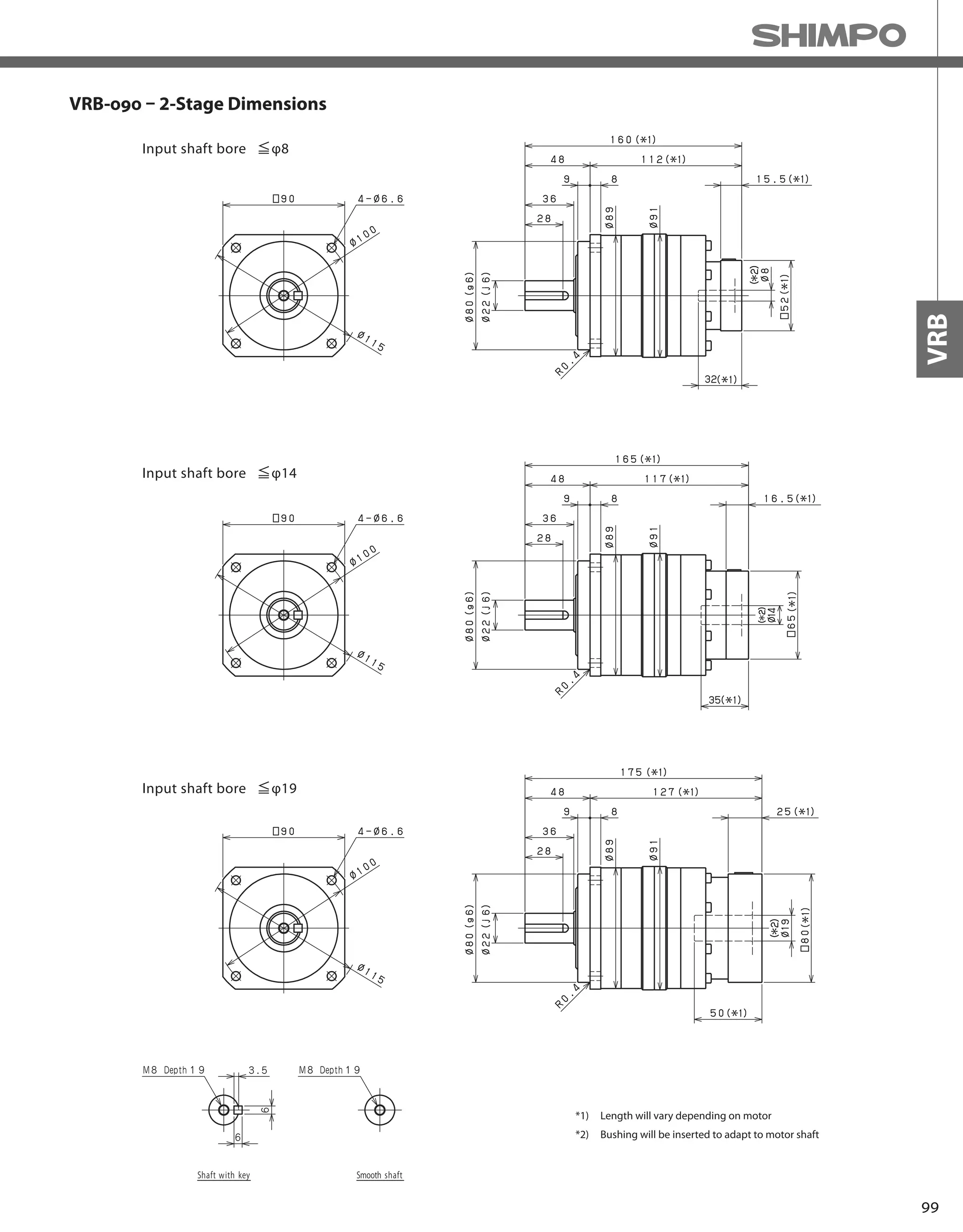
VRB-090 – 2-Stage Specifications
Frame Size 090
Stage 1-Stage
Ratio Unit Note 3 4 5 6 7 8 9 10
Nominal Output Torque [Nm] *1 50 75 75 75 75 75 50 50
Maximum Acceleration Torque [Nm] *2 80 125 125 125 125 125 80 80
Emergency Stop Torque [Nm] *3 200 250 250 250 250 250 200 200
Nominal Input Speed [rpm] *4 3000
Maximum Input Speed [rpm] *5 6000
No Load Running Torque [Nm] *6 0.35
Permitted Radial Load [N] *7 810 890 960 1000 1100 1100 1200 1200
Permitted Axial Load [N] *8 930 1100 1200 1300 1300 1400 1500 1600
Maximum Radial Load [N] *9 2400
Maximum Axial Load [N] *10 2200
Moment of Inertia (≤Ø 8) [kgcm2] -- -- -- -- -- -- -- -- --
Moment of Inertia (≤ Ø 14) [kgcm2] -- 0.720 0.490 0.400 0.360 0.320 0.310 0.290 0.290
Moment of Inertia (≤ Ø 19) [kgcm2] -- 1.200 0.950 0.860 0.820 0.790 0.770 0.760 0.750
Moment of Inertia (≤ Ø 28) [kgcm2] -- 3.200 3.000 2.900 2.800 2.800 2.800 2.800 2.800
Efficiency [%] *11 95
Torsional Rigidity [Nm/arc-min] *12 10
Maximum Torsional Backlash [arc-min] -- ≤ 3
Noise Level [dB] *13 67
Protection Class -- *14 IP54 (IP65)
Ambient Temperature [°C] -- 0-40
Permitted Housing Temperature [°C] -- 90
Weight [kg] *15 3.7
Frame Size 090
Stage 2-Stage
Ratio Unit Note 15 16 20 25 28 30 35 40
Nominal Output Torque [Nm] *1 50 75 75 75 75 50 75 75
Maximum Acceleration Torque [Nm] *2 80 125 125 125 125 80 125 125
Emergency Stop Torque [Nm] *3 200 250 250 250 250 200 250 250
Nominal Input Speed [rpm] *4 3000
Maximum Input Speed [rpm] *5 6000
No Load Running Torque [Nm] *6 0.06
Permitted Radial Load [N] *7 1400 1400 1500 1600 1700 1700 1800 1900
Permitted Axial Load [N] *8 1900 1900 2100 2200 2200 2200 2200 2200
Maximum Radial Load [N] *9 2400
Maximum Axial Load [N] *10 2200
Moment of Inertia (≤Ø 8) [kgcm2] -- 0.130 0.150 0.130 0.120 0.140 0.100 0.120 0.099
Moment of Inertia (≤ Ø 14) [kgcm2] -- 0.280 0.300 0.280 0.280 0.290 0.250 0.270 0.250
Moment of Inertia (≤ Ø 19) [kgcm2] -- 0.720 0.740 0.720 0.710 0.730 0.700 0.710 0.700
Moment of Inertia (≤ Ø 28) [kgcm2] -- -- -- -- -- -- -- -- --
Efficiency [%] *11 90
Torsional Rigidity [Nm/arc-min] *12 10
Maximum Torsional Backlash [arc-min] -- ≤ 3
Noise Level [dB] *13 67
Protection Class -- *14 IP54 (IP65)
Ambient Temperature [°C] -- 0-40
Permitted Housing Temperature [°C] -- 90
Weight [kg] *15 4.2](https://image.slidesharecdn.com/shimpohighprecisioncatalog-140807090507-phpapp01/75/Shimpo-high-precision-catalog-98-2048.jpg)
![97
VRB
VRB-090 – 2-Stage Specifications
Frame Size 090
Stage 2-Stage
Ratio Unit Note 45 50 60 70 80 90 100
Nominal Output Torque [Nm] *1 50 75 75 75 75 50 50
Maximum Acceleration Torque [Nm] *2 80 125 125 125 125 80 80
Emergency Stop Torque [Nm] *3 200 250 250 250 250 200 200
Nominal Input Speed [rpm] *4 3000
Maximum Input Speed [rpm] *5 6000
No Load Running Torque [Nm] *6 0.06
Permitted Radial Load [N] *7 2000 2100 2200 2300 2400 2400 2400
Permitted Axial Load [N] *8 2200 2200 2200 2200 2200 2200 2200
Maximum Radial Load [N] *9 2400
Maximum Axial Load [N] *10 2200
Moment of Inertia (≤Ø 8) [kgcm2] -- 0.120 0.098 0.098 0.097 0.097 0.097 0.097
Moment of Inertia (≤ Ø 14) [kgcm2] -- 0.270 0.250 0.250 0.250 0.250 0.250 0.250
Moment of Inertia (≤ Ø 19) [kgcm2] -- 0.710 0.690 0.690 0.690 0.690 0.690 0.690
Moment of Inertia (≤ Ø 28) [kgcm2] -- -- -- -- -- -- -- --
Efficiency [%] *11 90
Torsional Rigidity [Nm/arc-min] *12 10
Maximum Torsional Backlash [arc-min] -- ≤ 3
Noise Level [dB] *13 67
Protection Class -- *14 IP54 (IP65)
Ambient Temperature [°C] -- 0-40
Permitted Housing Temperature [°C] -- 90
Weight [kg] *15 4.2
*1) At nominal input speed, service life is 20,000 hours
*2) The maximum torque when starting or stopping operation
*3) The maximum torque allowed under a stress situation (Permitted 1,000 times during service life)
*4) The average input speed
*5) The maximum intermittent input speed
*6) This is the torque at no load applied on the input shaft. The input speed is 3,000 rpm for VRB 090
*7) At this load and nominal input speed, service life will be 20,000 hours. (The radial load applied to the output side bearing)
*8) At this load and nominal input speed, service life will be 20,000 hours. (The axial load applied to the output shaft center)
*9) The maximum radial load that the reducer can accept
*10) The maximum axial load that the reducer can accept
*11) The efficiency at the nominal torque rating
*12) This does not include the lost motion
*13) Contact NIDEC-SHIMPO for the testing conditions and environment
*14) IP65 (wash-down) is available as an option. Contact NIDEC-SHIMPO for more details and our food grade options
*15) The weight may vary slightly between models](https://image.slidesharecdn.com/shimpohighprecisioncatalog-140807090507-phpapp01/75/Shimpo-high-precision-catalog-99-2048.jpg)

![102
VRB-SERIES Inline shaft
VRB-115 – 1-Stage Specifications
VRB-115 – 2-Stage Specifications
Frame Size 115
Stage 1-Stage
Ratio Unit Note 3 4 5 6 7 8 9 10
Nominal Output Torque [Nm] *1 120 120 180 180 180 180 120 120
Maximum Acceleration Torque [Nm] *2 225 330 330 330 330 330 225 225
Emergency Stop Torque [Nm] *3 500 625 625 625 625 625 500 500
Nominal Input Speed [rpm] *4 3000
Maximum Input Speed [rpm] *5 6000
No Load Running Torque [Nm] *6 1.30
Permitted Radial Load [N] *7 1300 1500 1600 1700 1800 1900 1900 2000
Permitted Axial Load [N] *8 1500 1700 1900 2000 2100 2300 2400 2500
Maximum Radial Load [N] *9 4300
Maximum Axial Load [N] *10 3900
Moment of Inertia (≤Ø 14) [kgcm2] -- -- -- -- -- -- -- -- --
Moment of Inertia (≤ Ø 19) [kgcm2] -- 3.300 2.000 1.600 1.300 1.100 1.000 0.980 0.950
Moment of Inertia (≤ Ø 28) [kgcm2] -- 5.300 4.100 3.600 3.300 3.200 3.100 3.000 3.000
Moment of Inertia (≤ Ø 38) [kgcm2] -- 13.000 12.000 11.000 11.000 11.000 11.000 11.000 11.000
Efficiency [%] *11 95
Torsional Rigidity [Nm/arc-min] *12 31
Maximum Torsional Backlash [arc-min] -- ≤ 3
Noise Level [dB] *13 71
Protection Class -- *14 IP54 (IP65)
Ambient Temperature [°C] -- 0-40
Permitted Housing Temperature [°C] -- 90
Weight [kg] *15 8
Frame Size 115
Stage 2-Stage
Ratio Unit Note 15 16 20 25 28 30 35 40
Nominal Output Torque [Nm] *1 120 180 180 180 180 120 180 180
Maximum Acceleration Torque [Nm] *2 225 330 330 330 330 225 330 330
Emergency Stop Torque [Nm] *3 500 625 625 625 625 500 625 625
Nominal Input Speed [rpm] *4 3000
Maximum Input Speed [rpm] *5 6000
No Load Running Torque [Nm] *6 0.42
Permitted Radial Load [N] *7 2300 2300 2500 2700 2800 2900 3000 3200
Permitted Axial Load [N] *8 3000 3100 3400 3700 3900 3900 3900 3900
Maximum Radial Load [N] *9 4300
Maximum Axial Load [N] *10 3900
Moment of Inertia (≤Ø 14) [kgcm2] -- 0.430 0.480 0.400 0.380 0.440 0.290 0.370 0.280
Moment of Inertia (≤ Ø 19) [kgcm2] -- 0.860 0.920 0.830 0.820 0.880 0.740 0.810 0.730
Moment of Inertia (≤ Ø 28) [kgcm2] -- 2.800 2.900 2.800 2.800 2.800 2.700 2.700 2.700
Moment of Inertia (≤ Ø 38) [kgcm2] -- -- -- -- -- -- -- -- --
Efficiency [%] *11 90
Torsional Rigidity [Nm/arc-min] *12 31
Maximum Torsional Backlash [arc-min] -- ≤ 3
Noise Level [dB] *13 71
Protection Class -- *14 IP54 (IP65)
Ambient Temperature [°C] -- 0-40
Permitted Housing Temperature [°C] -- 90
Weight [kg] *15 8.9](https://image.slidesharecdn.com/shimpohighprecisioncatalog-140807090507-phpapp01/75/Shimpo-high-precision-catalog-104-2048.jpg)
![103
VRB
VRB-115 – 2-Stage Specifications
Frame Size 115
Stage 2-Stage
Ratio Unit Note 45 50 60 70 80 90 100
Nominal Output Torque [Nm] *1 120 180 180 180 180 120 120
Maximum Acceleration Torque [Nm] *2 225 330 330 330 330 225 225
Emergency Stop Torque [Nm] *3 500 625 625 625 625 500 500
Nominal Input Speed [rpm] *4 3000
Maximum Input Speed [rpm] *5 6000
No Load Running Torque [Nm] *6 0.42
Permitted Radial Load [N] *7 3300 3400 3600 3800 4000 4200 4300
Permitted Axial Load [N] *8 3900 3900 3900 3900 3900 3900 3900
Maximum Radial Load [N] *9 4300
Maximum Axial Load [N] *10 3900
Moment of Inertia (≤Ø 14) [kgcm2] -- 0.370 0.280 0.280 0.280 0.280 0.270 0.270
Moment of Inertia (≤ Ø 19) [kgcm2] -- 0.800 0.730 0.730 0.730 0.730 0.730 0.730
Moment of Inertia (≤ Ø 28) [kgcm2] -- 2.700 2.700 2.700 2.700 2.700 2.700 2.700
Moment of Inertia (≤ Ø 38) [kgcm2] -- -- -- -- -- -- -- --
Efficiency [%] *11 90
Torsional Rigidity [Nm/arc-min] *12 31
Maximum Torsional Backlash [arc-min] -- ≤ 3
Noise Level [dB] *13 71
Protection Class -- *14 IP54 (IP65)
Ambient Temperature [°C] -- 0-40
Permitted Housing Temperature [°C] -- 90
Weight [kg] *15 8.9
*1) At nominal input speed, service life is 20,000 hours
*2) The maximum torque when starting or stopping operation
*3) The maximum torque allowed under a stress situation (Permitted 1,000 times during service life)
*4) The average input speed
*5) The maximum intermittent input speed
*6) This is the torque at no load applied on the input shaft. The input speed is 3,000 rpm for VRB 115
*7) At this load and nominal input speed, service life will be 20,000 hours. (The radial load applied to the output side bearing)
*8) At this load and nominal input speed, service life will be 20,000 hours. (The axial load applied to the output shaft center)
*9) The maximum radial load that the reducer can accept
*10) The maximum axial load that the reducer can accept
*11) The efficiency at the nominal torque rating
*12) This does not include the lost motion
*13) Contact NIDEC-SHIMPO for the testing conditions and environment
*14) IP65 (wash-down) is available as an option. Contact NIDEC-SHIMPO for more details and our food grade options
*15) The weight may vary slightly between models](https://image.slidesharecdn.com/shimpohighprecisioncatalog-140807090507-phpapp01/75/Shimpo-high-precision-catalog-105-2048.jpg)


![108
VRB-SERIES Inline shaft
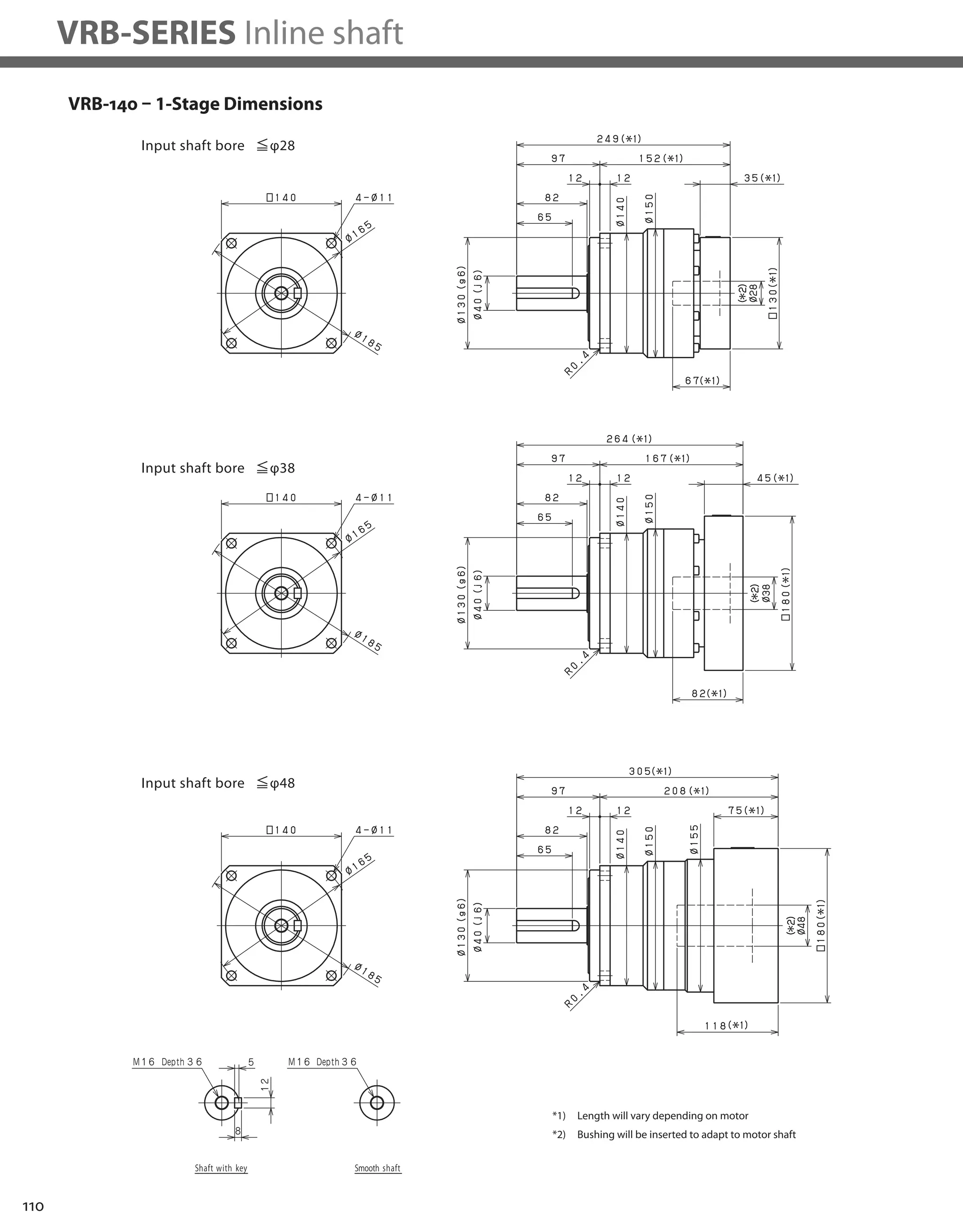
VRB-140 – 1-Stage Specifications
VRB-140 – 2-Stage Specifications
Frame Size 140
Stage 1-Stage
Ratio Unit Note 3 4 5 6 7 8 9 10
Nominal Output Torque [Nm] *1 240 240 360 360 360 360 240 240
Maximum Acceleration Torque [Nm] *2 470 700 700 700 700 700 470 470
Emergency Stop Torque [Nm] *3 1000 1250 1250 1250 1250 1250 1000 1000
Nominal Input Speed [rpm] *4 2000
Maximum Input Speed [rpm] *5 4000
No Load Running Torque [Nm] *6 1.63
Permitted Radial Load [N] *7 3200 3500 3800 4000 4200 4400 4600 4700
Permitted Axial Load [N] *8 2400 2700 3000 3300 3500 3700 3900 4100
Maximum Radial Load [N] *9 9100
Maximum Axial Load [N] *10 8200
Moment of Inertia (≤Ø 19) [kgcm2] -- -- -- -- -- -- -- -- --
Moment of Inertia (≤ Ø 28) [kgcm2] -- 12.000 7.500 5.800 4.900 4.100 3.800 3.600 3.500
Moment of Inertia (≤ Ø 38) [kgcm2] -- 20.000 15.000 14.000 13.000 12.000 12.000 11.000 11.000
Moment of Inertia (≤ Ø 48) [kgcm2] -- 42.000 37.000 36.000 35.000 34.000 34.000 34.000 34.000
Efficiency [%] *11 95
Torsional Rigidity [Nm/arc-min] *12 60
Maximum Torsional Backlash [arc-min] -- ≤ 3
Noise Level [dB] *13 67
Protection Class -- *14 IP54 (IP65)
Ambient Temperature [°C] -- 0-40
Permitted Housing Temperature [°C] -- 90
Weight [kg] *15 16
Frame Size 140
Stage 2-Stage
Ratio Unit Note 15 16 20 25 28 30 35 40
Nominal Output Torque [Nm] *1 240 360 360 360 360 240 360 360
Maximum Acceleration Torque [Nm] *2 470 700 700 700 700 470 700 700
Emergency Stop Torque [Nm] *3 1000 1250 1250 1250 1250 1000 1250 1250
Nominal Input Speed [rpm] *4 2000
Maximum Input Speed [rpm] *5 4000
No Load Running Torque [Nm] *6 0.56
Permitted Radial Load [N] *7 5400 5500 6000 6400 6700 6800 7200 7500
Permitted Axial Load [N] *8 4900 5000 5500 6100 6400 6600 7000 7500
Maximum Radial Load [N] *9 9100
Maximum Axial Load [N] *10 8200
Moment of Inertia (≤Ø 19) [kgcm2] -- 1.300 1.500 1.200 1.100 1.400 0.850 1.100 0.830
Moment of Inertia (≤ Ø 28) [kgcm2] -- 3.200 3.500 3.100 3.100 3.300 2.800 3.100 2.800
Moment of Inertia (≤ Ø 38) [kgcm2] -- 11.000 11.000 11.000 11.000 11.000 10.000 11.000 10.000
Moment of Inertia (≤ Ø 48) [kgcm2] -- -- -- -- -- -- -- -- --
Efficiency [%] *11 90
Torsional Rigidity [Nm/arc-min] *12 60
Maximum Torsional Backlash [arc-min] -- ≤ 3
Noise Level [dB] *13 67
Protection Class -- *14 IP54 (IP65)
Ambient Temperature [°C] -- 0-40
Permitted Housing Temperature [°C] -- 90
Weight [kg] *15 17](https://image.slidesharecdn.com/shimpohighprecisioncatalog-140807090507-phpapp01/75/Shimpo-high-precision-catalog-110-2048.jpg)
![109
VRB
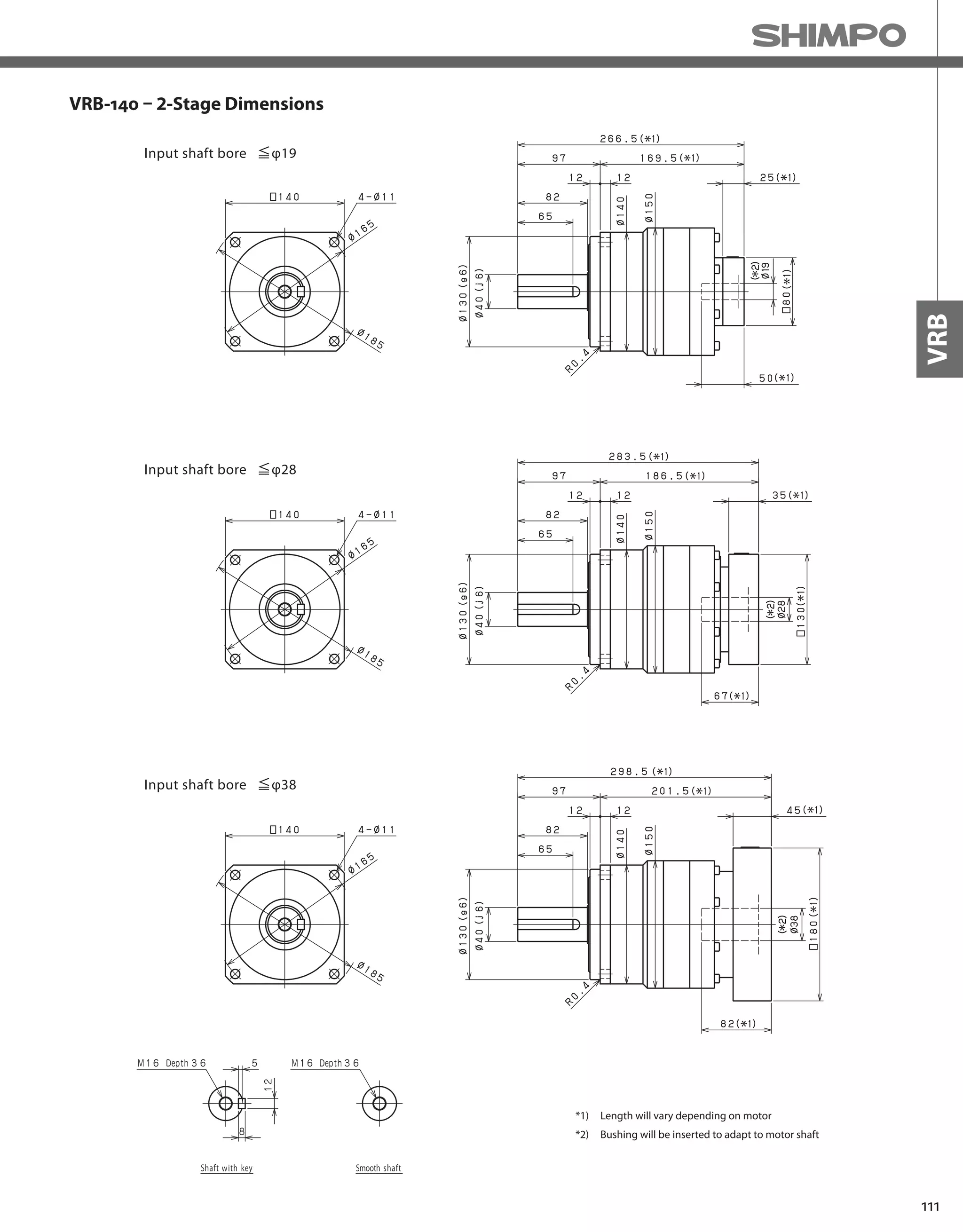
VRB-140 – 2-Stage Specifications
Frame Size 140
Stage 2-Stage
Ratio Unit Note 45 50 60 70 80 90 100
Nominal Output Torque [Nm] *1 240 360 360 360 360 240 240
Maximum Acceleration Torque [Nm] *2 470 700 700 700 700 470 470
Emergency Stop Torque [Nm] *3 1000 1250 1250 1250 1250 1000 1000
Nominal Input Speed [rpm] *4 2000
Maximum Input Speed [rpm] *5 4000
No Load Running Torque [Nm] *6 0.56
Permitted Radial Load [N] *7 7800 8100 8600 9100 9100 9100 9100
Permitted Axial Load [N] *8 7900 8200 8200 8200 8200 8200 8200
Maximum Radial Load [N] *9 9100
Maximum Axial Load [N] *10 8200
Moment of Inertia (≤Ø 19) [kgcm2] -- 1.100 0.810 0.810 0.800 0.800 0.800 0.800
Moment of Inertia (≤ Ø 28) [kgcm2] -- 3.000 2.800 2.800 2.800 2.800 2.800 2.800
Moment of Inertia (≤ Ø 38) [kgcm2] -- 11.000 10.000 10.000 10.000 10.000 10.000 10.000
Moment of Inertia (≤ Ø 48) [kgcm2] -- -- -- -- -- -- -- --
Efficiency [%] *11 90
Torsional Rigidity [Nm/arc-min] *12 60
Maximum Torsional Backlash [arc-min] -- ≤ 3
Noise Level [dB] *13 67
Protection Class -- *14 IP54 (IP65)
Ambient Temperature [°C] -- 0-40
Permitted Housing Temperature [°C] -- 90
Weight [kg] *15 17
*1) At nominal input speed, service life is 20,000 hours
*2) The maximum torque when starting or stopping operation
*3) The maximum torque allowed under a stress situation (Permitted 1,000 times during service life)
*4) The average input speed
*5) The maximum intermittent input speed
*6) This is the torque at no load applied on the input shaft. The input speed is 2,000 rpm for VRB140
*7) At this load and nominal input speed, service life will be 20,000 hours. (The radial load applied to the output side bearing)
*8) At this load and nominal input speed, service life will be 20,000 hours. (The axial load applied to the output shaft center)
*9) The maximum radial load that the reducer can accept
*10) The maximum axial load that the reducer can accept
*11) The efficiency at the nominal torque rating
*12) This does not include the lost motion
*13) Contact NIDEC-SHIMPO for the testing conditions and environment
*14) IP65 (wash-down) is available as an option. Contact NIDEC-SHIMPO for more details and our food grade options
*15) The weight may vary slightly between models](https://image.slidesharecdn.com/shimpohighprecisioncatalog-140807090507-phpapp01/75/Shimpo-high-precision-catalog-111-2048.jpg)


![114
VRB-SERIES Inline shaft
VRB-180 – 1-Stage Specifications
Frame Size 180
Stage 1-Stage
Ratio Unit Note 3 4 5 6 7 8 9 10
Nominal Output Torque [Nm] *1 500 750 750 750 750 750 500 500
Maximum Acceleration Torque [Nm] *2 970 1400 1400 1400 1400 1400 970 970
Emergency Stop Torque [Nm] *3 2200 2750 2750 2750 2750 2750 2200 2200
Nominal Input Speed [rpm] *4 1500
Maximum Input Speed [rpm] *5 3000
No Load Running Torque [Nm] *6 2.68
Permitted Radial Load [N] *7 5600 6200 6700 7100 7400 7800 8100 8400
Permitted Axial Load [N] *8 4300 4900 5400 5800 6300 6600 7000 7300
Maximum Radial Load [N] *9 15000
Maximum Axial Load [N] *10 14000
Moment of Inertia (≤Ø 28) [kgcm2] -- -- -- -- -- -- -- -- --
Moment of Inertia (≤ Ø 38) [kgcm2] -- 44.000 28.000 22.000 18.000 16.000 15.000 14.000 14.000
Moment of Inertia (≤ Ø 48) [kgcm2] -- 66.000 50.000 44.000 41.000 38.000 37.000 36.000 36.000
Moment of Inertia (≤ Ø 65) [kgcm2] -- 130.000 110.000 100.000 100.000 99.000 97.000 97.000 96.000
Efficiency [%] *11 95
Torsional Rigidity [Nm/arc-min] *12 175
Maximum Torsional Backlash [arc-min] -- ≤ 3
Noise Level [dB] *13 67
Protection Class -- *14 IP54 (IP65)
Ambient Temperature [°C] -- 0-40
Permitted Housing Temperature [°C] -- 90
Weight [kg] *15 36
Frame Size 180
Stage 2-Stage
Ratio Unit Note 15 16 20 25 28 30 35 40
Nominal Output Torque [Nm] *1 500 750 750 750 750 500 750 750
Maximum Acceleration Torque [Nm] *2 970 1400 1400 1400 1400 970 1400 1400
Emergency Stop Torque [Nm] *3 2200 2750 2750 2750 2750 2200 2750 2750
Nominal Input Speed [rpm] *4 1500
Maximum Input Speed [rpm] *5 3000
No Load Running Torque [Nm] *6 1.39
Permitted Radial Load [N] *7 9600 9800 11000 11000 12000 12000 13000 13000
Permitted Axial Load [N] *8 8700 8900 9900 11000 11000 12000 13000 13000
Maximum Radial Load [N] *9 15000
Maximum Axial Load [N] *10 14000
Moment of Inertia (≤Ø 28) [kgcm2] -- 4.700 5.400 4.400 4.200 4.900 3.200 4.100 3.200
Moment of Inertia (≤ Ø 38) [kgcm2] -- 12.000 13.000 12.000 12.000 13.000 11.000 12.000 11.000
Moment of Inertia (≤ Ø 48) [kgcm2] -- 34.000 35.000 34.000 34.000 35.000 33.000 34.000 33.000
Moment of Inertia (≤ Ø 65) [kgcm2] -- -- -- -- -- -- -- -- --
Efficiency [%] *11 90
Torsional Rigidity [Nm/arc-min] *12 175
Maximum Torsional Backlash [arc-min] -- ≤ 3
Noise Level [dB] *13 67
Protection Class -- *14 IP54 (IP65)
Ambient Temperature [°C] -- 0-40
Permitted Housing Temperature [°C] -- 90
Weight [kg] *15 37
VRB-180 – 2-Stage Specifications](https://image.slidesharecdn.com/shimpohighprecisioncatalog-140807090507-phpapp01/75/Shimpo-high-precision-catalog-116-2048.jpg)
![115
VRB
VRB-180 – 2-Stage Specifications
Frame Size 180
Stage 2-Stage
Ratio Unit Note 45 50 60 70 80 90 100
Nominal Output Torque [Nm] *1 500 750 750 750 750 500 500
Maximum Acceleration Torque [Nm] *2 970 1400 1400 1400 1400 970 970
Emergency Stop Torque [Nm] *3 2200 2750 2750 2750 2750 2200 2200
Nominal Input Speed [rpm] *4 1500
Maximum Input Speed [rpm] *5 3000
No Load Running Torque [Nm] *6 1.39
Permitted Radial Load [N] *7 14000 14000 15000 15000 15000 15000 15000
Permitted Axial Load [N] *8 14000 14000 14000 14000 14000 14000 14000
Maximum Radial Load [N] *9 15000
Maximum Axial Load [N] *10 14000
Moment of Inertia (≤Ø 28) [kgcm2] -- 4.000 3.100 3.100 3.100 3.100 3.100 3.100
Moment of Inertia (≤ Ø 38) [kgcm2] -- 12.000 11.000 11.000 11.000 11.000 11.000 11.000
Moment of Inertia (≤ Ø 48) [kgcm2] -- 34.000 33.000 33.000 33.000 33.000 33.000 33.000
Moment of Inertia (≤ Ø 65) [kgcm2] -- -- -- -- -- -- -- --
Efficiency [%] *11 90
Torsional Rigidity [Nm/arc-min] *12 175
Maximum Torsional Backlash [arc-min] -- ≤ 3
Noise Level [dB] *13 67
Protection Class -- *14 IP54 (IP65)
Ambient Temperature [°C] -- 0-40
Permitted Housing Temperature [°C] -- 90
Weight [kg] *15 37
*1) At nominal input speed, service life is 20,000 hours
*2) The maximum torque when starting or stopping operation
*3) The maximum torque allowed under a stress situation (Permitted 1,000 times during service life)
*4) The average input speed
*5) The maximum intermittent input speed
*6) This is the torque at no load applied on the input shaft. The input speed is 1,500 rpm for VRB180
*7) At this load and nominal input speed, service life will be 20,000 hours. (The radial load applied to the output side bearing)
*8) At this load and nominal input speed, service life will be 20,000 hours. (The axial load applied to the output shaft center)
*9) The maximum radial load that the reducer can accept
*10) The maximum axial load that the reducer can accept
*11) The efficiency at the nominal torque rating
*12) This does not include the lost motion
*13) Contact NIDEC-SHIMPO for the testing conditions and environment
*14) IP65 (wash-down) is available as an option. Contact NIDEC-SHIMPO for more details and our food grade options
*15) The weight may vary slightly between models](https://image.slidesharecdn.com/shimpohighprecisioncatalog-140807090507-phpapp01/75/Shimpo-high-precision-catalog-117-2048.jpg)


![120
VRB-SERIES Inline shaft
VRB-220 – 1-Stage Specifications
VRB-220 – 2-Stage Specifications
Frame Size 220
Stage 1-Stage
Ratio Unit Note 3 4 5 6 7 8 9 10
Nominal Output Torque [Nm] *1 1000 1500 1500 1500 1500 1500 1000 1000
Maximum Acceleration Torque [Nm] *2 1600 2300 2300 2300 2300 2200 1900 1600
Emergency Stop Torque [Nm] *3 4000 5000 5000 5000 5000 5000 4000 4000
Nominal Input Speed [rpm] *4 1000
Maximum Input Speed [rpm] *5 2000
No Load Running Torque [Nm] *6 2.92
Permitted Radial Load [N] *7 5800 6400 6900 7300 7700 8000 8400 8700
Permitted Axial Load [N] *8 6400 7200 7900 8600 9200 9700 10000 11000
Maximum Radial Load [N] *9 15000
Maximum Axial Load [N] *10 14000
Moment of Inertia (≤ Ø 38) [kgcm2] -- -- -- -- -- -- -- -- --
Moment of Inertia (≤ Ø 48) [kgcm2] -- 90.000 62.000 52.000 47.000 42.000 40.000 39.000 38.000
Moment of Inertia (≤ Ø 65) [kgcm2] -- 150.000 120.000 110.000 110.000 100.000 100.000 99.000 98.000
Efficiency [%] *11 97
Torsional Rigidity [Nm/arc-min] *12 400
Maximum Torsional Backlash [arc-min] -- ≤ 3
Noise Level [dB] *13 61
Protection Class -- *14 IP54 (IP65)
Ambient Temperature [°C] -- 0-40
Permitted Housing Temperature [°C] -- 90
Weight [kg] *15 53
Frame Size 220
Stage 2-Stage
Ratio Unit Note 15 16 20 25 28 30 35 40
Nominal Output Torque [Nm] *1 1000 1500 1500 1500 1500 1000 1500 1500
Maximum Acceleration Torque [Nm] *2 1600 2300 2300 2300 2300 1600 2300 2300
Emergency Stop Torque [Nm] *3 4000 5000 5000 5000 5000 4000 5000 5000
Nominal Input Speed [rpm] *4 1000
Maximum Input Speed [rpm] *5 2000
No Load Running Torque [Nm] *6 1.14
Permitted Radial Load [N] *7 9900 10000 11000 12000 12000 13000 13000 14000
Permitted Axial Load [N] *8 13000 13000 14000 14000 14000 14000 14000 14000
Maximum Radial Load [N] *9 15000
Maximum Axial Load [N] *10 14000
Moment of Inertia (≤ Ø 38) [kgcm2] -- 14.000 16.000 14.000 14.000 15.000 12.000 13.000 12.000
Moment of Inertia (≤ Ø 48) [kgcm2] -- 36.000 37.000 35.000 35.000 36.000 34.000 35.000 33.000
Moment of Inertia (≤ Ø 65) [kgcm2] -- -- -- -- -- -- -- -- --
Efficiency [%] *11 92
Torsional Rigidity [Nm/arc-min] *12 400
Maximum Torsional Backlash [arc-min] -- ≤ 3
Noise Level [dB] *13 61
Protection Class -- *14 IP54 (IP65)
Ambient Temperature [°C] -- 0-40
Permitted Housing Temperature [°C] -- 90
Weight [kg] *15 54](https://image.slidesharecdn.com/shimpohighprecisioncatalog-140807090507-phpapp01/75/Shimpo-high-precision-catalog-122-2048.jpg)
![121
VRB
VRB-220 – 2-Stage Specifications
Frame Size 220
Stage 2-Stage
Ratio Unit Note 45 50 60 70 80 90 100
Nominal Output Torque [Nm] *1 1000 1500 1500 1500 1500 1000 1000
Maximum Acceleration Torque [Nm] *2 1300 2300 2300 2300 1800 1300 1200
Emergency Stop Torque [Nm] *3 4000 5000 5000 5000 5000 4000 4000
Nominal Input Speed [rpm] *4 1000
Maximum Input Speed [rpm] *5 2000
No Load Running Torque [Nm] *6 1.14
Permitted Radial Load [N] *7 14000 15000 15000 15000 15000 15000 15000
Permitted Axial Load [N] *8 14000 14000 14000 14000 14000 14000 14000
Maximum Radial Load [N] *9 15000
Maximum Axial Load [N] *10 14000
Moment of Inertia (≤ Ø 38) [kgcm2] -- 13.000 12.000 12.000 12.000 12.000 12.000 12.000
Moment of Inertia (≤ Ø 48) [kgcm2] -- 35.000 33.000 33.000 33.000 33.000 33.000 33.000
Moment of Inertia (≤ Ø 65) [kgcm2] -- -- -- -- -- -- -- --
Efficiency [%] *11 92
Torsional Rigidity [Nm/arc-min] *12 400
Maximum Torsional Backlash [arc-min] -- ≤ 3
Noise Level [dB] *13 61
Protection Class -- *14 IP54 (IP65)
Ambient Temperature [°C] -- 0-40
Permitted Housing Temperature [°C] -- 90
Weight [kg] *15 54
*1) At nominal input speed, service life is 20,000 hours
*2) The maximum torque when starting or stopping operation
*3) The maximum torque allowed under a stress situation (Permitted 1,000 times during service life)
*4) The average input speed
*5) The maximum intermittent input speed
*6) This is the torque at no load applied on the input shaft. The input speed is 1,000 rpm for VRB220
*7) At this load and nominal input speed, service life will be 20,000 hours. (The radial load applied to the output side bearing)
*8) At this load and nominal input speed, service life will be 20,000 hours. (The axial load applied to the output shaft center)
*9) The maximum radial load that the reducer can accept
*10) The maximum axial load that the reducer can accept
*11) The efficiency at the nominal torque rating
*12) This does not include the lost motion
*13) Contact NIDEC-SHIMPO for the testing conditions and environment
*14) IP65 (wash-down) is available as an option. Contact NIDEC-SHIMPO for more details and our food grade options
*15) The weight may vary slightly between models](https://image.slidesharecdn.com/shimpohighprecisioncatalog-140807090507-phpapp01/75/Shimpo-high-precision-catalog-123-2048.jpg)


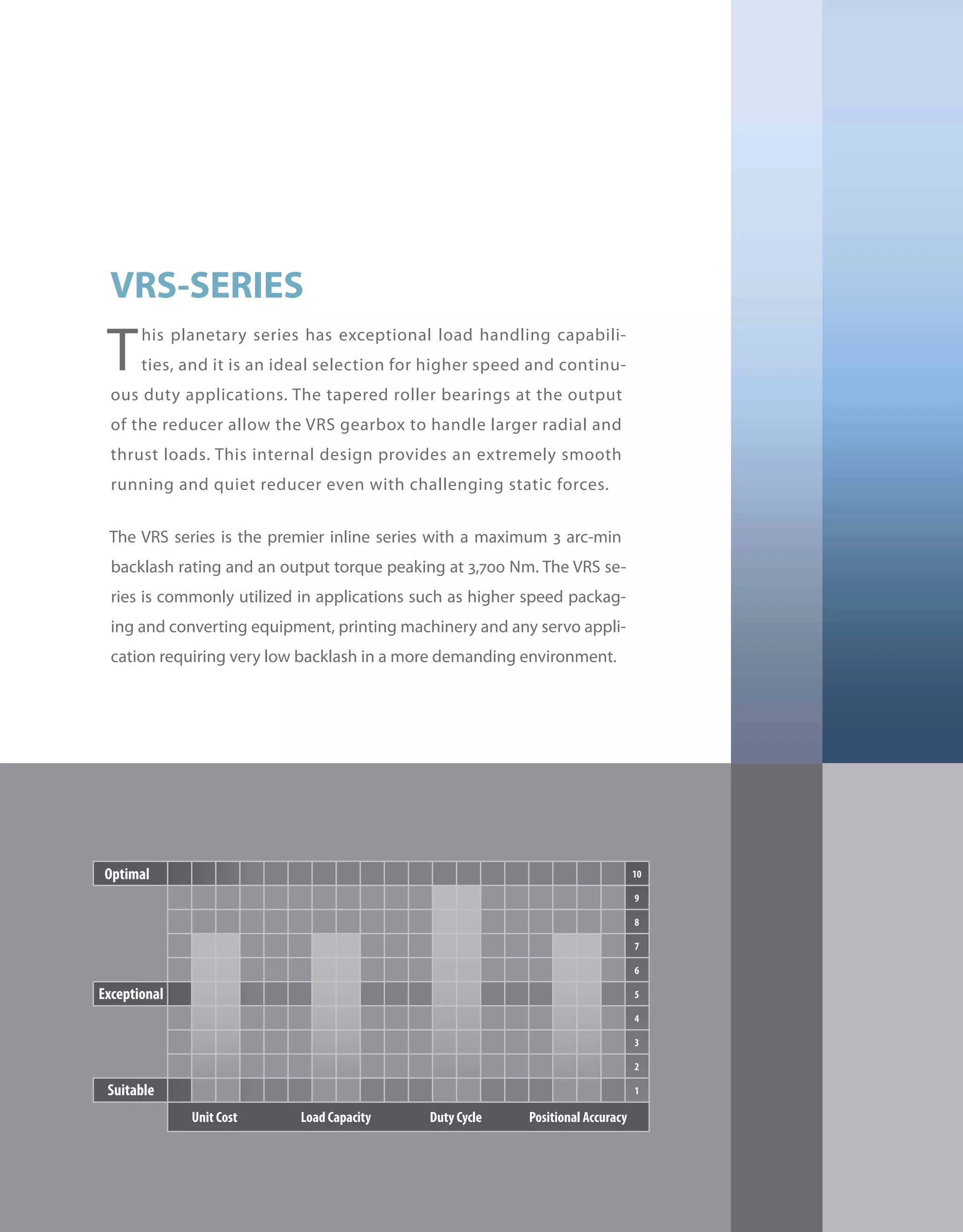


![130
VRS-SERIES Inline shaft
VRS-060 – 1-Stage Specifications
VRS-060 – 2-Stage Specifications
Frame Size 060
Stage 1-Stage
Ratio Unit Note 3 4 5 6 7 8 9 10
Nominal Output Torque [Nm] *1 18 27 27 27 27 27 18 18
Maximum Acceleration Torque [Nm] *2 35 50 50 50 50 50 35 35
Emergency Stop Torque [Nm] *3 80 100 100 100 100 100 80 80
Nominal Input Speed [rpm] *4 3000
Maximum Input Speed [rpm] *5 6000
No Load Running Torque [Nm] *6 0.15
Permitted Radial Load [N] *7 1700 1900 2000 2100 2200 2300 2400 2400
Permitted Axial Load [N] *8 2300 2500 2700 2700 2700 2700 2700 2700
Maximum Radial Load [N] *9 3000
Maximum Axial Load [N] *10 2700
Moment of Inertia (≤Ø 8) [kgcm2] -- 0.150 0.100 0.080 0.070 0.064 0.060 0.058 0.056
Moment of Inertia (≤ Ø 14) [kgcm2] -- 0.230 0.180 0.160 0.150 0.140 0.140 0.140 0.140
Moment of Inertia (≤ Ø 19) [kgcm2] -- 0.440 0.390 0.370 0.360 0.350 0.350 0.350 0.340
Efficiency [%] *11 95
Torsional Rigidity [Nm/arc-min] *12 3
Maximum Torsional Backlash [arc-min] -- ≤ 3
Noise Level [dB] *13 66
Protection Class -- *14 IP54 (IP65)
Ambient Temperature [°C] -- 0-40
Permitted Housing Temperature [°C] -- 90
Weight [kg] *15 1.6
Frame Size 060
Stage 2-Stage
Ratio Unit Note 15 16 20 25 28 30 35 40
Nominal Output Torque [Nm] *1 18 27 27 27 27 18 27 27
Maximum Acceleration Torque [Nm] *2 35 50 50 50 50 35 50 50
Emergency Stop Torque [Nm] *3 80 100 100 100 100 80 100 100
Nominal Input Speed [rpm] *4 3000
Maximum Input Speed [rpm] *5 6000
No Load Running Torque [Nm] *6 0.04
Permitted Radial Load [N] *7 2800 2800 3000 3000 3000 3000 3000 3000
Permitted Axial Load [N] *8 2700 2700 2700 2700 2700 2700 2700 2700
Maximum Radial Load [N] *9 3000
Maximum Axial Load [N] *10 2700
Moment of Inertia (≤Ø 8) [kgcm2] -- 0.055 0.057 0.054 0.053 0.055 0.049 0.053 0.049
Moment of Inertia (≤ Ø 14) [kgcm2] -- 0.140 0.140 0.130 0.130 0.140 0.130 0.130 0.130
Moment of Inertia (≤ Ø 19) [kgcm2] -- -- -- -- -- -- -- -- --
Efficiency [%] *11 90
Torsional Rigidity [Nm/arc-min] *12 3
Maximum Torsional Backlash [arc-min] -- ≤ 3
Noise Level [dB] *13 66
Protection Class -- *14 IP54 (IP65)
Ambient Temperature [°C] -- 0-40
Permitted Housing Temperature [°C] -- 90
Weight [kg] *15 1.8](https://image.slidesharecdn.com/shimpohighprecisioncatalog-140807090507-phpapp01/75/Shimpo-high-precision-catalog-132-2048.jpg)
![131
VRS
VRS-060 – 2-Stage Specifications
Frame Size 060
Stage 2-Stage
Ratio Unit Note 45 50 60 70 80 90 100
Nominal Output Torque [Nm] *1 18 27 27 27 27 18 18
Maximum Acceleration Torque [Nm] *2 35 50 50 50 50 35 35
Emergency Stop Torque [Nm] *3 80 100 100 100 100 80 80
Nominal Input Speed [rpm] *4 3000
Maximum Input Speed [rpm] *5 6000
No Load Running Torque [Nm] *6 0.04
Permitted Radial Load [N] *7 3000 3000 3000 3000 3000 3000 3000
Permitted Axial Load [N] *8 2700 2700 2700 2700 2700 2700 2700
Maximum Radial Load [N] *9 3000
Maximum Axial Load [N] *10 2700
Moment of Inertia (≤Ø 8) [kgcm2] -- 0.053 0.049 0.049 0.049 0.049 0.049 0.049
Moment of Inertia (≤ Ø 14) [kgcm2] -- 0.130 0.130 0.130 0.130 0.130 0.130 0.130
Moment of Inertia (≤ Ø 19) [kgcm2] -- -- -- -- -- -- -- --
Efficiency [%] *11 90
Torsional Rigidity [Nm/arc-min] *12 3
Maximum Torsional Backlash [arc-min] -- ≤ 3
Noise Level [dB] *13 66
Protection Class -- *14 IP54 (IP65)
Ambient Temperature [°C] -- 0-40
Permitted Housing Temperature [°C] -- 90
Weight [kg] *15 1.8
*1) At nominal input speed, service life is 20,000 hours
*2) The maximum torque when starting or stopping operation
*3) The maximum torque allowed under a stress situation (Permitted 1,000 times during service life)
*4) The average input speed
*5) The maximum intermittent input speed
*6) This is the torque at no load applied on the input shaft. The input speed is 3,000 rpm for VRS060
*7) At this load and nominal input speed, service life will be 20,000 hours. (The radial load applied to the output side bearing)
*8) At this load and nominal input speed, service life will be 20,000 hours. (The axial load applied to the output shaft center)
*9) The maximum radial load that the reducer can accept
*10) The maximum axial load that the reducer can accept
*11) The efficiency at the nominal torque rating
*12) This does not include the lost motion
*13) Contact NIDEC-SHIMPO for the testing conditions and environment
*14) IP65 (wash-down) is available as an option. Contact NIDEC-SHIMPO for more details and our food grade options
*15) The weight may vary slightly between models](https://image.slidesharecdn.com/shimpohighprecisioncatalog-140807090507-phpapp01/75/Shimpo-high-precision-catalog-133-2048.jpg)
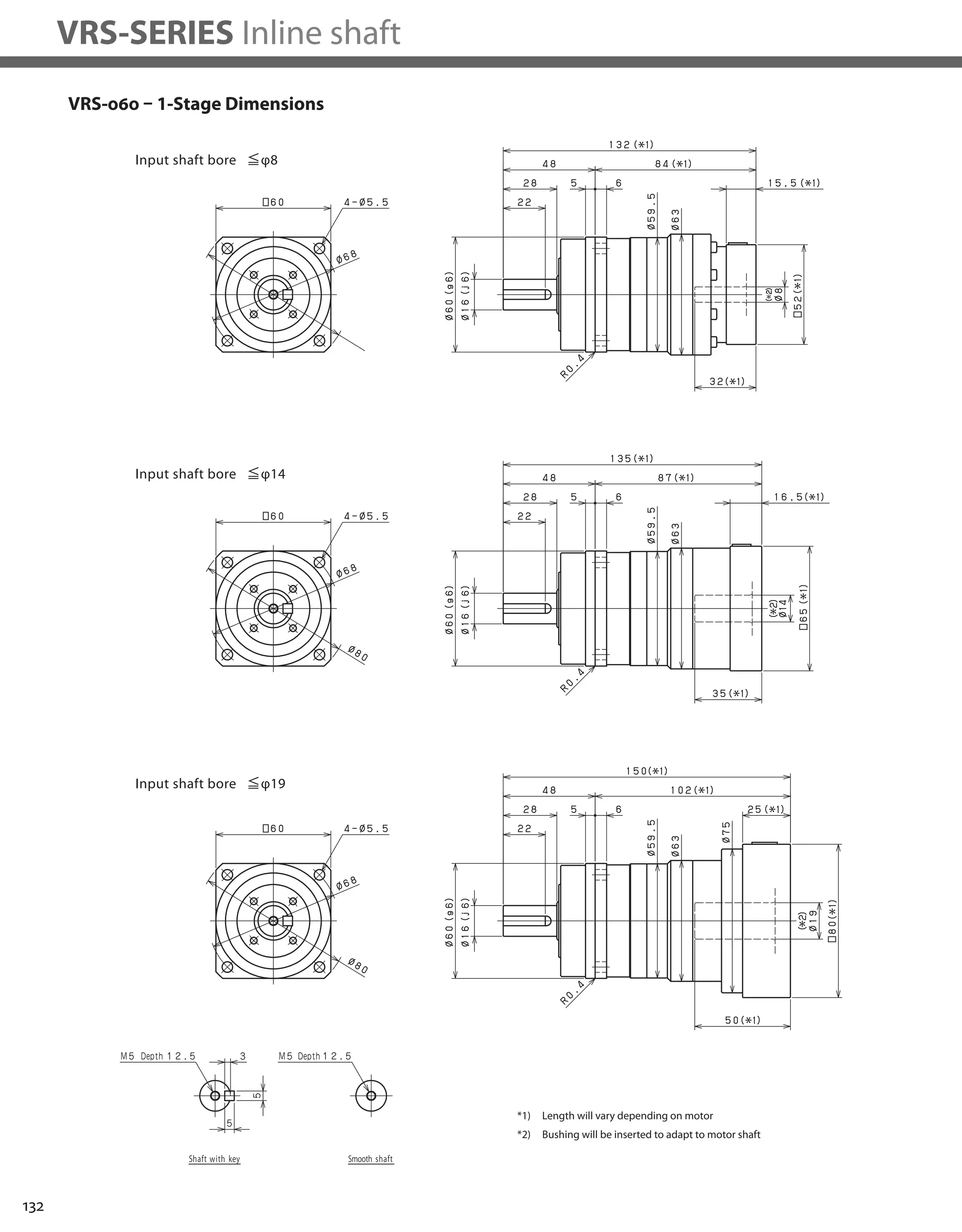

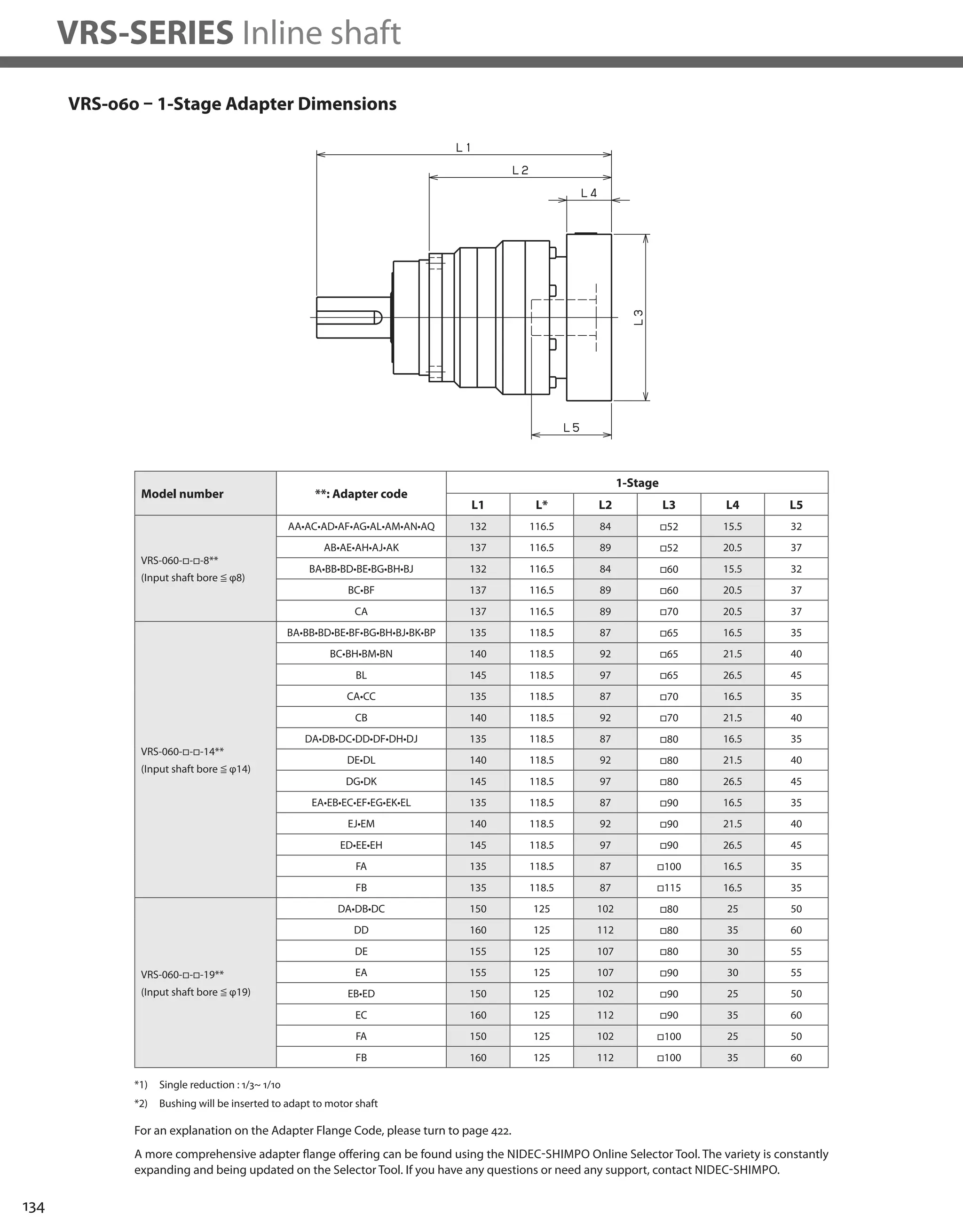

![136
VRS-SERIES Inline shaft
VRS-075 – 1-Stage Specifications
VRS-075 – 2-Stage Specifications
Frame Size 075
Stage 1-Stage
Ratio Unit Note 3 4 5 6 7 8 9 10
Nominal Output Torque [Nm] *1 50 75 75 75 75 75 50 50
Maximum Acceleration Torque [Nm] *2 80 125 125 125 125 125 80 80
Emergency Stop Torque [Nm] *3 200 250 250 250 250 250 200 200
Nominal Input Speed [rpm] *4 3000
Maximum Input Speed [rpm] *5 6000
No Load Running Torque [Nm] *6 0.35
Permitted Radial Load [N] *7 2300 2500 2700 2800 3000 3100 3200 3300
Permitted Axial Load [N] *8 3400 3700 3900 3900 3900 3900 3900 3900
Maximum Radial Load [N] *9 4300
Maximum Axial Load [N] *10 3900
Moment of Inertia (≤Ø 8) [kgcm2] -- -- -- -- -- -- -- -- --
Moment of Inertia (≤ Ø 14) [kgcm2] -- 0.670 0.470 0.380 0.340 0.310 0.300 0.290 0.290
Moment of Inertia (≤ Ø 19) [kgcm2] -- 1.100 0.930 0.850 0.810 0.780 0.760 0.750 0.750
Moment of Inertia (≤ Ø 28) [kgcm2] -- 3.100 2.900 2.900 2.800 2.800 2.800 2.800 2.800
Efficiency [%] *11 95
Torsional Rigidity [Nm/arc-min] *12 10
Maximum Torsional Backlash [arc-min] -- ≤ 3
Noise Level [dB] *13 67
Protection Class -- *14 IP54 (IP65)
Ambient Temperature [°C] -- 0-40
Permitted Housing Temperature [°C] -- 90
Weight [kg] *15 3.4
Frame Size 075
Stage 2-Stage
Ratio Unit Note 15 16 20 25 28 30 35 40
Nominal Output Torque [Nm] *1 50 75 75 75 75 50 75 75
Maximum Acceleration Torque [Nm] *2 80 125 125 125 125 80 125 125
Emergency Stop Torque [Nm] *3 200 250 250 250 250 200 250 250
Nominal Input Speed [rpm] *4 3000
Maximum Input Speed [rpm] *5 6000
No Load Running Torque [Nm] *6 0.06
Permitted Radial Load [N] *7 3700 3800 4000 4300 4300 4300 4300 4300
Permitted Axial Load [N] *8 3900 3900 3900 3900 3900 3900 3900 3900
Maximum Radial Load [N] *9 4300
Maximum Axial Load [N] *10 3900
Moment of Inertia (≤Ø 8) [kgcm2] -- 0.130 0.140 0.130 0.120 0.140 0.099 0.120 0.098
Moment of Inertia (≤ Ø 14) [kgcm2] -- 0.280 0.300 0.280 0.280 0.290 0.250 0.270 0.250
Moment of Inertia (≤ Ø 19) [kgcm2] -- 0.720 0.730 0.720 0.710 0.730 0.700 0.710 0.690
Moment of Inertia (≤ Ø 28) [kgcm2] -- -- -- -- -- -- -- -- --
Efficiency [%] *11 90
Torsional Rigidity [Nm/arc-min] *12 10
Maximum Torsional Backlash [arc-min] -- ≤ 3
Noise Level [dB] *13 67
Protection Class -- *14 IP54 (IP65)
Ambient Temperature [°C] -- 0-40
Permitted Housing Temperature [°C] -- 90
Weight [kg] *15 3.8](https://image.slidesharecdn.com/shimpohighprecisioncatalog-140807090507-phpapp01/75/Shimpo-high-precision-catalog-138-2048.jpg)
![137
VRS
VRS-075 – 2-Stage Specifications
Frame Size 075
Stage 2-Stage
Ratio Unit Note 45 50 60 70 80 90 100
Nominal Output Torque [Nm] *1 50 75 75 75 75 50 50
Maximum Acceleration Torque [Nm] *2 80 125 125 125 125 80 80
Emergency Stop Torque [Nm] *3 200 250 250 250 250 200 200
Nominal Input Speed [rpm] *4 3000
Maximum Input Speed [rpm] *5 6000
No Load Running Torque [Nm] *6 0.06
Permitted Radial Load [N] *7 4300 4300 4300 4300 4300 4300 4300
Permitted Axial Load [N] *8 3900 3900 3900 3900 3900 3900 3900
Maximum Radial Load [N] *9 4300
Maximum Axial Load [N] *10 3900
Moment of Inertia (≤Ø 8) [kgcm2] -- 0.120 0.098 0.098 0.097 0.097 0.097 0.097
Moment of Inertia (≤ Ø 14) [kgcm2] -- 0.270 0.250 0.250 0.250 0.250 0.250 0.250
Moment of Inertia (≤ Ø 19) [kgcm2] -- 0.710 0.690 0.690 0.690 0.690 0.690 0.690
Moment of Inertia (≤ Ø 28) [kgcm2] -- -- -- -- -- -- -- --
Efficiency [%] *11 90
Torsional Rigidity [Nm/arc-min] *12 10
Maximum Torsional Backlash [arc-min] -- ≤ 3
Noise Level [dB] *13 67
Protection Class -- *14 IP54 (IP65)
Ambient Temperature [°C] -- 0-40
Permitted Housing Temperature [°C] -- 90
Weight [kg] *15 3.8
*1) At nominal input speed, service life is 20,000 hours
*2) The maximum torque when starting or stopping operation
*3) The maximum torque allowed under a stress situation (Permitted 1,000 times during service life)
*4) The average input speed
*5) The maximum intermittent input speed
*6) This is the torque at no load applied on the input shaft. The input speed is 3,000 rpm for VRS075
*7) At this load and nominal input speed, service life will be 20,000 hours. (The radial load applied to the output side bearing)
*8) At this load and nominal input speed, service life will be 20,000 hours. (The axial load applied to the output shaft center)
*9) The maximum radial load that the reducer can accept
*10) The maximum axial load that the reducer can accept
*11) The efficiency at the nominal torque rating
*12) This does not include the lost motion
*13) Contact NIDEC-SHIMPO for the testing conditions and environment
*14) IP65 (wash-down) is available as an option. Contact NIDEC-SHIMPO for more details and our food grade options
*15) The weight may vary slightly between models](https://image.slidesharecdn.com/shimpohighprecisioncatalog-140807090507-phpapp01/75/Shimpo-high-precision-catalog-139-2048.jpg)


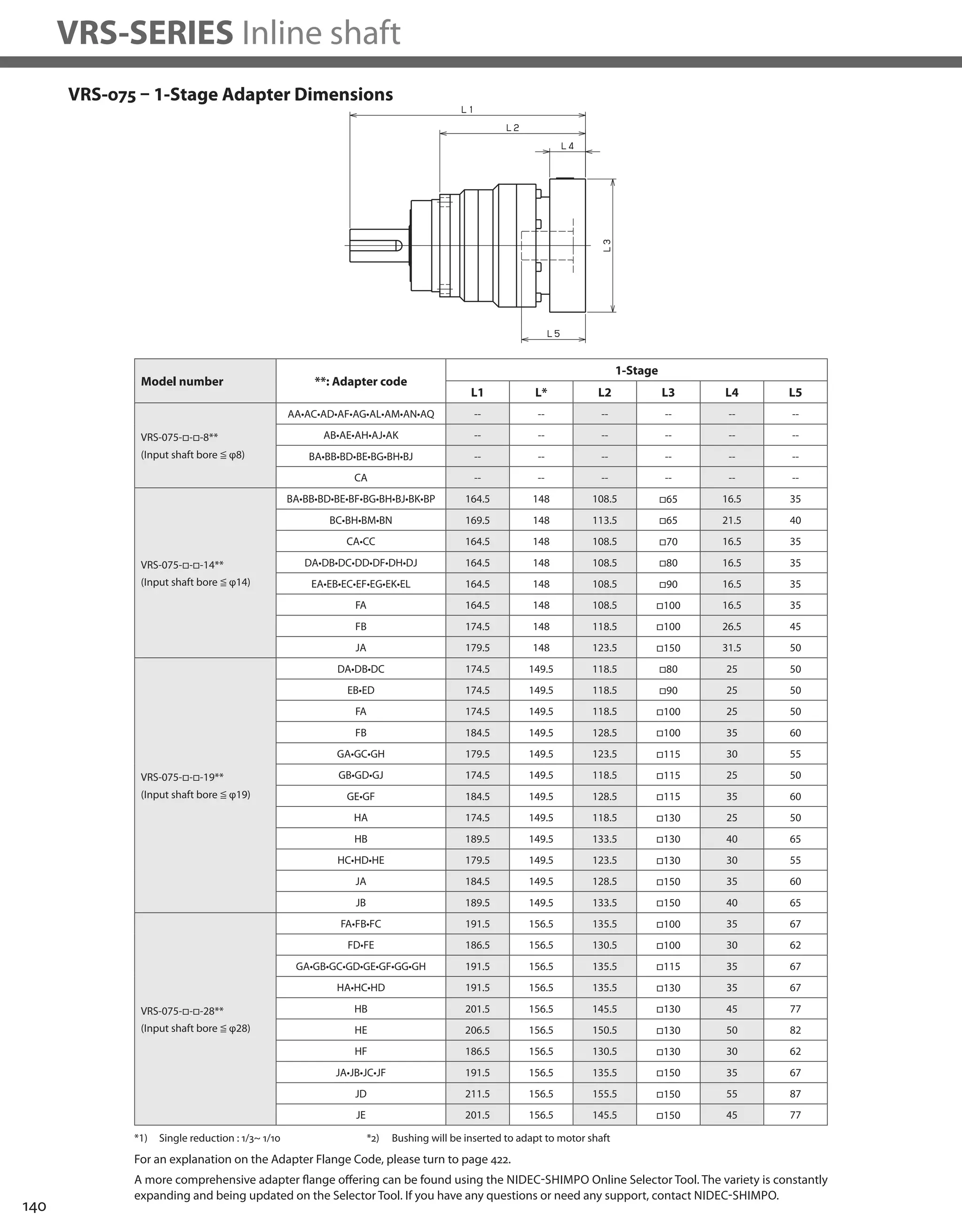

![142
VRS-SERIES Inline shaft
VRS-100 – 1-Stage Specifications
VRS-100 – 2-Stage Specifications
Frame Size 100
Stage 1-Stage
Ratio Unit Note 3 4 5 6 7 8 9 10
Nominal Output Torque [Nm] *1 120 120 180 180 180 180 120 120
Maximum Acceleration Torque [Nm] *2 225 330 330 330 330 330 225 225
Emergency Stop Torque [Nm] *3 500 625 625 625 625 625 500 500
Nominal Input Speed [rpm] *4 3000
Maximum Input Speed [rpm] *5 6000
No Load Running Torque [Nm] *6 1.30
Permitted Radial Load [N] *7 3400 3700 4000 4200 4400 4600 4800 4900
Permitted Axial Load [N] *8 4800 5200 5600 5900 6100 6300 6300 6300
Maximum Radial Load [N] *9 7000
Maximum Axial Load [N] *10 6300
Moment of Inertia (≤Ø 14) [kgcm2] -- -- -- -- -- -- -- -- --
Moment of Inertia (≤ Ø 19) [kgcm2] -- 3.200 2.000 1.500 1.300 1.100 1.000 0.960 0.930
Moment of Inertia (≤ Ø 28) [kgcm2] -- 5.200 4.000 3.600 3.300 3.100 3.000 3.000 3.000
Moment of Inertia (≤ Ø 38) [kgcm2] -- 13.000 12.000 11.000 11.000 11.000 11.000 11.000 11.000
Efficiency [%] *11 95
Torsional Rigidity [Nm/arc-min] *12 31
Maximum Torsional Backlash [arc-min] -- ≤ 3
Noise Level [dB] *13 71
Protection Class -- *14 IP54 (IP65)
Ambient Temperature [°C] -- 0-40
Permitted Housing Temperature [°C] -- 90
Weight [kg] *15 8.1
Frame Size 100
Stage 2-Stage
Ratio Unit Note 15 16 20 25 28 30 35 40
Nominal Output Torque [Nm] *1 120 180 180 180 180 120 180 180
Maximum Acceleration Torque [Nm] *2 225 330 330 330 330 225 330 330
Emergency Stop Torque [Nm] *3 500 625 625 625 625 500 625 625
Nominal Input Speed [rpm] *4 3000
Maximum Input Speed [rpm] *5 6000
No Load Running Torque [Nm] *6 0.42
Permitted Radial Load [N] *7 5600 5700 6100 6500 6700 6900 7000 7000
Permitted Axial Load [N] *8 6300 6300 6300 6300 6300 6300 6300 6300
Maximum Radial Load [N] *9 7000
Maximum Axial Load [N] *10 6300
Moment of Inertia (≤Ø 14) [kgcm2] -- 0.420 0.480 0.400 0.380 0.440 0.290 0.370 0.280
Moment of Inertia (≤ Ø 19) [kgcm2] -- 0.860 0.910 0.830 0.820 0.870 0.740 0.810 0.730
Moment of Inertia (≤ Ø 28) [kgcm2] -- 2.800 2.900 2.800 2.800 2.800 2.700 2.700 2.700
Moment of Inertia (≤ Ø 38) [kgcm2] -- -- -- -- -- -- -- -- --
Efficiency [%] *11 90
Torsional Rigidity [Nm/arc-min] *12 31
Maximum Torsional Backlash [arc-min] -- ≤ 3
Noise Level [dB] *13 71
Protection Class -- *14 IP54 (IP65)
Ambient Temperature [°C] -- 0-40
Permitted Housing Temperature [°C] -- 90
Weight [kg] *15 8.8](https://image.slidesharecdn.com/shimpohighprecisioncatalog-140807090507-phpapp01/75/Shimpo-high-precision-catalog-144-2048.jpg)
![143
VRS
VRS-100 – 2-Stage Specifications
Frame Size 100
Stage 2-Stage
Ratio Unit Note 45 50 60 70 80 90 100
Nominal Output Torque [Nm] *1 120 180 180 180 180 120 120
Maximum Acceleration Torque [Nm] *2 225 330 330 330 330 225 225
Emergency Stop Torque [Nm] *3 500 625 625 625 625 500 500
Nominal Input Speed [rpm] *4 3000
Maximum Input Speed [rpm] *5 6000
No Load Running Torque [Nm] *6 0.42
Permitted Radial Load [N] *7 7000 7000 7000 7000 7000 7000 7000
Permitted Axial Load [N] *8 6300 6300 6300 6300 6300 6300 6300
Maximum Radial Load [N] *9 7000
Maximum Axial Load [N] *10 6300
Moment of Inertia (≤Ø 14) [kgcm2] -- 0.370 0.280 0.280 0.280 0.280 0.270 0.270
Moment of Inertia (≤ Ø 19) [kgcm2] -- 0.800 0.730 0.730 0.730 0.730 0.730 0.730
Moment of Inertia (≤ Ø 28) [kgcm2] -- 2.700 2.700 2.700 2.700 2.700 2.700 2.700
Moment of Inertia (≤ Ø 38) [kgcm2] -- -- -- -- -- -- -- --
Efficiency [%] *11 90
Torsional Rigidity [Nm/arc-min] *12 31
Maximum Torsional Backlash [arc-min] -- ≤ 3
Noise Level [dB] *13 71
Protection Class -- *14 IP54 (IP65)
Ambient Temperature [°C] -- 0-40
Permitted Housing Temperature [°C] -- 90
Weight [kg] *15 8.8
*1) At nominal input speed, service life is 20,000 hours
*2) The maximum torque when starting or stopping operation
*3) The maximum torque allowed under a stress situation (Permitted 1,000 times during service life)
*4) The average input speed
*5) The maximum intermittent input speed
*6) This is the torque at no load applied on the input shaft. The input speed is 3,000 rpm for VRS100
*7) At this load and nominal input speed, service life will be 20,000 hours. (The radial load applied to the output side bearing)
*8) At this load and nominal input speed, service life will be 20,000 hours. (The axial load applied to the output shaft center)
*9) The maximum radial load that the reducer can accept
*10) The maximum axial load that the reducer can accept
*11) The efficiency at the nominal torque rating
*12) This does not include the lost motion
*13) Contact NIDEC-SHIMPO for the testing conditions and environment
*14) IP65 (wash-down) is available as an option. Contact NIDEC-SHIMPO for more details and our food grade options
*15) The weight may vary slightly between models](https://image.slidesharecdn.com/shimpohighprecisioncatalog-140807090507-phpapp01/75/Shimpo-high-precision-catalog-145-2048.jpg)


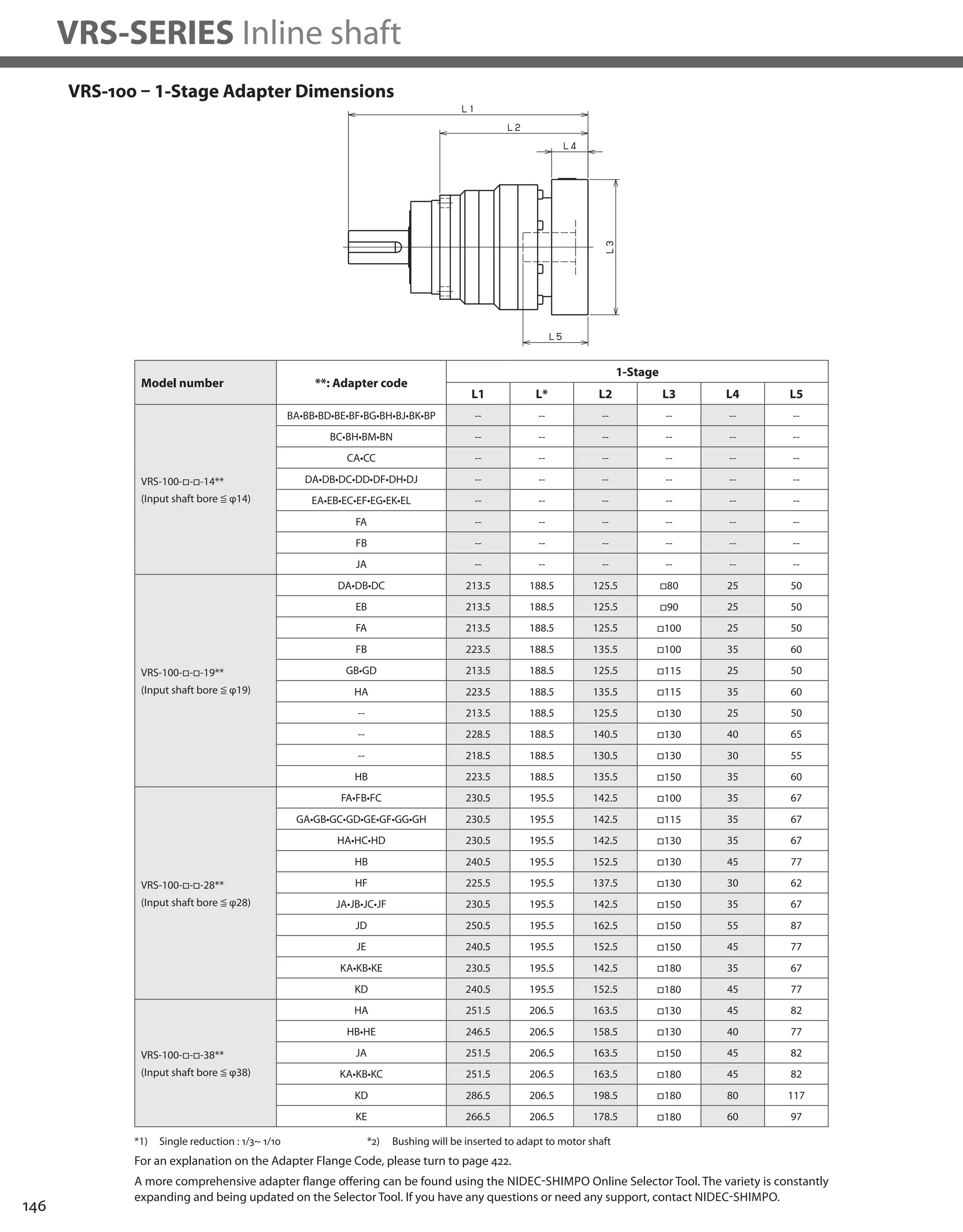
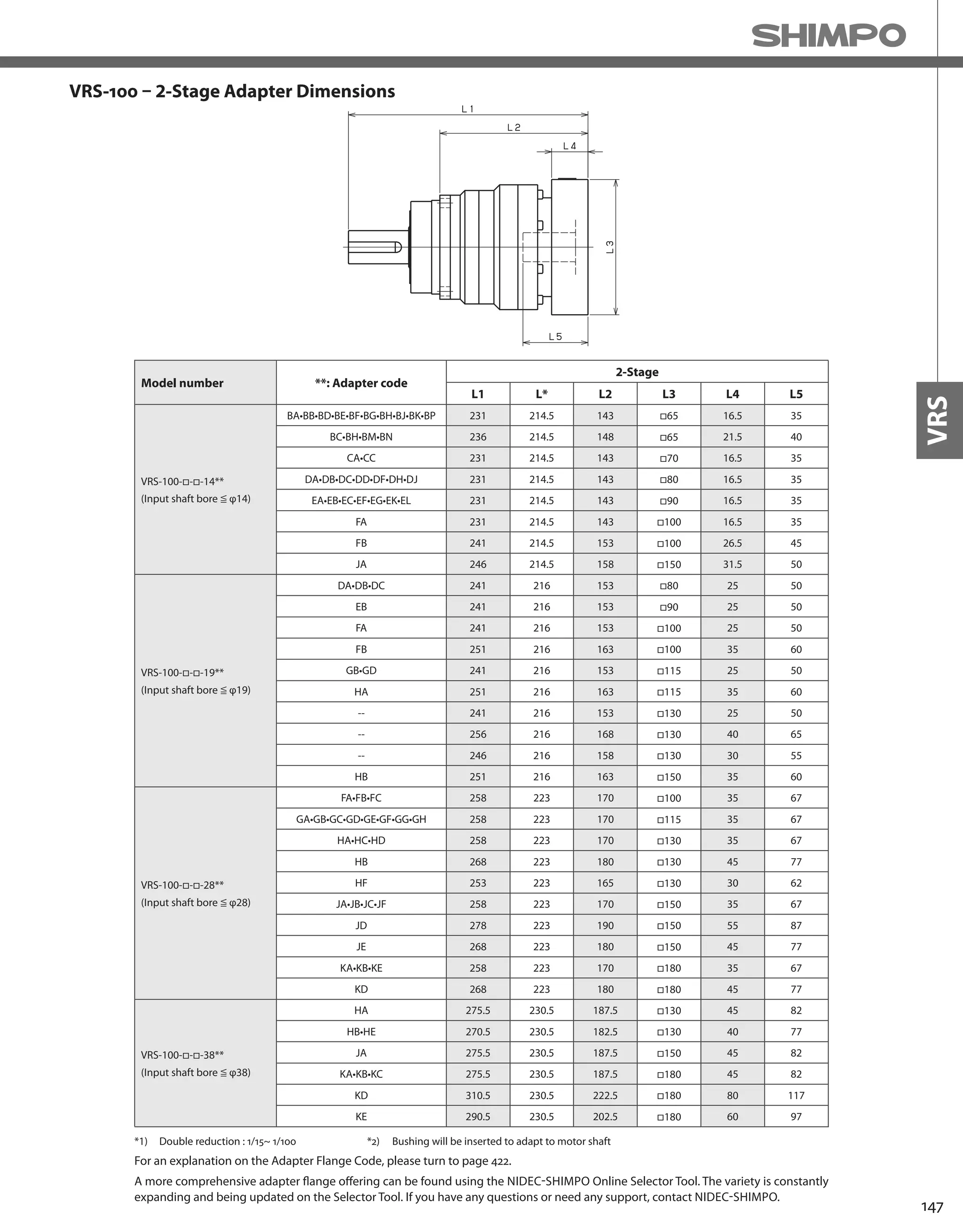
![148
VRS-SERIES Inline shaft
VRS-140 – 1-Stage Specifications
VRS-140 – 2-Stage Specifications
Frame Size 140
Stage 1-Stage
Ratio Unit Note 3 4 5 6 7 8 9 10
Nominal Output Torque [Nm] *1 240 240 360 360 360 360 240 240
Maximum Acceleration Torque [Nm] *2 470 700 700 700 700 700 470 470
Emergency Stop Torque [Nm] *3 1000 1250 1250 1250 1250 1250 1000 1000
Nominal Input Speed [rpm] *4 2000
Maximum Input Speed [rpm] *5 4000
No Load Running Torque [Nm] *6 1.63
Permitted Radial Load [N] *7 6700 7400 7900 8300 8700 9100 9400 9700
Permitted Axial Load [N] *8 9000 9000 9000 9000 9000 9000 9000 9000
Maximum Radial Load [N] *9 10000
Maximum Axial Load [N] *10 9000
Moment of Inertia (≤Ø 19) [kgcm2] -- -- -- -- -- -- -- -- --
Moment of Inertia (≤ Ø 28) [kgcm2] -- 12.000 7.400 5.800 4.900 4.100 3.800 3.600 3.400
Moment of Inertia (≤ Ø 38) [kgcm2] -- 20.000 15.000 13.000 13.000 12.000 12.000 11.000 11.000
Moment of Inertia (≤ Ø 48) [kgcm2] -- 42.000 37.000 36.000 35.000 34.000 34.000 34.000 33.000
Efficiency [%] *11 95
Torsional Rigidity [Nm/arc-min] *12 60
Maximum Torsional Backlash [arc-min] -- ≤ 3
Noise Level [dB] *13 67
Protection Class -- *14 IP54 (IP65)
Ambient Temperature [°C] -- 0-40
Permitted Housing Temperature [°C] -- 90
Weight [kg] *15 17
Frame Size 140
Stage 2-Stage
Ratio Unit Note 15 16 20 25 28 30 35 40
Nominal Output Torque [Nm] *1 240 360 360 360 360 240 360 360
Maximum Acceleration Torque [Nm] *2 470 700 700 700 700 470 700 700
Emergency Stop Torque [Nm] *3 1000 1250 1250 1250 1250 1000 1250 1250
Nominal Input Speed [rpm] *4 2000
Maximum Input Speed [rpm] *5 4000
No Load Running Torque [Nm] *6 0.56
Permitted Radial Load [N] *7 10000 10000 10000 10000 10000 10000 10000 10000
Permitted Axial Load [N] *8 9000 9000 9000 9000 9000 9000 9000 9000
Maximum Radial Load [N] *9 10000
Maximum Axial Load [N] *10 9000
Moment of Inertia (≤Ø 19) [kgcm2] -- 1.300 1.500 1.200 1.100 1.400 0.850 1.100 0.830
Moment of Inertia (≤ Ø 28) [kgcm2] -- 3.200 3.500 3.100 3.100 3.300 2.800 3.100 2.800
Moment of Inertia (≤ Ø 38) [kgcm2] -- 11.000 11.000 11.000 11.000 11.000 10.000 11.000 10.000
Moment of Inertia (≤ Ø 48) [kgcm2] -- -- -- -- -- -- -- -- --
Efficiency [%] *11 90
Torsional Rigidity [Nm/arc-min] *12 60
Maximum Torsional Backlash [arc-min] -- ≤ 3
Noise Level [dB] *13 67
Protection Class -- *14 IP54 (IP65)
Ambient Temperature [°C] -- 0-40
Permitted Housing Temperature [°C] -- 90
Weight [kg] *15 19](https://image.slidesharecdn.com/shimpohighprecisioncatalog-140807090507-phpapp01/75/Shimpo-high-precision-catalog-150-2048.jpg)
![149
VRS
VRS-140 – 2-Stage Specifications
Frame Size 140
Stage 2-Stage
Ratio Unit Note 45 50 60 70 80 90 100
Nominal Output Torque [Nm] *1 240 360 360 360 360 240 240
Maximum Acceleration Torque [Nm] *2 470 700 700 700 700 470 470
Emergency Stop Torque [Nm] *3 1000 1250 1250 1250 1250 1000 1000
Nominal Input Speed [rpm] *4 2000
Maximum Input Speed [rpm] *5 4000
No Load Running Torque [Nm] *6 0.56
Permitted Radial Load [N] *7 10000 10000 10000 10000 10000 10000 10000
Permitted Axial Load [N] *8 9000 9000 9000 9000 9000 9000 9000
Maximum Radial Load [N] *9 10000
Maximum Axial Load [N] *10 9000
Moment of Inertia (≤Ø 19) [kgcm2] -- 1.100 0.810 0.810 0.800 0.800 0.800 0.800
Moment of Inertia (≤ Ø 28) [kgcm2] -- 3.000 2.800 2.800 2.800 2.800 2.800 2.800
Moment of Inertia (≤ Ø 38) [kgcm2] -- 11.000 10.000 10.000 10.000 10.000 10.000 10.000
Moment of Inertia (≤ Ø 48) [kgcm2] -- -- -- -- -- -- -- --
Efficiency [%] *11 90
Torsional Rigidity [Nm/arc-min] *12 60
Maximum Torsional Backlash [arc-min] -- ≤ 3
Noise Level [dB] *13 67
Protection Class -- *14 IP54 (IP65)
Ambient Temperature [°C] -- 0-40
Permitted Housing Temperature [°C] -- 90
Weight [kg] *15 19
*1) At nominal input speed, service life is 20,000 hours
*2) The maximum torque when starting or stopping operation
*3) The maximum torque allowed under a stress situation (Permitted 1,000 times during service life)
*4) The average input speed
*5) The maximum intermittent input speed
*6) This is the torque at no load applied on the input shaft. The input speed is 2,000 rpm for VRS140
*7) At this load and nominal input speed, service life will be 20,000 hours. (The radial load applied to the output side bearing)
*8) At this load and nominal input speed, service life will be 20,000 hours. (The axial load applied to the output shaft center)
*9) The maximum radial load that the reducer can accept
*10) The maximum axial load that the reducer can accept
*11) The efficiency at the nominal torque rating
*12) This does not include the lost motion
*13) Contact NIDEC-SHIMPO for the testing conditions and environment
*14) IP65 (wash-down) is available as an option. Contact NIDEC-SHIMPO for more details and our food grade options
*15) The weight may vary slightly between models](https://image.slidesharecdn.com/shimpohighprecisioncatalog-140807090507-phpapp01/75/Shimpo-high-precision-catalog-151-2048.jpg)

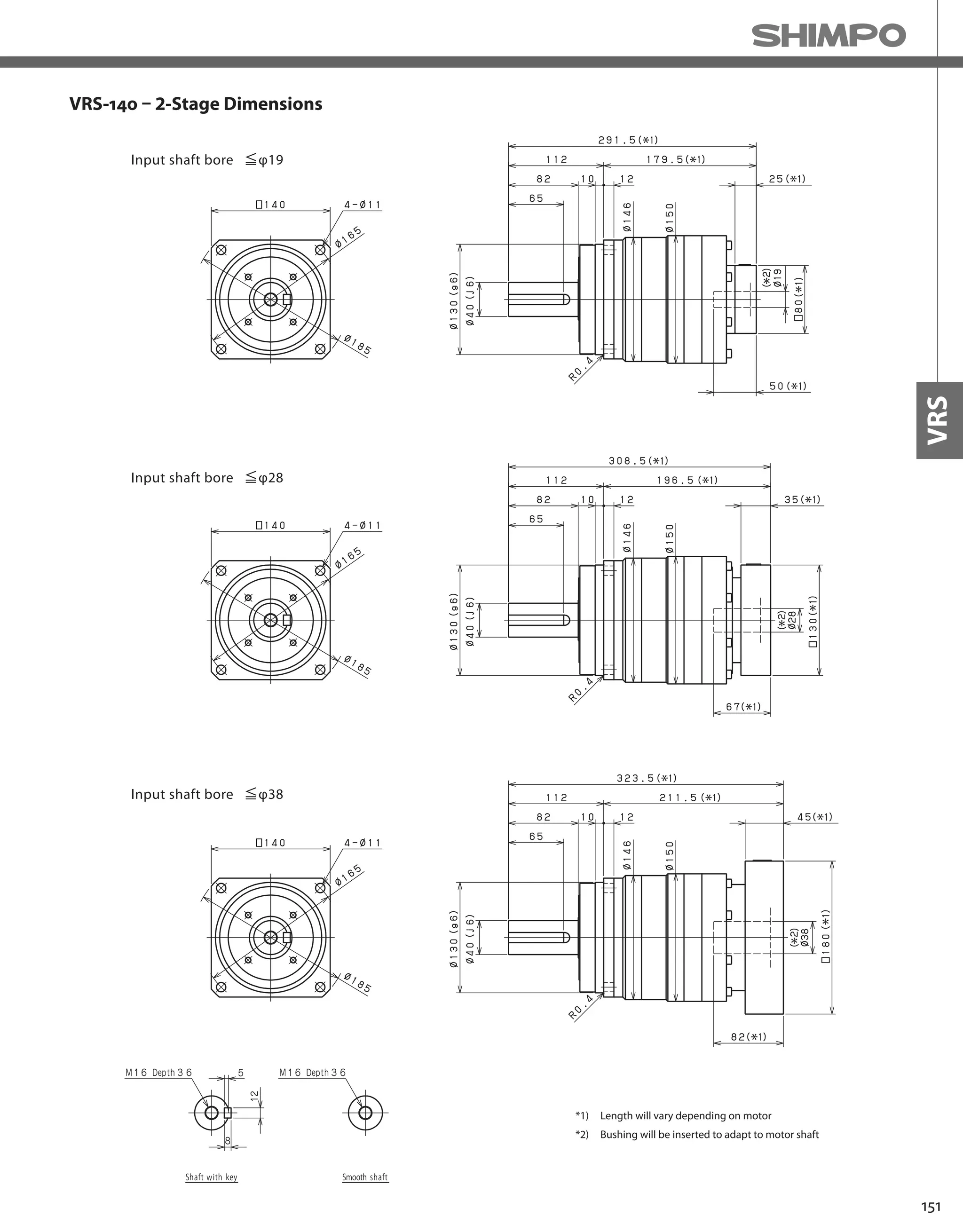
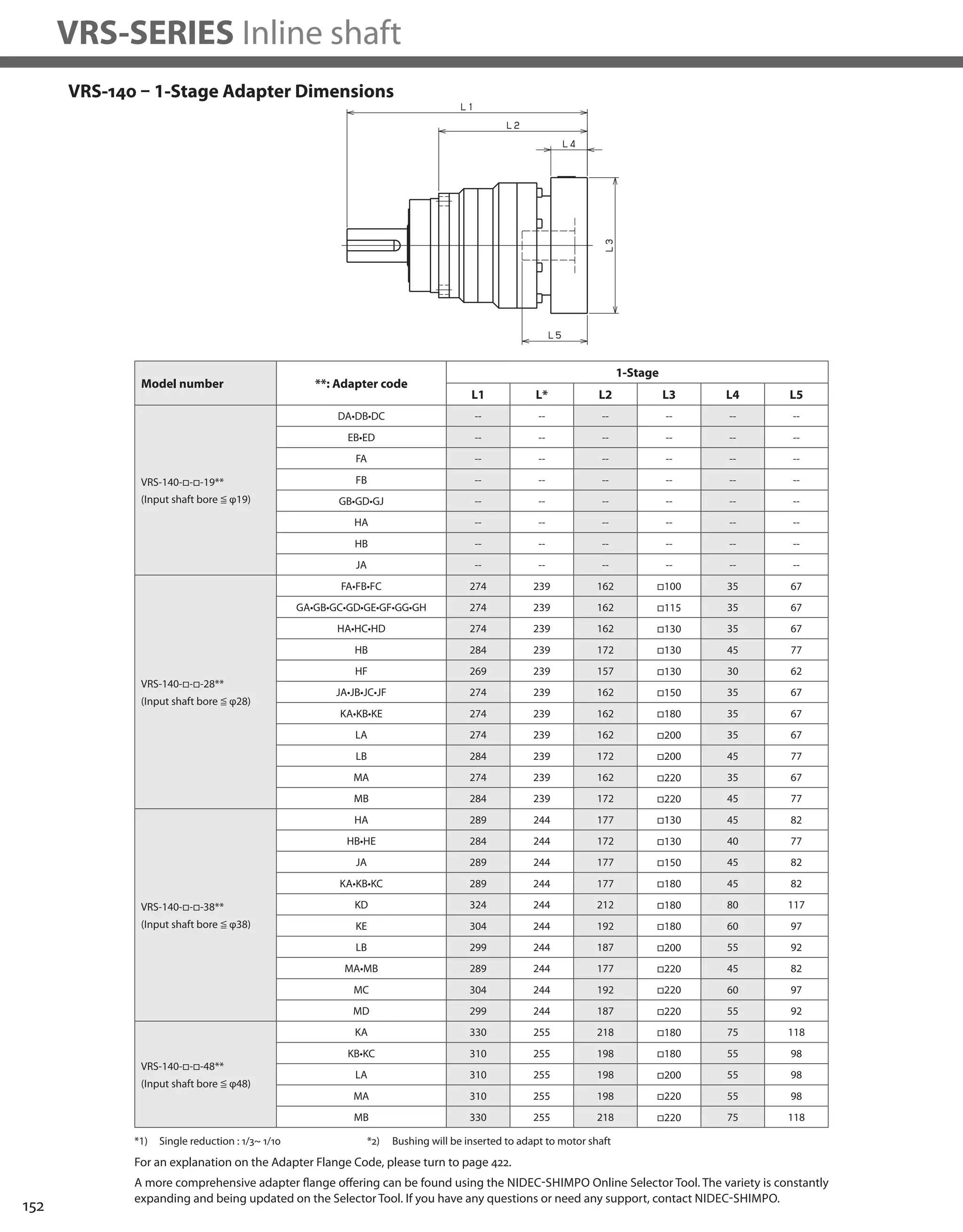

![154
VRS-SERIES Inline shaft
VRS-180 – 1-Stage Specifications
VRS-180 – 2-Stage Specifications
Frame Size 180
Stage 1-Stage
Ratio Unit Note 3 4 5 6 7 8 9 10
Nominal Output Torque [Nm] *1 500 750 750 750 750 750 500 500
Maximum Acceleration Torque [Nm] *2 970 1400 1400 1400 1400 1400 970 970
Emergency Stop Torque [Nm] *3 2200 2750 2750 2750 2750 2750 2200 2200
Nominal Input Speed [rpm] *4 1500
Maximum Input Speed [rpm] *5 3000
No Load Running Torque [Nm] *6 2.68
Permitted Radial Load [N] *7 12000 13000 14000 15000 16000 17000 17000 18000
Permitted Axial Load [N] *8 16000 17000 17000 17000 17000 17000 17000 17000
Maximum Radial Load [N] *9 19000
Maximum Axial Load [N] *10 17000
Moment of Inertia (≤Ø 28) [kgcm2] -- -- -- -- -- -- -- -- --
Moment of Inertia (≤ Ø 38) [kgcm2] -- 42.000 27.000 21.000 18.000 16.000 15.000 14.000 14.000
Moment of Inertia (≤ Ø 48) [kgcm2] -- 64.000 49.000 43.000 40.000 38.000 37.000 36.000 36.000
Moment of Inertia (≤ Ø 65) [kgcm2] -- 120.000 110.000 100.000 100.000 98.000 97.000 96.000 96.000
Efficiency [%] *11 95
Torsional Rigidity [Nm/arc-min] *12 175
Maximum Torsional Backlash [arc-min] -- ≤ 3
Noise Level [dB] *13 67
Protection Class -- *14 IP54 (IP65)
Ambient Temperature [°C] -- 0-40
Permitted Housing Temperature [°C] -- 90
Weight [kg] *15 39
Frame Size 180
Stage 2-Stage
Ratio Unit Note 15 16 20 25 28 30 35 40
Nominal Output Torque [Nm] *1 500 750 750 750 750 500 750 750
Maximum Acceleration Torque [Nm] *2 970 1400 1400 1400 1400 970 1400 1400
Emergency Stop Torque [Nm] *3 2200 2750 2750 2750 2750 2200 2750 2750
Nominal Input Speed [rpm] *4 1500
Maximum Input Speed [rpm] *5 3000
No Load Running Torque [Nm] *6 1.39
Permitted Radial Load [N] *7 19000 19000 19000 19000 19000 19000 19000 19000
Permitted Axial Load [N] *8 17000 17000 17000 17000 17000 17000 17000 17000
Maximum Radial Load [N] *9 19000
Maximum Axial Load [N] *10 17000
Moment of Inertia (≤Ø 28) [kgcm2] -- 4.700 5.400 4.300 4.200 4.900 3.200 4.100 3.200
Moment of Inertia (≤ Ø 38) [kgcm2] -- 12.000 13.000 12.000 12.000 13.000 11.000 12.000 11.000
Moment of Inertia (≤ Ø 48) [kgcm2] -- 34.000 35.000 34.000 34.000 35.000 33.000 34.000 33.000
Moment of Inertia (≤ Ø 65) [kgcm2] -- -- -- -- -- -- -- -- --
Efficiency [%] *11 90
Torsional Rigidity [Nm/arc-min] *12 175
Maximum Torsional Backlash [arc-min] -- ≤ 3
Noise Level [dB] *13 67
Protection Class -- *14 IP54 (IP65)
Ambient Temperature [°C] -- 0-40
Permitted Housing Temperature [°C] -- 90
Weight [kg] *15 39](https://image.slidesharecdn.com/shimpohighprecisioncatalog-140807090507-phpapp01/75/Shimpo-high-precision-catalog-156-2048.jpg)
![155
VRS
VRS-180 – 2-Stage Specifications
Frame Size 180
Stage 2-Stage
Ratio Unit Note 45 50 60 70 80 90 100
Nominal Output Torque [Nm] *1 500 750 750 750 750 500 500
Maximum Acceleration Torque [Nm] *2 970 1400 1400 1400 1400 970 970
Emergency Stop Torque [Nm] *3 2200 2750 2750 2750 2750 2200 2200
Nominal Input Speed [rpm] *4 1500
Maximum Input Speed [rpm] *5 3000
No Load Running Torque [Nm] *6 1.39
Permitted Radial Load [N] *7 19000 19000 19000 19000 19000 19000 19000
Permitted Axial Load [N] *8 17000 17000 17000 17000 17000 17000 17000
Maximum Radial Load [N] *9 19000
Maximum Axial Load [N] *10 17000
Moment of Inertia (≤Ø 28) [kgcm2] -- 4.000 3.100 3.100 3.100 3.100 3.100 3.100
Moment of Inertia (≤ Ø 38) [kgcm2] -- 12.000 11.000 11.000 11.000 11.000 11.000 11.000
Moment of Inertia (≤ Ø 48) [kgcm2] -- 34.000 33.000 33.000 33.000 33.000 33.000 33.000
Moment of Inertia (≤ Ø 65) [kgcm2] -- -- -- -- -- -- -- --
Efficiency [%] *11 90
Torsional Rigidity [Nm/arc-min] *12 175
Maximum Torsional Backlash [arc-min] -- ≤ 3
Noise Level [dB] *13 67
Protection Class -- *14 IP54 (IP65)
Ambient Temperature [°C] -- 0-40
Permitted Housing Temperature [°C] -- 90
Weight [kg] *15 39
*1) At nominal input speed, service life is 20,000 hours
*2) The maximum torque when starting or stopping operation
*3) The maximum torque allowed under a stress situation (Permitted 1,000 times during service life)
*4) The average input speed
*5) The maximum intermittent input speed
*6) This is the torque at no load applied on the input shaft. The input speed is 1,5000 rpm for VRS180
*7) At this load and nominal input speed, service life will be 20,000 hours. (The radial load applied to the output side bearing)
*8) At this load and nominal input speed, service life will be 20,000 hours. (The axial load applied to the output shaft center)
*9) The maximum radial load that the reducer can accept
*10) The maximum axial load that the reducer can accept
*11) The efficiency at the nominal torque rating
*12) This does not include the lost motion
*13) Contact NIDEC-SHIMPO for the testing conditions and environment
*14) IP65 (wash-down) is available as an option. Contact NIDEC-SHIMPO for more details and our food grade options
*15) The weight may vary slightly between models](https://image.slidesharecdn.com/shimpohighprecisioncatalog-140807090507-phpapp01/75/Shimpo-high-precision-catalog-157-2048.jpg)

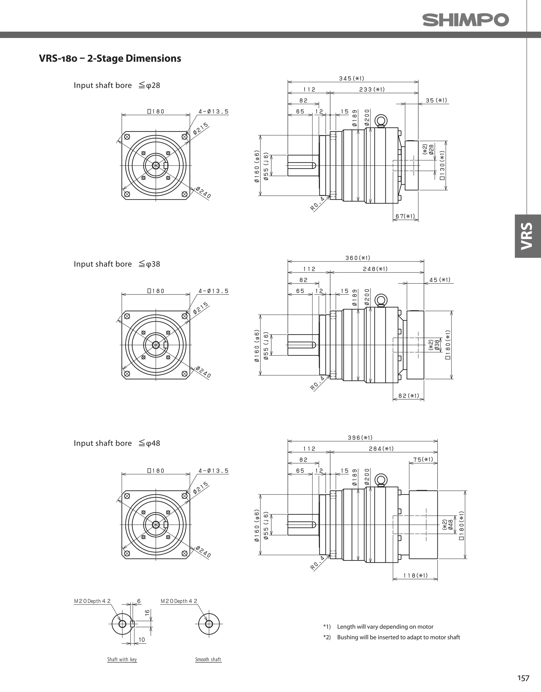


![160
VRS-SERIES Inline shaft
VRS-210 – 1-Stage Specifications
VRS-210 – 2-Stage Specifications
Frame Size 210
Stage 1-Stage
Ratio Unit Note 3 4 5 6 7 8 9 10
Nominal Output Torque [Nm] *1 1000 1500 1500 1500 1500 1500 1000 1000
Maximum Acceleration Torque [Nm] *2 1600 2300 2300 2300 2300 2200 1900 1600
Emergency Stop Torque [Nm] *3 4000 5000 5000 5000 5000 5000 4000 4000
Nominal Input Speed [rpm] *4 1000
Maximum Input Speed [rpm] *5 2000
No Load Running Torque [Nm] *6 2.92
Permitted Radial Load [N] *7 17000 18000 20000 21000 22000 23000 24000 24000
Permitted Axial Load [N] *8 22000 22000 22000 22000 22000 22000 22000 22000
Maximum Radial Load [N] *9 24000
Maximum Axial Load [N] *10 22000
Moment of Inertia (≤Ø 38) [kgcm2] -- -- -- -- -- -- -- -- --
Moment of Inertia (≤ Ø 48) [kgcm2] -- 92.000 63.000 53.000 47.000 43.000 40.000 39.000 38.000
Moment of Inertia (≤ Ø 65) [kgcm2] -- 150.000 120.000 110.000 110.000 100.000 100.000 99.000 98.000
Efficiency [%] *11 97
Torsional Rigidity [Nm/arc-min] *12 400
Maximum Torsional Backlash [arc-min] -- ≤ 3
Noise Level [dB] *13 61
Protection Class -- *14 IP54 (IP65)
Ambient Temperature [°C] -- 0-40
Permitted Housing Temperature [°C] -- 90
Weight [kg] *15 59
Frame Size 210
Stage 2-Stage
Ratio Unit Note 15 16 20 25 28 30 35 40
Nominal Output Torque [Nm] *1 1000 1500 1500 1500 1500 1000 1500 1500
Maximum Acceleration Torque [Nm] *2 1600 2300 2300 2300 2300 1600 2300 2300
Emergency Stop Torque [Nm] *3 4000 5000 5000 5000 5000 4000 5000 5000
Nominal Input Speed [rpm] *4 1000
Maximum Input Speed [rpm] *5 2000
No Load Running Torque [Nm] *6 1.14
Permitted Radial Load [N] *7 24000 24000 24000 24000 24000 24000 24000 24000
Permitted Axial Load [N] *8 22000 22000 22000 22000 22000 22000 22000 22000
Maximum Radial Load [N] *9 24000
Maximum Axial Load [N] *10 22000
Moment of Inertia (≤Ø 38) [kgcm2] -- 14.000 16.000 14.000 14.000 15.000 12.000 13.000 12.000
Moment of Inertia (≤ Ø 48) [kgcm2] -- 36.000 37.000 36.000 35.000 36.000 34.000 35.000 33.000
Moment of Inertia (≤ Ø 65) [kgcm2] -- -- -- -- -- -- -- -- --
Efficiency [%] *11 92
Torsional Rigidity [Nm/arc-min] *12 400
Maximum Torsional Backlash [arc-min] -- ≤ 3
Noise Level [dB] *13 61
Protection Class -- *14 IP54 (IP65)
Ambient Temperature [°C] -- 0-40
Permitted Housing Temperature [°C] -- 90
Weight [kg] *15 60](https://image.slidesharecdn.com/shimpohighprecisioncatalog-140807090507-phpapp01/75/Shimpo-high-precision-catalog-162-2048.jpg)
![161
VRS
VRS-210 – 2-Stage Specifications
Frame Size 210
Stage 2-Stage
Ratio Unit Note 45 50 60 70 80 90 100
Nominal Output Torque [Nm] *1 1000 1500 1500 1500 1500 1000 1000
Maximum Acceleration Torque [Nm] *2 1300 2300 2300 2300 1800 1300 1200
Emergency Stop Torque [Nm] *3 4000 5000 5000 5000 5000 4000 4000
Nominal Input Speed [rpm] *4 1000
Maximum Input Speed [rpm] *5 2000
No Load Running Torque [Nm] *6 1.14
Permitted Radial Load [N] *7 24000 24000 24000 24000 24000 24000 24000
Permitted Axial Load [N] *8 22000 22000 22000 22000 22000 22000 22000
Maximum Radial Load [N] *9 24000
Maximum Axial Load [N] *10 22000
Moment of Inertia (≤Ø 38) [kgcm2] -- 13.000 12.000 12.000 12.000 12.000 12.000 12.000
Moment of Inertia (≤ Ø 48) [kgcm2] -- 35.000 33.000 33.000 33.000 33.000 33.000 33.000
Moment of Inertia (≤ Ø 65) [kgcm2] -- -- -- -- -- -- -- --
Efficiency [%] *11 92
Torsional Rigidity [Nm/arc-min] *12 400
Maximum Torsional Backlash [arc-min] -- ≤ 3
Noise Level [dB] *13 61
Protection Class -- *14 IP54 (IP65)
Ambient Temperature [°C] -- 0-40
Permitted Housing Temperature [°C] -- 90
Weight [kg] *15 60
*1) At nominal input speed, service life is 20,000 hours
*2) The maximum torque when starting or stopping operation
*3) The maximum torque allowed under a stress situation (Permitted 1,000 times during service life)
*4) The average input speed
*5) The maximum intermittent input speed
*6) This is the torque at no load applied on the input shaft. The input speed is 1,5000 rpm for VRS210;
*7) At this load and nominal input speed, service life will be 20,000 hours. (The radial load applied to the output side bearing)
*8) At this load and nominal input speed, service life will be 20,000 hours. (The axial load applied to the output shaft center)
*9) The maximum radial load that the reducer can accept
*10) The maximum axial load that the reducer can accept
*11) The efficiency at the nominal torque rating
*12) This does not include the lost motion
*13) Contact NIDEC-SHIMPO for the testing conditions and environment
*14) IP65 (wash-down) is available as an option. Contact NIDEC-SHIMPO for more details and our food grade options
*15) The weight may vary slightly between models](https://image.slidesharecdn.com/shimpohighprecisioncatalog-140807090507-phpapp01/75/Shimpo-high-precision-catalog-163-2048.jpg)


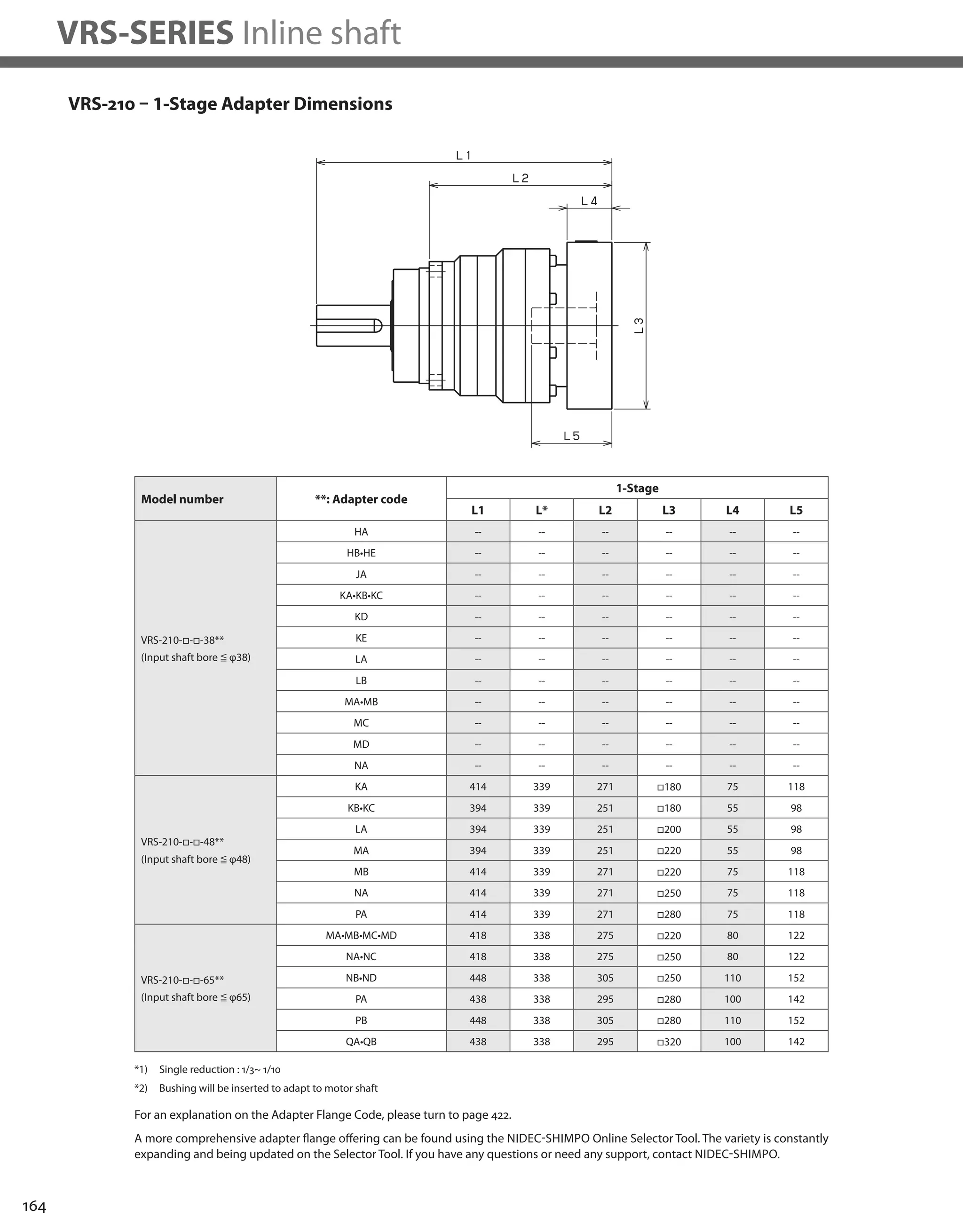

![166
VRS-SERIES Inline shaft
VRS-240 – 1-Stage Specifications
VRS-240 – 2-Stage Specifications
Frame Size 240
Stage 1-Stage
Ratio Unit Note 3 4 5 6 7 8 9 10
Nominal Output Torque [Nm] *1 1600 2400 2400 2400 2400 2400 1600 1600
Maximum Acceleration Torque [Nm] *2 2500 3700 3700 3700 3700 3600 3000 2600
Emergency Stop Torque [Nm] *3 6000 8000 8000 8000 8000 8000 6000 6000
Nominal Input Speed [rpm] *4 1000
Maximum Input Speed [rpm] *5 2000
No Load Running Torque [Nm] *6 5.96
Permitted Radial Load [N] *7 21000 22000 24000 25000 26000 28000 29000 29000
Permitted Axial Load [N] *8 27000 27000 27000 27000 27000 27000 27000 27000
Maximum Radial Load [N] *9 30000
Maximum Axial Load [N] *10 27000
Moment of Inertia (≤Ø 48) [kgcm2] -- -- -- -- -- -- -- -- --
Moment of Inertia (≤ Ø 65) [kgcm2] -- 220.000 160.000 130.000 120.000 110.000 110.000 110.000 100.000
Efficiency [%] *11 97
Torsional Rigidity [Nm/arc-min] *12 550
Maximum Torsional Backlash [arc-min] -- ≤ 3
Noise Level [dB] *13 62
Protection Class -- *14 IP54 (IP65)
Ambient Temperature [°C] -- 0-40
Permitted Housing Temperature [°C] -- 90
Weight [kg] *15 85
Frame Size 240
Stage 2-Stage
Ratio Unit Note 15 16 20 25 28 30 35 40
Nominal Output Torque [Nm] *1 1600 2400 2400 2400 2400 1600 2400 2400
Maximum Acceleration Torque [Nm] *2 2500 3700 3700 3700 3700 2500 3700 3700
Emergency Stop Torque [Nm] *3 6000 8000 8000 8000 8000 6000 8000 8000
Nominal Input Speed [rpm] *4 1000
Maximum Input Speed [rpm] *5 2000
No Load Running Torque [Nm] *6 1.28
Permitted Radial Load [N] *7 30000 30000 30000 30000 30000 30000 30000 30000
Permitted Axial Load [N] *8 27000 27000 27000 27000 27000 27000 27000 27000
Maximum Radial Load [N] *9 30000
Maximum Axial Load [N] *10 27000
Moment of Inertia (≤Ø 48) [kgcm2] -- 40.000 43.000 39.000 39.000 41.000 35.000 38.000 35.000
Moment of Inertia (≤ Ø 65) [kgcm2] -- -- -- -- -- -- -- -- --
Efficiency [%] *11 92
Torsional Rigidity [Nm/arc-min] *12 550
Maximum Torsional Backlash [arc-min] -- ≤ 3
Noise Level [dB] *13 62
Protection Class -- *14 IP54 (IP65)
Ambient Temperature [°C] -- 0-40
Permitted Housing Temperature [°C] -- 90
Weight [kg] *15 89](https://image.slidesharecdn.com/shimpohighprecisioncatalog-140807090507-phpapp01/75/Shimpo-high-precision-catalog-168-2048.jpg)
![167
VRS
VRS-240 – 2-Stage Specifications
Frame Size 240
Stage 2-Stage
Ratio Unit Note 45 50 60 70 80 90 100
Nominal Output Torque [Nm] *1 1600 2400 2400 2400 2400 1600 1600
Maximum Acceleration Torque [Nm] *2 2100 3700 3700 3700 2700 2100 1800
Emergency Stop Torque [Nm] *3 6000 8000 8000 8000 8000 6000 6000
Nominal Input Speed [rpm] *4 1000
Maximum Input Speed [rpm] *5 2000
No Load Running Torque [Nm] *6 1.28
Permitted Radial Load [N] *7 30000 30000 30000 30000 30000 30000 30000
Permitted Axial Load [N] *8 27000 27000 27000 27000 27000 27000 27000
Maximum Radial Load [N] *9 30000
Maximum Axial Load [N] *10 27000
Moment of Inertia (≤Ø 48) [kgcm2] -- 38.000 35.000 35.000 34.000 34.000 34.000 34.000
Moment of Inertia (≤ Ø 65) [kgcm2] -- -- -- -- -- -- -- --
Efficiency [%] *11 92
Torsional Rigidity [Nm/arc-min] *12 550
Maximum Torsional Backlash [arc-min] -- ≤ 3
Noise Level [dB] *13 62
Protection Class -- *14 IP54 (IP65)
Ambient Temperature [°C] -- 0-40
Permitted Housing Temperature [°C] -- 90
Weight [kg] *15 89
*1) At nominal input speed, service life is 20,000 hours
*2) The maximum torque when starting or stopping operation
*3) The maximum torque allowed under a stress situation (Permitted 1,000 times during service life)
*4) The average input speed
*5) The maximum intermittent input speed
*6) This is the torque at no load applied on the input shaft. The input speed is 1,000 rpm for VRS240
*7) At this load and nominal input speed, service life will be 20,000 hours. (The radial load applied to the output side bearing)
*8) At this load and nominal input speed, service life will be 20,000 hours. (The axial load applied to the output shaft center)
*9) The maximum radial load that the reducer can accept
*10) The maximum axial load that the reducer can accept
*11) The efficiency at the nominal torque rating
*12) This does not include the lost motion
*13) Contact NIDEC-SHIMPO for the testing conditions and environment
*14) IP65 (wash-down) is available as an option. Contact NIDEC-SHIMPO for more details and our food grade options
*15) The weight may vary slightly between models](https://image.slidesharecdn.com/shimpohighprecisioncatalog-140807090507-phpapp01/75/Shimpo-high-precision-catalog-169-2048.jpg)


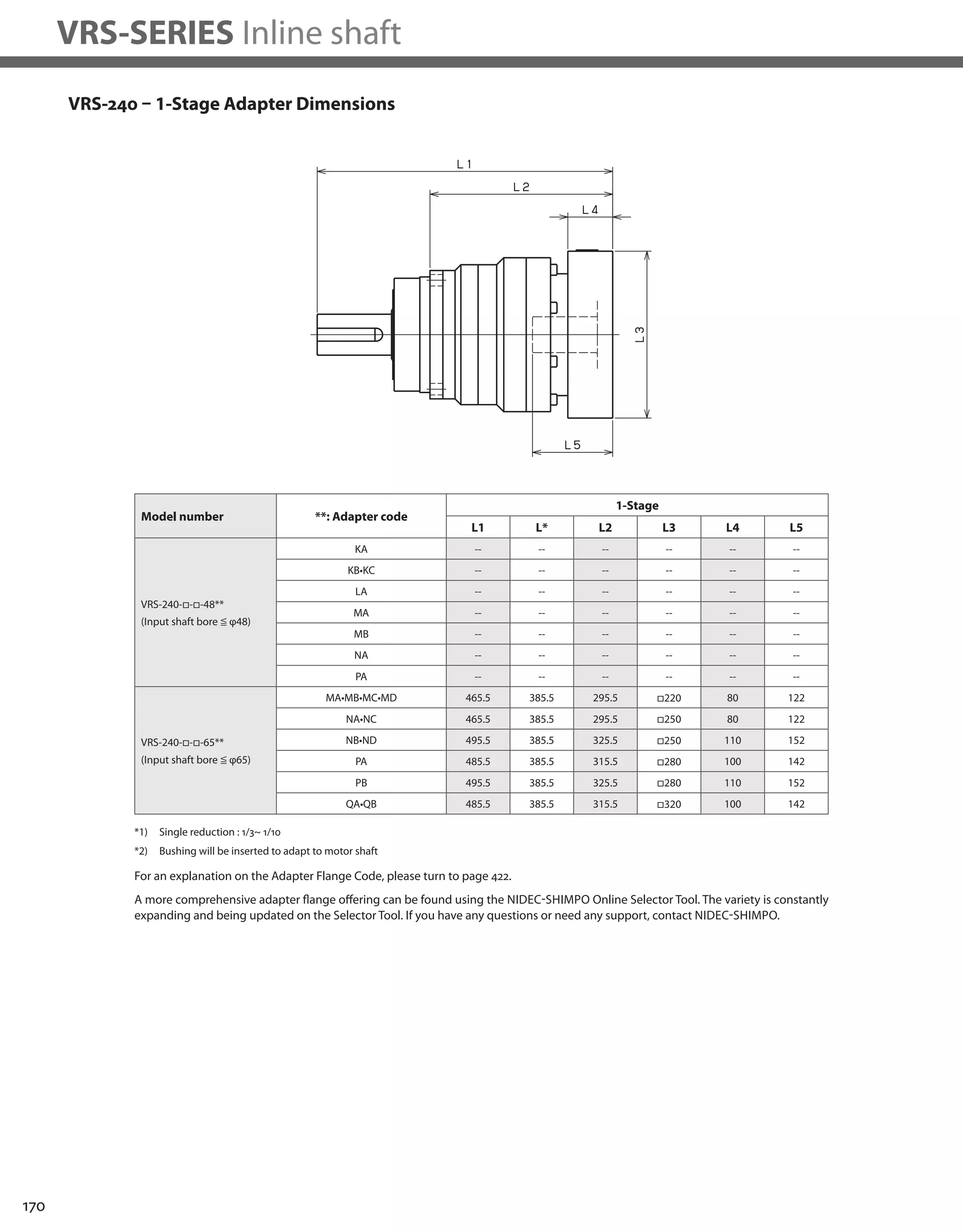


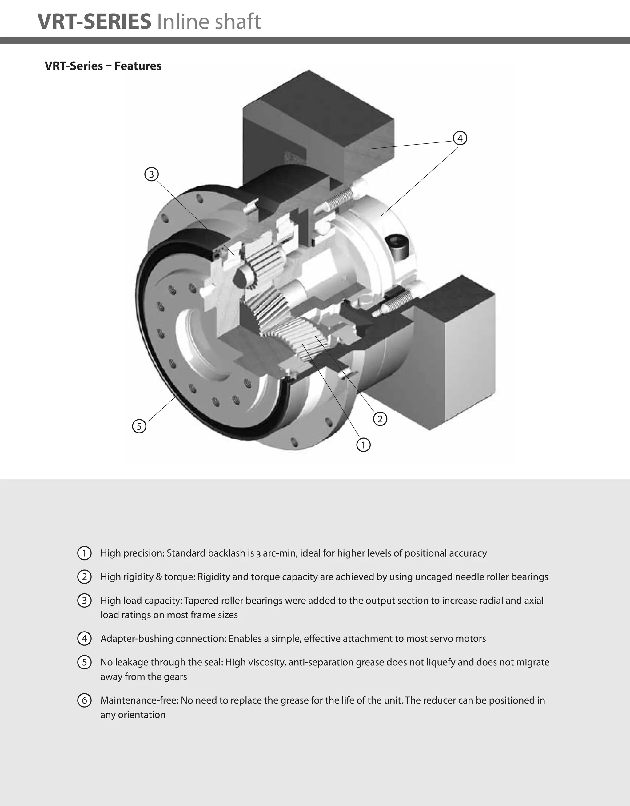
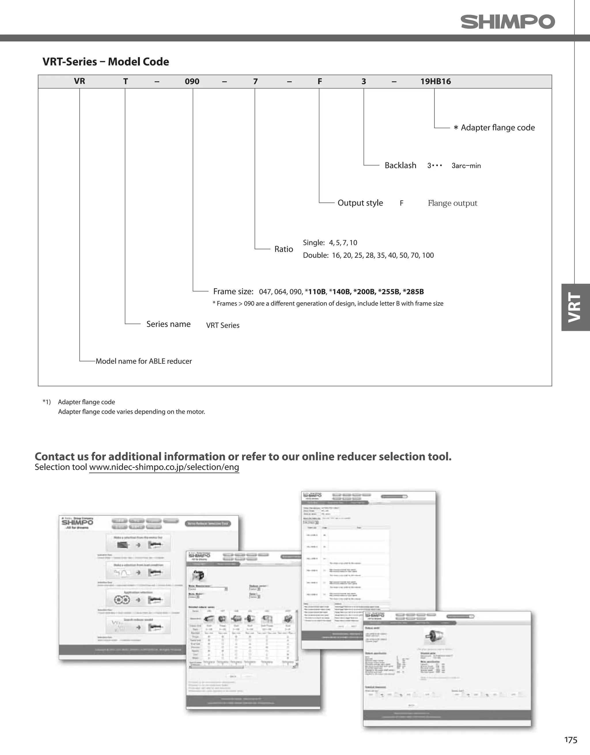
![176
VRT-SERIES Inline shaft
Frame Size 047
Stage 1-Stage
Ratio Unit Notes 4 5 6 7 8 9 10
Nominal Output Torque [Nm] *1 9 9 9 9 9 6 6
Maximum Acceleration Torque [Nm] *2 18 18 18 18 18 12 12
Emergency Stop Torque [Nm] *3 35 35 35 35 35 30 30
Nominal Input Speed [rpm] *4 4000
Maximum Input Speed [rpm] *5 8000
No Load Running Torque [Nm] *6 0.03
Permitted Radial Load [N] *7 270 300 310 330 350 360 370
Permitted Axial Load [N] *8 300 330 360 390 410 430 450
Maximum Radial Load [N] *9 1100
Maximum Axial Load [N] *10 550
Moment of Inertia (≤ Ø 8) [kgcm2] -- 0.052 0.043 0.038 0.036 0.034 0.033 0.032
Moment of Inertia (≤ Ø 14) [kgcm2] -- 0.090 0.081 0.077 0.074 0.072 0.071 0.071
Efficiency [%] *11 95
Torsional Rigidity [Nm/arc-min] *12 2
Maximum Torsional Backlash [arc-min] -- ≤ 3
Noise Level [dB] *13 ≤ 61
Protection Class -- *14 IP54 (IP65)
Ambient Temperature [°C] -- 0 - 40
Permitted Housing Temperature [°C] -- 90
Weight [kg] *15 0.7
Frame Size 047
Stage 2-Stage
Ratio Unit Notes 16 20 25 28 35 40 45
Nominal Output Torque [Nm] *1 9 9 9 9 9 9 6
Maximum Acceleration Torque [Nm] *2 18 18 18 18 18 18 12
Emergency Stop Torque [Nm] *3 35 35 35 35 35 35 30
Nominal Input Speed [rpm] *4 4000
Maximum Input Speed [rpm] *5 8000
No Load Running Torque [Nm] *6 0.01
Permitted Radial Load [N] *7 440 470 510 530 570 590 620
Permitted Axial Load [N] *8 550 550 550 550 550 550 550
Maximum Radial Load [N] *9 1100
Maximum Axial Load [N] *10 550
Moment of Inertia (≤ Ø 8) [kgcm2] -- 0.039 0.035 0.034 0.038 0.034 0.030 0.034
Moment of Inertia (≤ Ø 14) [kgcm2] -- -- -- -- -- -- -- --
Efficiency [%] *11 90
Torsional Rigidity [Nm/arc-min] *12 2
Maximum Torsional Backlash [arc-min] -- ≤ 5
Noise Level [dB] *13 ≤ 61
Protection Class -- *14 IP54 (IP65)
Ambient Temperature [°C] -- 0 - 40
Permitted Housing Temperature [°C] -- 90
Weight [kg] *15 0.8
VRT-047 – 1-Stage Specifications
VRT-047 – 2-Stage Specifications](https://image.slidesharecdn.com/shimpohighprecisioncatalog-140807090507-phpapp01/75/Shimpo-high-precision-catalog-178-2048.jpg)
![177
VRT
Frame Size 047
Stage 2-Stage
Ratio Unit Notes 50 60 70 80 90 100
Nominal Output Torque [Nm] *1 9 9 9 9 6 6
Maximum Acceleration Torque [Nm] *2 18 18 18 18 12 12
Emergency Stop Torque [Nm] *3 35 35 35 35 30 30
Nominal Input Speed [rpm] *4 4000
Maximum Input Speed [rpm] *5 8000
No Load Running Torque [Nm] *6 0.01
Permitted Radial Load [N] *7 640 680 710 750 780 800
Permitted Axial Load [N] *8 550 550 550 550 550 550
Maximum Radial Load [N] *9 1100
Maximum Axial Load [N] *10 550
Moment of Inertia (≤ Ø 8) [kgcm2] -- 0.030 0.030 0.030 0.030 0.030 0.030
Moment of Inertia (≤ Ø 14) [kgcm2] -- -- -- -- -- -- --
Efficiency [%] *11 90
Torsional Rigidity [Nm/arc-min] *12 2
Maximum Torsional Backlash [arc-min] -- ≤ 5
Noise Level [dB] *13 ≤ 61
Protection Class -- *14 IP54 (IP65)
Ambient Temperature [°C] -- 0 - 40
Permitted Housing Temperature [°C] -- 90
Weight [kg] *15 0.8
VRT-047 – 2-Stage Specifications
*1) At nominal input speed, service life is 20,000 hours
*2) The maximum torque when starting or stopping operation
*3) The maximum torque allowed under a stress situation (Permitted 1,000 times during service life)
*4) The average input speed
*5) The maximum intermittent input speed
*6) This is the torque at no load applied on the input shaft. The input speed is 4,000 rpm for VRT 047
*7) At this load and nominal input speed, service life will be 20,000 hours. (The radial load applied to the output side bearing)
*8) At this load and nominal input speed, service life will be 20,000 hours. (The axial load applied to the output flange center)
*9) The maximum radial load that the reducer can accept
*10) The maximum axial load that the reducer can accept
*11) The efficiency at the nominal torque rating
*12) This does not include the lost motion
*13) Contact NIDEC-SHIMPO for the testing conditions and environment
*14) IP65 (wash-down) is available as an option. Contact NIDEC-SHIMPO for more details and our food grade options
*15) The weight may vary slightly between models](https://image.slidesharecdn.com/shimpohighprecisioncatalog-140807090507-phpapp01/75/Shimpo-high-precision-catalog-179-2048.jpg)


![182
VRT-SERIES Inline shaft
VRT-064 – 1-Stage Specifications
Frame Size 064
Stage 1-Stage
Ratio Unit Note 4 5 6 7 8 9 10
Nominal Output Torque [Nm] *1 27 27 27 27 27 18 18
Maximum Acceleration Torque [Nm] *2 50 50 50 50 50 35 35
Emergency Stop Torque [Nm] *3 100 100 100 100 100 80 80
Nominal Input Speed [rpm] *4 3000
Maximum Input Speed [rpm] *5 6000
No Load Running Torque [Nm] *6 0.08
Permitted Radial Load [N] *7 370 400 420 440 460 480 500
Permitted Axial Load [N] *8 360 390 430 460 480 510 530
Maximum Radial Load [N] *9 1500
Maximum Axial Load [N] *10 750
Moment of Inertia (≤ Ø 8) [kgcm2] -- 0.130 0.100 0.085 0.075 0.068 0.064 0.062
Moment of Inertia (≤ Ø 14) [kgcm2] -- 0.210 0.180 0.170 0.150 0.150 0.140 0.140
Moment of Inertia (≤ Ø 19) [kgcm2] -- 0.400 0.400 0.400 0.400 0.400 0.400 0.400
Efficiency [%] *11 95
Torsional Rigidity [Nm/arc-min] *12 3
Maximum Torsional Backlash [arc-min] -- ≤ 3
Noise Level [dB] *13 ≤ 66
Protection Class -- *14 IP54 (IP65)
Ambient Temperature [°C] -- 0 - 40
Permitted Housing Temperature [°C] -- 90
Weight [kg] *15 1.4
Frame Size 064
Stage 2-Stage
Ratio Unit Note 16 20 25 28 35 40 45
Nominal Output Torque [Nm] *1 27 27 27 27 27 27 18
Maximum Acceleration Torque [Nm] *2 50 50 50 50 50 50 35
Emergency Stop Torque [Nm] *3 100 100 100 100 100 100 80
Nominal Input Speed [rpm] *4 3000
Maximum Input Speed [rpm] *5 6000
No Load Running Torque [Nm] *6 0.04
Permitted Radial Load [N] *7 580 630 680 700 760 790 820
Permitted Axial Load [N] *8 650 720 750 750 750 750 750
Maximum Radial Load [N] *9 1500
Maximum Axial Load [N] *10 750
Moment of Inertia (≤ Ø 8) [kgcm2] -- 0.059 0.055 0.054 0.056 0.053 0.049 0.530
Moment of Inertia (≤ Ø 14) [kgcm2] -- 0.140 0.140 0.130 0.140 0.130 0.130 0.130
Moment of Inertia (≤ Ø 19) [kgcm2] -- 0.360 0.350 0.350 0.360 0.350 0.340 0.350
Efficiency [%] *11 90
Torsional Rigidity [Nm/arc-min] *12 3
Maximum Torsional Backlash [arc-min] -- ≤ 3
Noise Level [dB] *13 ≤ 66
Protection Class -- *14 IP54 (IP65)
Ambient Temperature [°C] -- 0 - 40
Permitted Housing Temperature [°C] -- 90
Weight [kg] *15 1.6
VRT-064 – 2-Stage Specifications](https://image.slidesharecdn.com/shimpohighprecisioncatalog-140807090507-phpapp01/75/Shimpo-high-precision-catalog-184-2048.jpg)
![183
VRT
VRT-064 – 2-Stage Specifications
Frame Size 064
Stage 2-Stage
Ratio Unit Note 50 60 70 80 90 100
Nominal Output Torque [Nm] *1 27 27 27 27 18 18
Maximum Acceleration Torque [Nm] *2 50 50 50 50 35 35
Emergency Stop Torque [Nm] *3 100 100 100 100 80 80
Nominal Input Speed [rpm] *4 3000
Maximum Input Speed [rpm] *5 6000
No Load Running Torque [Nm] *6 0.04
Permitted Radial Load [N] *7 850 910 950 1000 1000 1100
Permitted Axial Load [N] *8 750 750 750 750 750 750
Maximum Radial Load [N] *9 1500
Maximum Axial Load [N] *10 750
Moment of Inertia (≤ Ø 8) [kgcm2] -- 0.049 0.049 0.049 0.049 0.049 0.049
Moment of Inertia (≤ Ø 14) [kgcm2] -- 0.130 0.130 0.130 0.130 0.130 0.130
Moment of Inertia (≤ Ø 19) [kgcm2] -- 0.340 0.340 0.340 0.340 0.340 0.340
Efficiency [%] *11 90
Torsional Rigidity [Nm/arc-min] *12 3
Maximum Torsional Backlash [arc-min] -- ≤ 3
Noise Level [dB] *13 ≤ 66
Protection Class -- *14 IP54 (IP65)
Ambient Temperature [°C] -- 0 - 40
Permitted Housing Temperature [°C] -- 90
Weight [kg] *15 1.6
*1) At nominal input speed, service life is 20,000 hours
*2) The maximum torque when starting or stopping operation
*3) The maximum torque allowed under a stress situation (Permitted 1,000 times during service life)
*4) The average input speed
*5) The maximum intermittent input speed
*6) This is the torque at no load applied on the input shaft. The input speed is 3,000 rpm for VRT 064
*7) At this load and nominal input speed, service life will be 20,000 hours. (The radial load applied to the output side bearing)
*8) At this load and nominal input speed, service life will be 20,000 hours. (The axial load applied to the output flange center)
*9) The maximum radial load that the reducer can accept
*10) The maximum axial load that the reducer can accept
*11) The efficiency at the nominal torque rating
*12) This does not include the lost motion
*13) Contact NIDEC-SHIMPO for the testing conditions and environment
*14) IP65 (wash-down) is available as an option. Contact NIDEC-SHIMPO for more details and our food grade options
*15) The weight may vary slightly between models](https://image.slidesharecdn.com/shimpohighprecisioncatalog-140807090507-phpapp01/75/Shimpo-high-precision-catalog-185-2048.jpg)
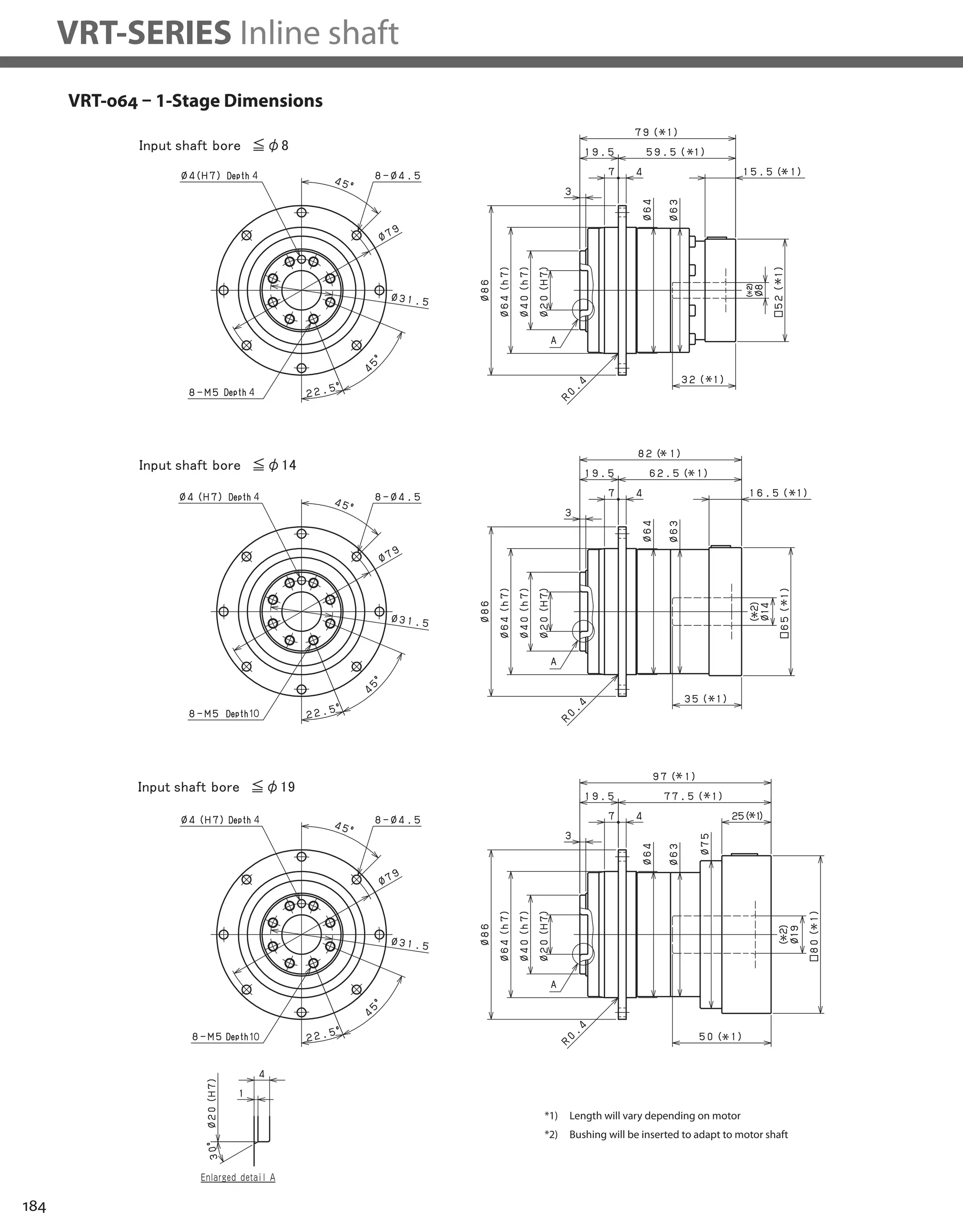


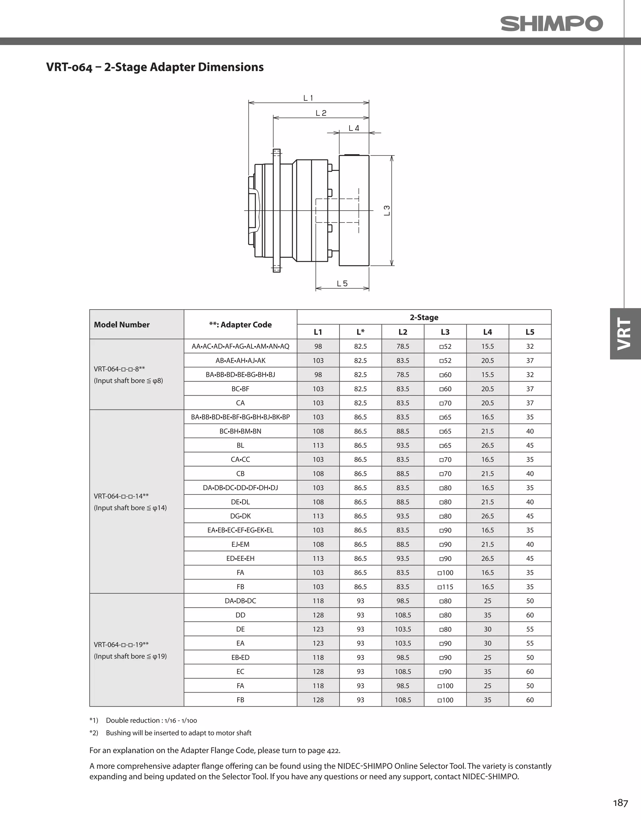
![188
VRT-SERIES Inline shaft
VRT-090 – 1-Stage Specifications
VRT-090 – 2-Stage Specifications
Frame Size 090
Stage 1-Stage
Ratio Unit Note 4 5 6 7 8 9 10
Nominal Output Torque [Nm] *1 75 75 75 75 75 50 50
Maximum Acceleration Torque [Nm] *2 125 125 125 125 125 80 80
Emergency Stop Torque [Nm] *3 250 250 250 250 250 200 200
Nominal Input Speed [rpm] *4 3000
Maximum Input Speed [rpm] *5 6000
No Load Running Torque [Nm] *6 0.17
Permitted Radial Load [N] *7 720 780 830 870 910 950 980
Permitted Axial Load [N] *8 620 680 740 790 830 880 920
Maximum Radial Load [N] *9 3300
Maximum Axial Load [N] *10 1700
Moment of Inertia (≤ Ø 8) [kgcm2] -- - - - - - - -
Moment of Inertia (≤ Ø 14) [kgcm2] -- 0.770 0.580 0.480 0.410 0.370 0.350 0.330
Moment of Inertia (≤ Ø 19) [kgcm2] -- 1.200 1.000 0.940 0.880 0.840 0.810 0.800
Moment of Inertia (≤ Ø 28) [kgcm2] -- 2.900 2.900 2.800 2.800 2.800 2.800 2.800
Efficiency [%] *11 95
Torsional Rigidity [Nm/arc-min] *12 10
Maximum Torsional Backlash [arc-min] -- ≤ 3
Noise Level [dB] *13 ≤ 67
Protection Class -- *14 IP54 (IP65)
Ambient Temperature [°C] -- 0 - 40
Permitted Housing Temperature [°C] -- 90
Weight [kg] *15 3.6
Frame Size 090
Stage 2-Stage
Ratio Unit Note 16 20 25 28 35 40
Nominal Output Torque [Nm] *1 75 75 75 75 75 75
Maximum Acceleration Torque [Nm] *2 125 125 125 125 125 125
Emergency Stop Torque [Nm] *3 250 250 250 250 250 250
Nominal Input Speed [rpm] *4 3000
Maximum Input Speed [rpm] *5 6000
No Load Running Torque [Nm] *6 0.05
Permitted Radial Load [N] *7 1200 1200 1300 1400 1500 1600
Permitted Axial Load [N] *8 1100 1200 1400 1400 1600 1700
Maximum Radial Load [N] *9 3300
Maximum Axial Load [N] *10 1700
Moment of Inertia (≤ Ø 8) [kgcm2] -- 0.160 0.140 0.130 0.140 0.130 0.100
Moment of Inertia (≤ Ø 14) [kgcm2] -- 0.310 0.290 0.280 0.300 0.280 0.250
Moment of Inertia (≤ Ø 19) [kgcm2] -- 0.750 0.730 0.720 0.730 0.720 0.700
Moment of Inertia (≤ Ø 28) [kgcm2] -- 2.800 2.700 2.700 2.800 2.700 2.600
Efficiency [%] *11 90
Torsional Rigidity [Nm/arc-min] *12 10
Maximum Torsional Backlash [arc-min] -- ≤ 3
Noise Level [dB] *13 ≤ 67
Protection Class -- *14 IP54 (IP65)
Ambient Temperature [°C] -- 0 - 40
Permitted Housing Temperature [°C] -- 90
Weight [kg] *15 4](https://image.slidesharecdn.com/shimpohighprecisioncatalog-140807090507-phpapp01/75/Shimpo-high-precision-catalog-190-2048.jpg)
![189
VRT
VRT-090 – 2-Stage Specifications
Frame Size 090
Stage 2-Stage
Ratio Unit Note 45 50 60 70 80 90 100
Nominal Output Torque [Nm] *1 50 75 75 75 75 50 50
Maximum Acceleration Torque [Nm] *2 80 125 125 125 125 80 80
Emergency Stop Torque [Nm] *3 200 250 250 250 250 200 200
Nominal Input Speed [rpm] *4 3000
Maximum Input Speed [rpm] *5 6000
No Load Running Torque [Nm] *6 0.05
Permitted Radial Load [N] *7 1600 1700 1800 1900 2000 2000 2100
Permitted Axial Load [N] *8 1700 1700 1700 1700 1700 1700 1700
Maximum Radial Load [N] *9 3300
Maximum Axial Load [N] *10 1700
Moment of Inertia (≤ Ø 8) [kgcm2] -- 0.120 0.100 0.099 0.098 0.098 0.098 0.098
Moment of Inertia (≤ Ø 14) [kgcm2] -- 0.270 0.250 0.250 0.250 0.250 0.250 0.250
Moment of Inertia (≤ Ø 19) [kgcm2] -- 0.710 0.700 0.700 0.690 0.690 0.690 0.690
Moment of Inertia (≤ Ø 28) [kgcm2] -- 2.700 2.600 2.600 2.600 2.600 2.600 2.600
Efficiency [%] *11 90
Torsional Rigidity [Nm/arc-min] *12 10
Maximum Torsional Backlash [arc-min] -- ≤ 3
Noise Level [dB] *13 ≤ 67
Protection Class -- *14 IP54 (IP65)
Ambient Temperature [°C] -- 0 - 40
Permitted Housing Temperature [°C] -- 90
Weight [kg] *15 4
*1) At nominal input speed, service life is 20,000 hours
*2) The maximum torque when starting or stopping operation
*3) The maximum torque allowed under a stress situation (Permitted 1,000 times during service life)
*4) The average input speed
*5) The maximum intermittent input speed
*6) This is the torque at no load applied on the input shaft. The input speed is 3,000 rpm for VRT 090
*7) At this load and nominal input speed, service life will be 20,000 hours. (The radial load applied to the output side bearing)
*8) At this load and nominal input speed, service life will be 20,000 hours. (The axial load applied to the output flange center)
*9) The maximum radial load that the reducer can accept
*10) The maximum axial load that the reducer can accept
*11) The efficiency at the nominal torque rating
*12) This does not include the lost motion
*13) Contact NIDEC-SHIMPO for the testing conditions and environment
*14) IP65 (wash-down) is available as an option. Contact NIDEC-SHIMPO for more details and our food grade options
*15) The weight may vary slightly between models](https://image.slidesharecdn.com/shimpohighprecisioncatalog-140807090507-phpapp01/75/Shimpo-high-precision-catalog-191-2048.jpg)

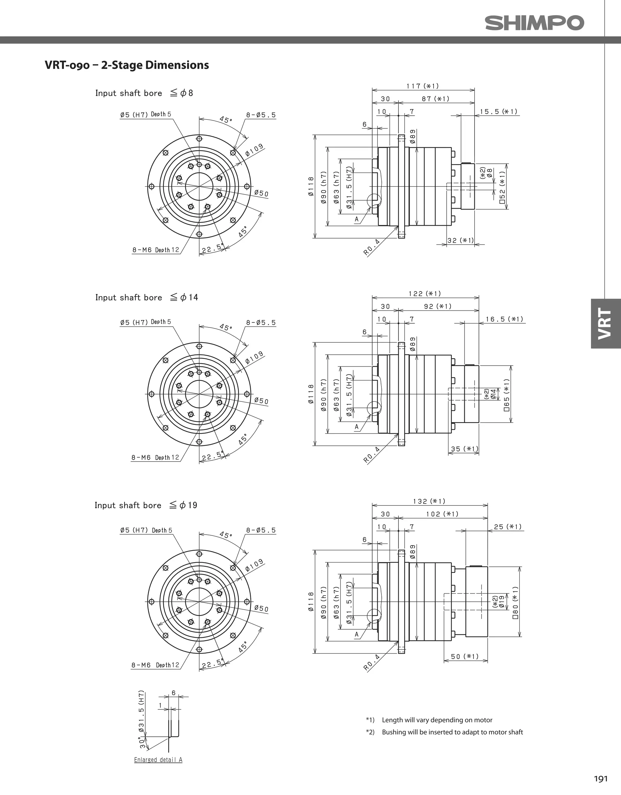


![194
VRT-SERIES Inline shaft
VRT-110 – 1-Stage Specifications
VRT-110 – 2-Stage Specifications
Frame Size 110
Stage 1-Stage
Ratio Unit Note 4 5 7 10
Nominal Output Torque [Nm] *1 120 180 180 120
Maximum Output Torque [Nm] *2 330 330 330 225
Emergency Stop Torque [Nm] *3 625 625 625 500
Nominal Input Speed [rpm] *4 3000
Maximum Input Speed [rpm] *5 6000
No Load Running Torque [Nm] *6 0.77
Permitted Radial Load [N] *7 4700 5000 5600 6200
Permitted Axial Load [N] *8 3200 3400 3800 4200
Maximum Radial Load [N] *9 12000
Maximum Axial Load [N] *10 8800
Moment of Inertia (≤ Ø 14) [kgcm2] -- -- -- -- --
Moment of Inertia (≤ Ø 19) [kgcm2] -- 3.100 2.300 1.500 1.100
Moment of Inertia (≤ Ø 28) [kgcm2] -- 5.100 4.300 3.500 3.100
Moment of Inertia (≤ Ø 38) [kgcm2] -- 13.000 12.000 11.000 11.000
Efficiency [%] *11 95
Torsional Rigidity [Nm/arcmin] *12 31
Maximum Torsional Backlash [Arc-min] -- ≤ 3
Noise Level [dB] *13 ≤ 71
Protection Class -- *14 IP54 (IP65)
Ambient Temperature [°C] -- 0 - 40
Permitted Housing Temperature [°C] -- 90
Weight [kg] *15 7.8
Frame Size 110
Stage 2-Stage
Ratio Unit Note 16 20 25 28
Nominal Output Torque [Nm] *1 180 180 180 180
Maximum Output Torque [Nm] *2 330 330 330 330
Emergency Stop Torque [Nm] *3 625 625 625 625
Nominal Input Speed [rpm] *4 3000
Maximum Input Speed [rpm] *5 6000
No Load Running Torque [Nm] *6 0.17
Permitted Radial Load [N] *7 7100 7600 8200 8500
Permitted Axial Load [N] *8 4800 5200 5500 5700
Maximum Radial Load [N] *9 12000
Maximum Axial Load [N] *10 8800
Moment of Inertia (≤ Ø 14) [kgcm2] -- 1.000 0.800 0.700 0.900
Moment of Inertia (≤ Ø 19) [kgcm2] -- 1.500 1.200 1.200 1.400
Moment of Inertia (≤ Ø 28) [kgcm2] -- 3.400 3.100 3.100 3.300
Moment of Inertia (≤ Ø 38) [kgcm2] -- 11.000 11.000 11.000 11.000
Efficiency [%] *11 90
Torsional Rigidity [Nm/arcmin] *12 31
Maximum Torsional Backlash [Arc-min] -- ≤ 3
Noise Level [dB] *13 ≤ 71
Protection Class -- *14 IP54 (IP65)
Ambient Temperature [°C] -- 0 - 40
Permitted Housing Temperature [°C] -- 90
Weight [kg] *15 8.6](https://image.slidesharecdn.com/shimpohighprecisioncatalog-140807090507-phpapp01/75/Shimpo-high-precision-catalog-196-2048.jpg)
![195
VRT
VRT-110 – 2-Stage Specifications
*1) At nominal input speed, service life is 20,000 hours
*2) The maximum torque when starting or stopping operation
*3) The maximum torque allowed under a stress situation (Permitted 1,000 times during service life)
*4) The average input speed
*5) The maximum intermittent input speed
*6) This is the torque at no load applied on the input shaft. The input speed is 3,000 rpm for VRT 110
*7) At this load and nominal input speed, service life will be 20,000 hours. (The radial load applied to the output side bearing)
*8) At this load and nominal input speed, service life will be 20,000 hours. (The axial load applied to the output flange center)
*9) The maximum radial load that the reducer can accept
*10) The maximum axial load that the reducer can accept
*11) The efficiency at the nominal torque rating
*12) This does not include the lost motion
*13) Contact NIDEC-SHIMPO for the testing conditions and environment
*14) IP65 (wash-down) is available as an option. Contact NIDEC-SHIMPO for more details and our food grade options
*15) The weight may vary slightly between models
Frame Size 110
Stage 2-Stage
Ratio Unit Note 35 40 50 70 100
Nominal Output Torque [Nm] *1 180 180 180 180 120
Maximum Output Torque [Nm] *2 330 330 330 330 225
Emergency Stop Torque [Nm] *3 625 625 625 625 500
Nominal Input Speed [rpm] *4 3000
Maximum Input Speed [rpm] *5 6000
No Load Running Torque [Nm] *6 0.17
Permitted Radial Load [N] *7 9000 9400 10000 11000 12000
Permitted Axial Load [N] *8 6100 6400 6800 7500 8400
Maximum Radial Load [N] *9 12000
Maximum Axial Load [N] *10 8800
Moment of Inertia (≤ Ø 14) [kgcm2] -- 0.700 0.400 0.400 0.400 0.400
Moment of Inertia (≤ Ø 19) [kgcm2] -- 1.100 0.800 0.800 0.800 0.800
Moment of Inertia (≤ Ø 28) [kgcm2] -- 3.100 2.800 2.800 2.700 2.700
Moment of Inertia (≤ Ø 38) [kgcm2] -- 11.000 10.000 10.000 10.000 10.000
Efficiency [%] *11 --
Torsional Rigidity [Nm/arcmin] *12 31
Maximum Torsional Backlash [Arc-min] -- ≤ 3
Noise Level [dB] *13 ≤ 71
Protection Class -- *14 IP54 (IP65)
Ambient Temperature [°C] -- 0 - 40
Permitted Housing Temperature [°C] -- 90
Weight [kg] *15 8.6](https://image.slidesharecdn.com/shimpohighprecisioncatalog-140807090507-phpapp01/75/Shimpo-high-precision-catalog-197-2048.jpg)

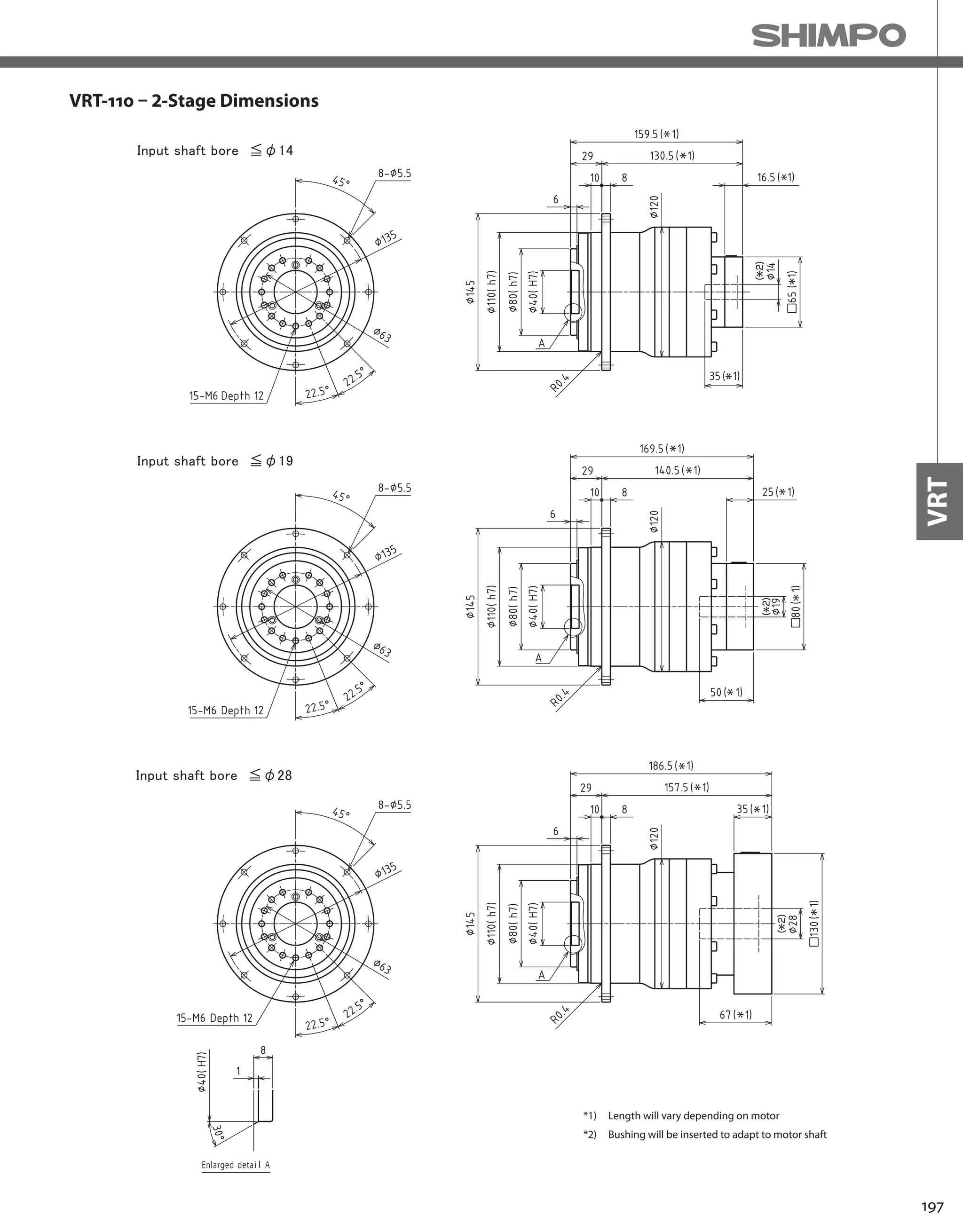


![200
VRT-SERIES Inline shaft
VRT-140 – 1-Stage Specifications
VRT-140 – 2-Stage Specifications
Frame Size 140
Stage 1-Stage
Ratio Unit Note 4 5 7 10
Nominal Output Torque [Nm] *1 240 360 360 240
Maximum Output Torque [Nm] *2 700 700 700 470
Emergency Stop Torque [Nm] *3 1250 1250 1250 1000
Nominal Input Speed [rpm] *4 2000
Maximum Input Speed [rpm] *5 4000
No Load Running Torque [Nm] *13 1.00
Permitted Radial Load [N] *6 8000 8500 9400 10000
Permitted Axial Load [N] *7 5600 6000 6700 7400
Maximum Radial Load [N] *8 19000
Maximum Axial Load [N] *9 14000
Moment of Inertia (≤ Ø 19) [kgcm2] *10 -- -- -- --
Moment of Inertia (≤ Ø 28) [kgcm2] -- 11.000 8.400 5.400 4.100
Moment of Inertia (≤ Ø 38) [kgcm2] -- 19.000 16.000 13.000 12.000
Moment of Inertia (≤ Ø 48) [kgcm2] -- 41.000 38.000 35.000 34.000
Efficiency [%] -- 95
Torsional Rigidity [Nm/arcmin] *11 60
Maximum Torsional Backlash [Arc-min] *12 ≤ 3
Noise Level [dB] -- ≤ 67
Protection Class -- *14 IP54 (IP65)
Ambient Temperature [°C] -- 0 - 40
Permitted Housing Temperature [°C] -- 90
Weight [kg] *15 15
Frame Size 140
Stage 2-Stage
Ratio Unit Note 16 20 25 28
Nominal Output Torque [Nm] *1 360 360 360 360
Maximum Output Torque [Nm] *2 700 700 700 700
Emergency Stop Torque [Nm] *3 1250 1250 1250 1250
Nominal Input Speed [rpm] *4 2000
Maximum Input Speed [rpm] *5 4000
No Load Running Torque [Nm] *13 0.54
Permitted Radial Load [N] *6 12000 13000 14000 14000
Permitted Axial Load [N] *7 8500 9100 9800 10000
Maximum Radial Load [N] *8 19000
Maximum Axial Load [N] *9 14000
Moment of Inertia (≤ Ø 19) [kgcm2] *10 3.800 2.600 2.500 3.400
Moment of Inertia (≤ Ø 28) [kgcm2] -- 5.800 4.600 4.500 5.400
Moment of Inertia (≤ Ø 38) [kgcm2] -- 13.000 12.000 12.000 13.000
Moment of Inertia (≤ Ø 48) [kgcm2] -- 35.000 34.000 34.000 35.000
Efficiency [%] -- 90
Torsional Rigidity [Nm/arcmin] *11 60
Maximum Torsional Backlash [Arc-min] *12 ≤ 3
Noise Level [dB] -- ≤ 67
Protection Class -- *14 IP54 (IP65)
Ambient Temperature [°C] -- 0 - 40
Permitted Housing Temperature [°C] -- 90
Weight [kg] *15 17](https://image.slidesharecdn.com/shimpohighprecisioncatalog-140807090507-phpapp01/75/Shimpo-high-precision-catalog-202-2048.jpg)
![201
VRT
VRT-140 – 2-Stage Specifications
*1) At nominal input speed, service life is 20,000 hours
*2) The maximum torque when starting or stopping operation
*3) The maximum torque allowed under a stress situation (Permitted 1,000 times during service life)
*4) The average input speed
*5) The maximum intermittent input speed
*6) This is the torque at no load applied on the input shaft. The input speed is 2,000 rpm for VRT140
*7) At this load and nominal input speed, service life will be 20,000 hours. (The radial load applied to the output side bearing)
*8) At this load and nominal input speed, service life will be 20,000 hours. (The axial load applied to the output flange center)
*9) The maximum radial load that the reducer can accept
*10) The maximum axial load that the reducer can accept
*11) The efficiency at the nominal torque rating
*12) This does not include the lost motion
*13) Contact NIDEC-SHIMPO for the testing conditions and environment
*14) IP65 (wash-down) is available as an option. Contact NIDEC-SHIMPO for more details and our food grade options
*15) The weight may vary slightly between models
Frame Size 140
Stage 2-Stage
Ratio Unit Note 35 40 50 70 100
Nominal Output Torque [Nm] *1 360 360 360 360 240
Maximum Output Torque [Nm] *2 700 700 700 700 470
Emergency Stop Torque [Nm] *3 1250 1250 1250 1250 1000
Nominal Input Speed [rpm] *4 2000
Maximum Input Speed [rpm] *5 4000
No Load Running Torque [Nm] *13 0.54
Permitted Radial Load [N] *6 15000 16000 17000 19000 19000
Permitted Axial Load [N] *7 11000 11000 12000 13000 14000
Maximum Radial Load [N] *8 19000
Maximum Axial Load [N] *9 14000
Moment of Inertia (≤ Ø 19) [kgcm2] *10 2.400 1.200 1.100 1.100 1.100
Moment of Inertia (≤ Ø 28) [kgcm2] -- 4.400 3.100 3.100 3.100 3.100
Moment of Inertia (≤ Ø 38) [kgcm2] -- 12.000 11.000 11.000 11.000 11.000
Moment of Inertia (≤ Ø 48) [kgcm2] -- 34.000 33.000 33.000 33.000 33.000
Efficiency [%] -- 90
Torsional Rigidity [Nm/arcmin] *11 60
Maximum Torsional Backlash [Arc-min] *12 ≤ 3
Noise Level [dB] -- ≤ 67
Protection Class -- *14 IP54 (IP65)
Ambient Temperature [°C] -- 0 - 40
Permitted Housing Temperature [°C] -- 90
Weight [kg] *15 17](https://image.slidesharecdn.com/shimpohighprecisioncatalog-140807090507-phpapp01/75/Shimpo-high-precision-catalog-203-2048.jpg)


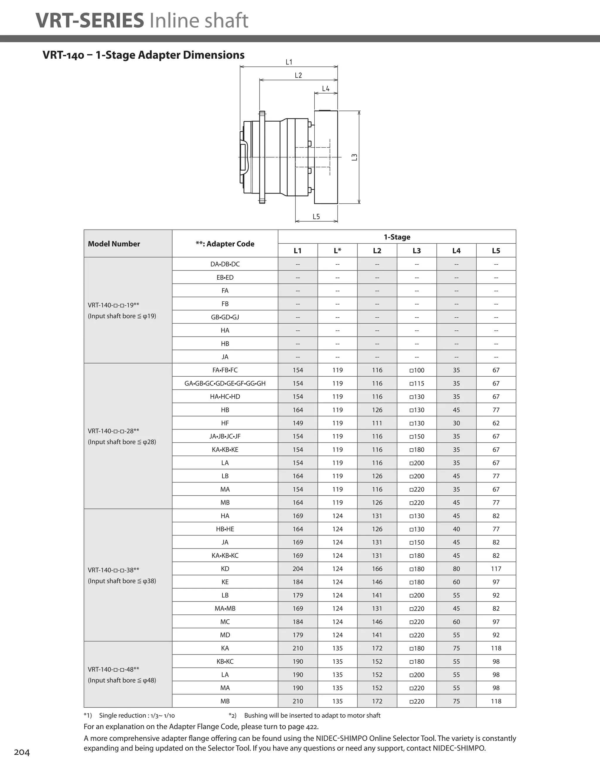

![206
VRT-SERIES Inline shaft
VRT-200 – 1-Stage Specifications
VRT-200 – 2-Stage Specifications
Frame Size 200
Stage 1-Stage
Ratio Unit Note 4 5 7 10
Nominal Output Torque [Nm] *1 750 750 750 500
Maximum Output Torque [Nm] *2 1400 1400 1400 970
Emergency Stop Torque [Nm] *3 2750 2750 2750 2200
Nominal Input Speed [rpm] *4 1500
Maximum Input Speed [rpm] *5 3000
No Load Running Torque [Nm] *13 1.9
Permitted Radial Load [N] *6 18000 19000 21000 23000
Permitted Axial Load [N] *7 12000 13000 14000 16000
Maximum Radial Load [N] *8 40000
Maximum Axial Load [N] *9 30000
Moment of Inertia (≤ Ø 28) [kgcm2] *10 -- -- -- --
Moment of Inertia (≤ Ø 38) [kgcm2] -- 54.000 39.000 25.000 18.000
Moment of Inertia (≤ Ø 48) [kgcm2] -- 76.000 61.000 47.000 40.000
Moment of Inertia (≤ Ø 65) [kgcm2] -- 140.000 120.000 110.000 100.000
Efficiency [%] -- 95
Torsional Rigidity [Nm/arcmin] *11 175
Maximum Torsional Backlash [Arc-min] *12 ≤ 3
Noise Level [dB] -- ≤ 67
Protection Class -- *14 IP54 (IP65)
Ambient Temperature [°C] -- 0 - 40
Permitted Housing Temperature [°C] -- 90
Weight [kg] *15 42
Frame Size 200
Stage 2-Stage
Ratio Unit Note 16 20 25 28
Nominal Output Torque [Nm] *1 750 750 750 750
Maximum Output Torque [Nm] *2 1400 1400 1400 1400
Emergency Stop Torque [Nm] *3 2750 2750 2750 2750
Nominal Input Speed [rpm] *4 1500
Maximum Input Speed [rpm] *5 3000
No Load Running Torque [Nm] *13 1.3
Permitted Radial Load [N] *6 27000 28000 30000 31000
Permitted Axial Load [N] *7 18000 19000 21000 21000
Maximum Radial Load [N] *8 40000
Maximum Axial Load [N] *9 30000
Moment of Inertia (≤ Ø 28) [kgcm2] *10 13.000 9.400 8.800 11.000
Moment of Inertia (≤ Ø 38) [kgcm2] -- 21.000 17.000 16.000 19.000
Moment of Inertia (≤ Ø 48) [kgcm2] -- 43.000 39.000 38.000 41.000
Moment of Inertia (≤ Ø 65) [kgcm2] -- -- -- -- --
Efficiency [%] -- 90
Torsional Rigidity [Nm/arcmin] *11 175
Maximum Torsional Backlash [Arc-min] *12 ≤ 3
Noise Level [dB] -- ≤ 67
Protection Class -- *14 IP54 (IP65)
Ambient Temperature [°C] -- 0 - 40
Permitted Housing Temperature [°C] -- 90
Weight [kg] *15 43](https://image.slidesharecdn.com/shimpohighprecisioncatalog-140807090507-phpapp01/75/Shimpo-high-precision-catalog-208-2048.jpg)
![207
VRT
VRT-200 – 2-Stage Specifications
*1) At nominal input speed, service life is 20,000 hours
*2) The maximum torque when starting or stopping operation
*3) The maximum torque allowed under a stress situation (Permitted 1,000 times during service life)
*4) The average input speed
*5) The maximum intermittent input speed
*6) This is the torque at no load applied on the input shaft. The input speed is 1,500 rpm for VRT 200
*7) At this load and nominal input speed, service life will be 20,000 hours. (The radial load applied to the output side bearing)
*8) At this load and nominal input speed, service life will be 20,000 hours. (The axial load applied to the output flange center)
*9) The maximum radial load that the reducer can accept
*10) The maximum axial load that the reducer can accept
*11) The efficiency at the nominal torque rating
*12) This does not include the lost motion
*13) Contact NIDEC-SHIMPO for the testing conditions and environment
*14) IP65 (wash-down) is available as an option. Contact NIDEC-SHIMPO for more details and our food grade options
*15) The weight may vary slightly between models
Frame Size 200
Stage 2-Stage
Ratio Unit Note 35 40 50 70 100
Nominal Output Torque [Nm] *1 750 750 750 750 500
Maximum Output Torque [Nm] *2 1400 1400 1400 1400 970
Emergency Stop Torque [Nm] *3 2750 2750 2750 2750 2200
Nominal Input Speed [rpm] *4 1500
Maximum Input Speed [rpm] *5 3000
No Load Running Torque [Nm] *13 1.3
Permitted Radial Load [N] *6 34000 35000 37000 40000 40000
Permitted Axial Load [N] *7 23000 24000 25000 28000 30000
Maximum Radial Load [N] *8 40000
Maximum Axial Load [N] *9 30000
Moment of Inertia (≤ Ø 28) [kgcm2] *10 8.200 4.400 4.200 4.100 4.000
Moment of Inertia (≤ Ø 38) [kgcm2] -- 16.000 12.000 12.000 12.000 12.000
Moment of Inertia (≤ Ø 48) [kgcm2] -- 38.000 34.000 34.000 34.000 34.000
Moment of Inertia (≤ Ø 65) [kgcm2] -- -- -- -- -- --
Efficiency [%] -- 90
Torsional Rigidity [Nm/arcmin] *11 175
Maximum Torsional Backlash [Arc-min] *12 ≤ 3
Noise Level [dB] -- ≤ 67
Protection Class -- *14 IP54 (IP65)
Ambient Temperature [°C] -- 0 - 40
Permitted Housing Temperature [°C] -- 90
Weight [kg] *15 43](https://image.slidesharecdn.com/shimpohighprecisioncatalog-140807090507-phpapp01/75/Shimpo-high-precision-catalog-209-2048.jpg)
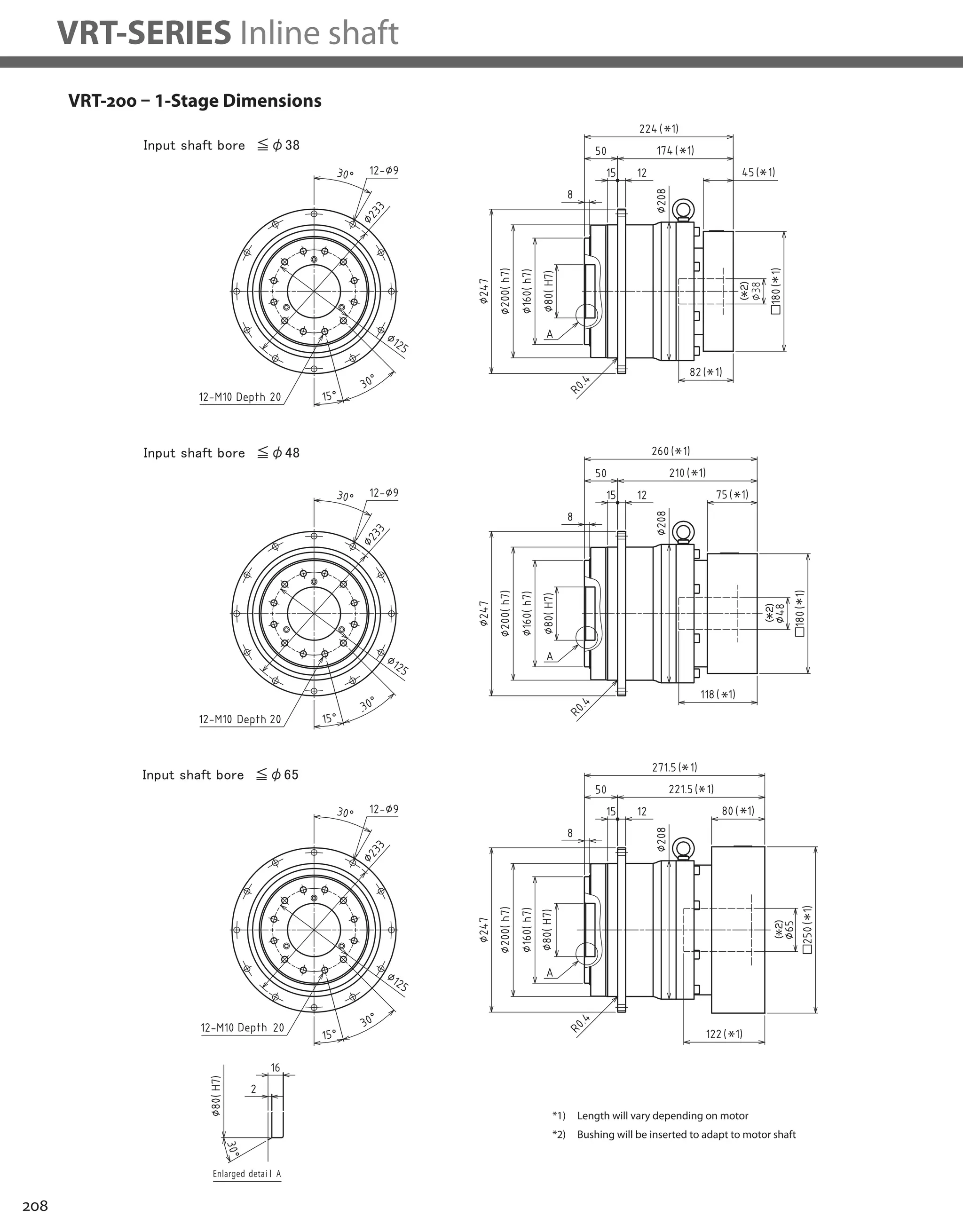


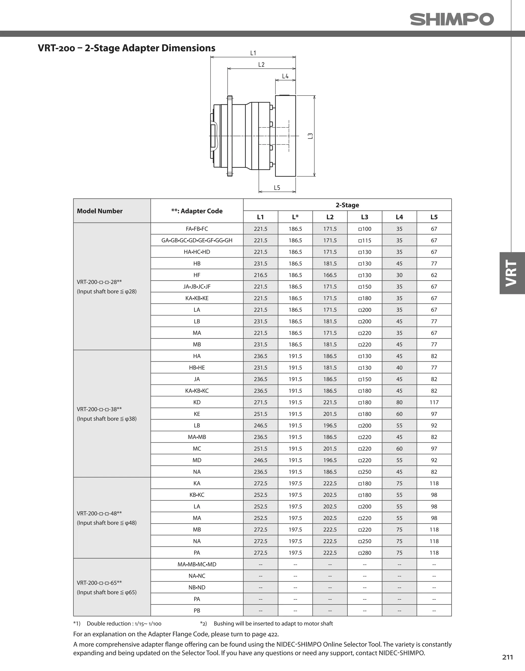
![212
VRT-SERIES Inline shaft
VRT-255 – 1-Stage Specifications
VRT-255 – 2-Stage Specifications
Frame Size 255
Stage 1-Stage
Ratio Unit Note 4 5 7 10
Nominal Output Torque [Nm] *1 2400 2400 2400 1600
Maximum Output Torque [Nm] *2 3700 3700 3700 2600
Emergency Stop Torque [Nm] *3 8000 8000 8000 6000
Nominal Input Speed [rpm] *4 1000
Maximum Input Speed [rpm] *5 2000
No Load Running Torque [Nm] *13 2.5
Permitted Radial Load [N] *6 31000 33000 36000 40000
Permitted Axial Load [N] *7 22000 24000 26000 29000
Maximum Radial Load [N] *8 64000
Maximum Axial Load [N] *9 48000
Moment of Inertia (≤ Ø 48) [kgcm2] *10 -- -- -- --
Moment of Inertia (≤ Ø 65) [kgcm2] -- 200 170 130 110
Efficiency [%] -- 95
Torsional Rigidity [Nm/arcmin] *11 550
Maximum Torsional Backlash [Arc-min] *12 ≤ 3
Noise Level [dB] -- ≤ 62
Protection Class -- *14 IP54 (IP65)
Ambient Temperature [°C] -- 0 - 40
Permitted Housing Temperature [°C] -- 90
Weight [kg] *15 84
Frame Size 255
Stage 2-Stage
Ratio Unit Note 16 20 25 28
Nominal Output Torque [Nm] *1 2400 2400 2400 2400
Maximum Output Torque [Nm] *2 3700 3700 3700 3700
Emergency Stop Torque [Nm] *3 8000 8000 8000 8000
Nominal Input Speed [rpm] *4 1000
Maximum Input Speed [rpm] *5 2000
No Load Running Torque [Nm] *13 1.0
Permitted Radial Load [N] *6 46000 49000 53000 55000
Permitted Axial Load [N] *7 34000 36000 38000 40000
Maximum Radial Load [N] *8 64000
Maximum Axial Load [N] *9 48000
Moment of Inertia (≤ Ø 48) [kgcm2] *10 64.0 53.0 51.0 59.0
Moment of Inertia (≤ Ø 65) [kgcm2] -- -- -- -- --
Efficiency [%] -- 90
Torsional Rigidity [Nm/arcmin] *11 550
Maximum Torsional Backlash [Arc-min] *12 ≤ 3
Noise Level [dB] -- ≤ 62
Protection Class -- *14 IP54 (IP65)
Ambient Temperature [°C] -- 0 - 40
Permitted Housing Temperature [°C] -- 90
Weight [kg] *15 89](https://image.slidesharecdn.com/shimpohighprecisioncatalog-140807090507-phpapp01/75/Shimpo-high-precision-catalog-214-2048.jpg)
![213
VRT
VRT-255 – 2-Stage Specifications
*1) At nominal input speed, service life is 20,000 hours
*2) The maximum torque when starting or stopping operation
*3) The maximum torque allowed under a stress situation (Permitted 1,000 times during service life)
*4) The average input speed
*5) The maximum intermittent input speed
*6) This is the torque at no load applied on the input shaft. The input speed is 1,000 rpm for 255
*7) At this load and nominal input speed, service life will be 20,000 hours. (The radial load applied to the output side bearing)
*8) At this load and nominal input speed, service life will be 20,000 hours. (The axial load applied to the output flange center)
*9) The maximum radial load that the reducer can accept
*10) The maximum axial load that the reducer can accept
*11) The efficiency at the nominal torque rating
*12) This does not include the lost motion
*13) Contact NIDEC-SHIMPO for the testing conditions and environment
*14) IP65 (wash-down) is available as an option. Contact NIDEC-SHIMPO for more details and our food grade options
*15) The weight may vary slightly between models
Frame Size 255
Stage 2-Stage
Ratio Unit Note 35 40 50 70 100
Nominal Output Torque [Nm] *1 2400 2400 2400 2400 1600
Maximum Output Torque [Nm] *2 3700 3700 3700 3700 1800
Emergency Stop Torque [Nm] *3 8000 8000 8000 8000 6000
Nominal Input Speed [rpm] *4 1000
Maximum Input Speed [rpm] *5 2000
No Load Running Torque [Nm] *13 1.0
Permitted Radial Load [N] *6 59000 61000 64000 64000 64000
Permitted Axial Load [N] *7 42000 44000 47000 48000 48000
Maximum Radial Load [N] *8 64000
Maximum Axial Load [N] *9 48000
Moment of Inertia (≤ Ø 48) [kgcm2] *10 50.0 38.0 38.0 37.0 37.0
Moment of Inertia (≤ Ø 65) [kgcm2] -- -- -- -- -- --
Efficiency [%] -- 90
Torsional Rigidity [Nm/arcmin] *11 550
Maximum Torsional Backlash [Arc-min] *12 ≤ 3
Noise Level [dB] -- ≤ 62
Protection Class -- *14 IP54 (IP65)
Ambient Temperature [°C] -- 0 - 40
Permitted Housing Temperature [°C] -- 90
Weight [kg] *15 89](https://image.slidesharecdn.com/shimpohighprecisioncatalog-140807090507-phpapp01/75/Shimpo-high-precision-catalog-215-2048.jpg)

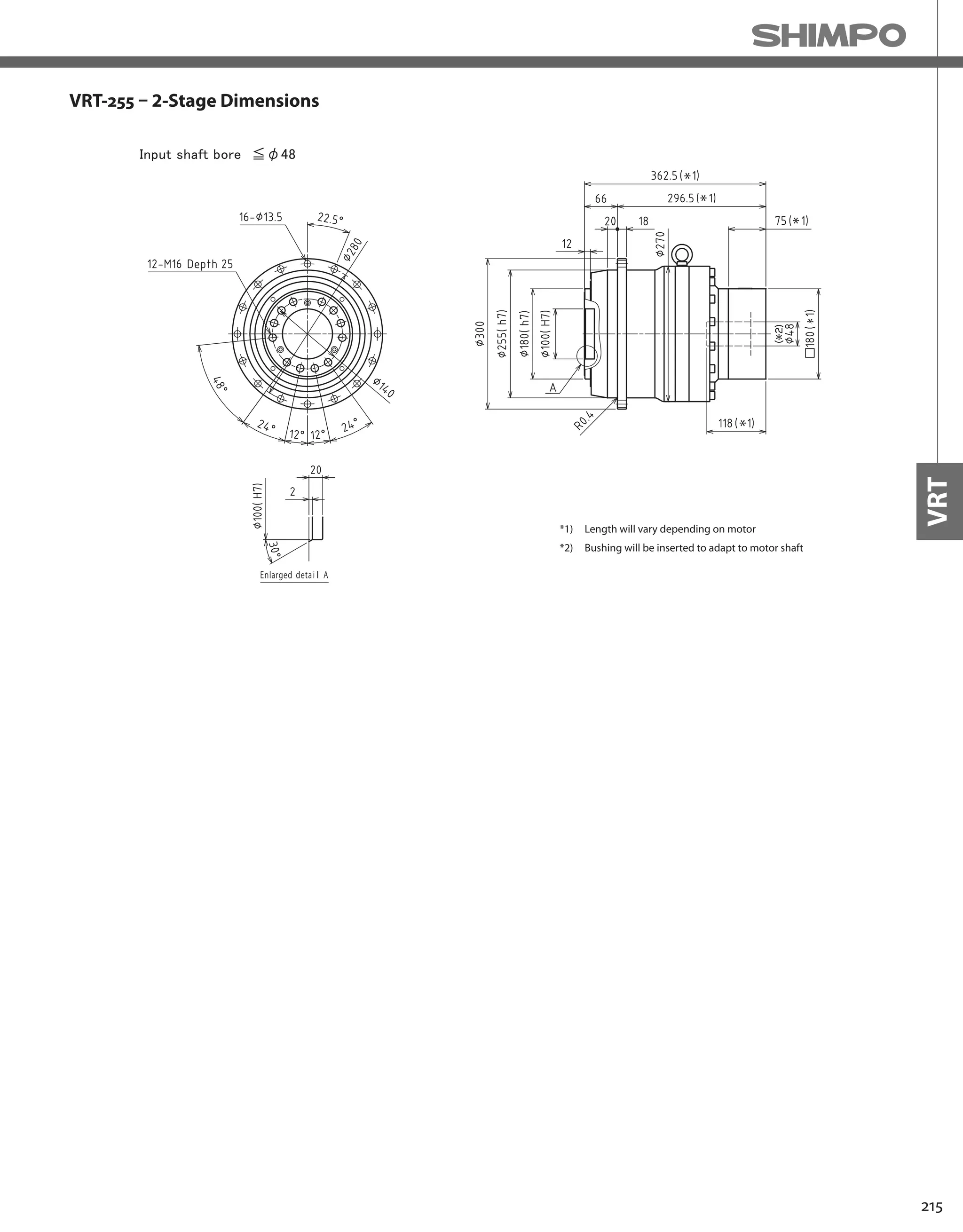
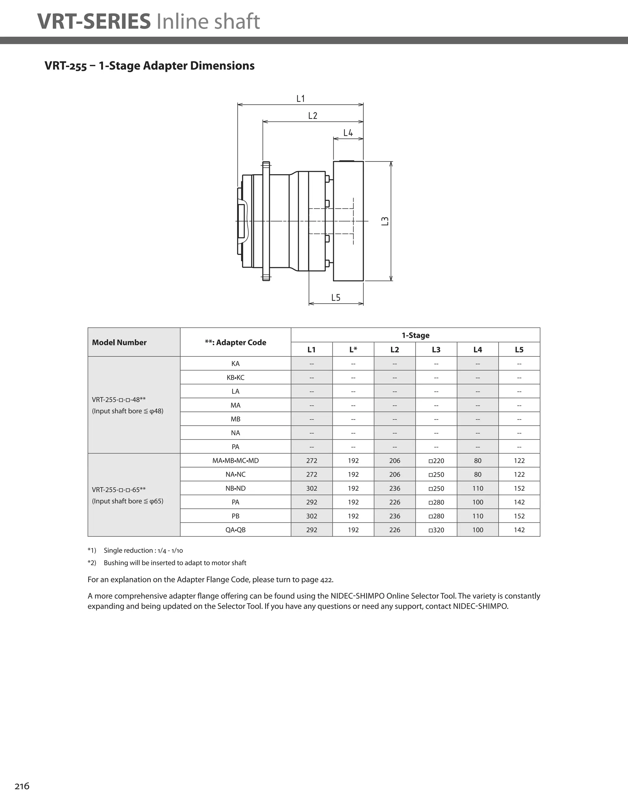

![218
VRT-SERIES Inline shaft
VRT-285 – 1-Stage Specifications
VRT-285 – 2-Stage Specifications
Frame Size 285
Stage 1-Stage
Ratio Unit Note 4 5 7 10
Nominal Output Torque [Nm] *1 3300 3300 3300 2200
Maximum Output Torque [Nm] *2 5300 5300 5300 3700
Emergency Stop Torque [Nm] *3 12000 12000 12000 10000
Nominal Input Speed [rpm] *4 1000
Maximum Input Speed [rpm] *5 2000
No Load Running Torque [Nm] *13 2.7
Permitted Radial Load [N] *6 40000 42000 47000 52000
Permitted Axial Load [N] *7 34000 36000 40000 45000
Maximum Radial Load [N] *8 86000
Maximum Axial Load [N] *9 64000
Moment of Inertia (≤ Ø 48) [kgcm2] *10 -- -- -- --
Moment of Inertia (≤ Ø 65) [kgcm2] -- 250 200 140 120
Efficiency [%] -- 95
Torsional Rigidity [Nm/arcmin] *11 850
Maximum Torsional Backlash [Arc-min] *12 ≤ 3
Noise Level [dB] -- ≤ 63
Protection Class -- *14 IP54 (IP65)
Ambient Temperature [°C] -- 0 - 40
Permitted Housing Temperature [°C] -- 90
Weight [kg] *15 110
Frame Size 285
Stage 2-Stage
Ratio Unit Note 16 20 25 28
Nominal Output Torque [Nm] *1 2750 3300 3300 3300
Maximum Output Torque [Nm] *2 5300 5300 5300 5300
Emergency Stop Torque [Nm] *3 12000 12000 12000 12000
Nominal Input Speed [rpm] *4 1000
Maximum Input Speed [rpm] *5 2000
No Load Running Torque [Nm] *13 0.6
Permitted Radial Load [N] *6 60000 64000 69000 71000
Permitted Axial Load [N] *7 51000 55000 59000 61000
Maximum Radial Load [N] *8 86000
Maximum Axial Load [N] *9 64000
Moment of Inertia (≤ Ø 48) [kgcm2] *10 48.0 42.0 41.0 42.0
Moment of Inertia (≤ Ø 65) [kgcm2] -- -- -- -- --
Efficiency [%] -- 90
Torsional Rigidity [Nm/arcmin] *11 850
Maximum Torsional Backlash [Arc-min] *12 ≤ 3
Noise Level [dB] -- ≤ 63
Protection Class -- *14 IP54 (IP65)
Ambient Temperature [°C] -- 0 - 40
Permitted Housing Temperature [°C] -- 90
Weight [kg] *15 120](https://image.slidesharecdn.com/shimpohighprecisioncatalog-140807090507-phpapp01/75/Shimpo-high-precision-catalog-220-2048.jpg)
![219
VRT
VRT-285 – 2-Stage Specifications
*1) At nominal input speed, service life is 20,000 hours
*2) The maximum torque when starting or stopping operation
*3) The maximum torque allowed under a stress situation (Permitted 1,000 times during service life)
*4) The average input speed
*5) The maximum intermittent input speed
*6) This is the torque at no load applied on the input shaft. The input speed is 1,000 rpm for VRT285
*7) At this load and nominal input speed, service life will be 20,000 hours. (The radial load applied to the output side bearing)
*8) At this load and nominal input speed, service life will be 20,000 hours. (The axial load applied to the output flange center)
*9) The maximum radial load that the reducer can accept
*10) The maximum axial load that the reducer can accept
*11) The efficiency at the nominal torque rating
*12) This does not include the lost motion
*13) Contact NIDEC-SHIMPO for the testing conditions and environment
*14) IP65 (wash-down) is available as an option. Contact NIDEC-SHIMPO for more details and our food grade options
*15) The weight may vary slightly between models
Frame Size 285
Stage 2-Stage
Ratio Unit Note 35 40 50 70 100
Nominal Output Torque [Nm] *1 3300 3300 3300 3300 2200
Maximum Output Torque [Nm] *2 5300 5300 5300 5300 2500
Emergency Stop Torque [Nm] *3 12000 12000 12000 12000 10000
Nominal Input Speed [rpm] *4 1000
Maximum Input Speed [rpm] *5 2000
No Load Running Torque [Nm] *13 0.6
Permitted Radial Load [N] *6 76000 79000 85000 86000 86000
Permitted Axial Load [N] *7 64000 64000 64000 64000 64000
Maximum Radial Load [N] *8 86000
Maximum Axial Load [N] *9 64000
Moment of Inertia (≤ Ø 48) [kgcm2] *10 39.0 36.0 35.0 35.0 35.0
Moment of Inertia (≤ Ø 65) [kgcm2] -- -- -- -- -- --
Efficiency [%] -- 90
Torsional Rigidity [Nm/arcmin] *11 850
Maximum Torsional Backlash [Arc-min] *12 ≤ 3
Noise Level [dB] -- ≤ 63
Protection Class -- *14 IP54 (IP65)
Ambient Temperature [°C] -- 0 - 40
Permitted Housing Temperature [°C] -- 90
Weight [kg] *15 120](https://image.slidesharecdn.com/shimpohighprecisioncatalog-140807090507-phpapp01/75/Shimpo-high-precision-catalog-221-2048.jpg)


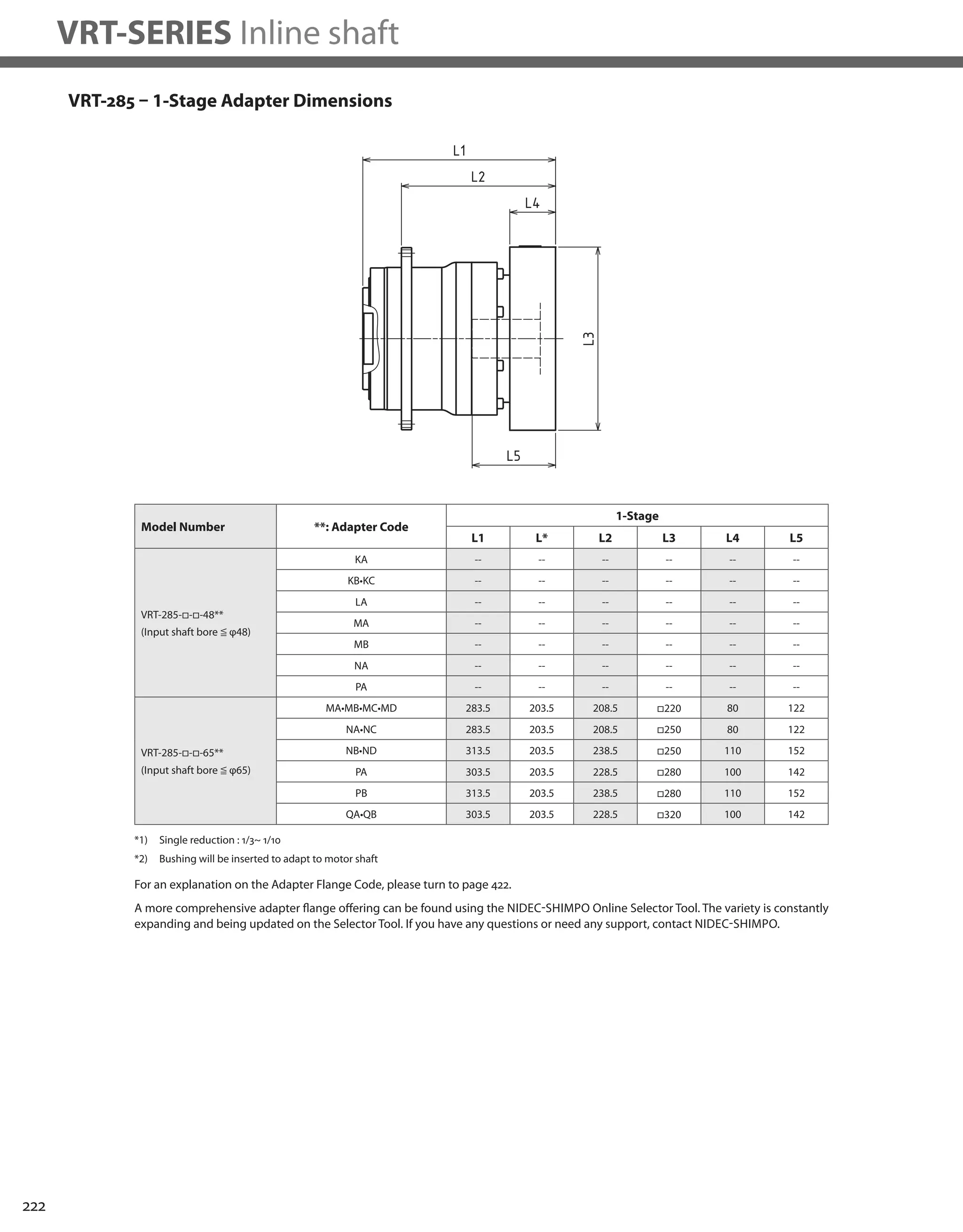


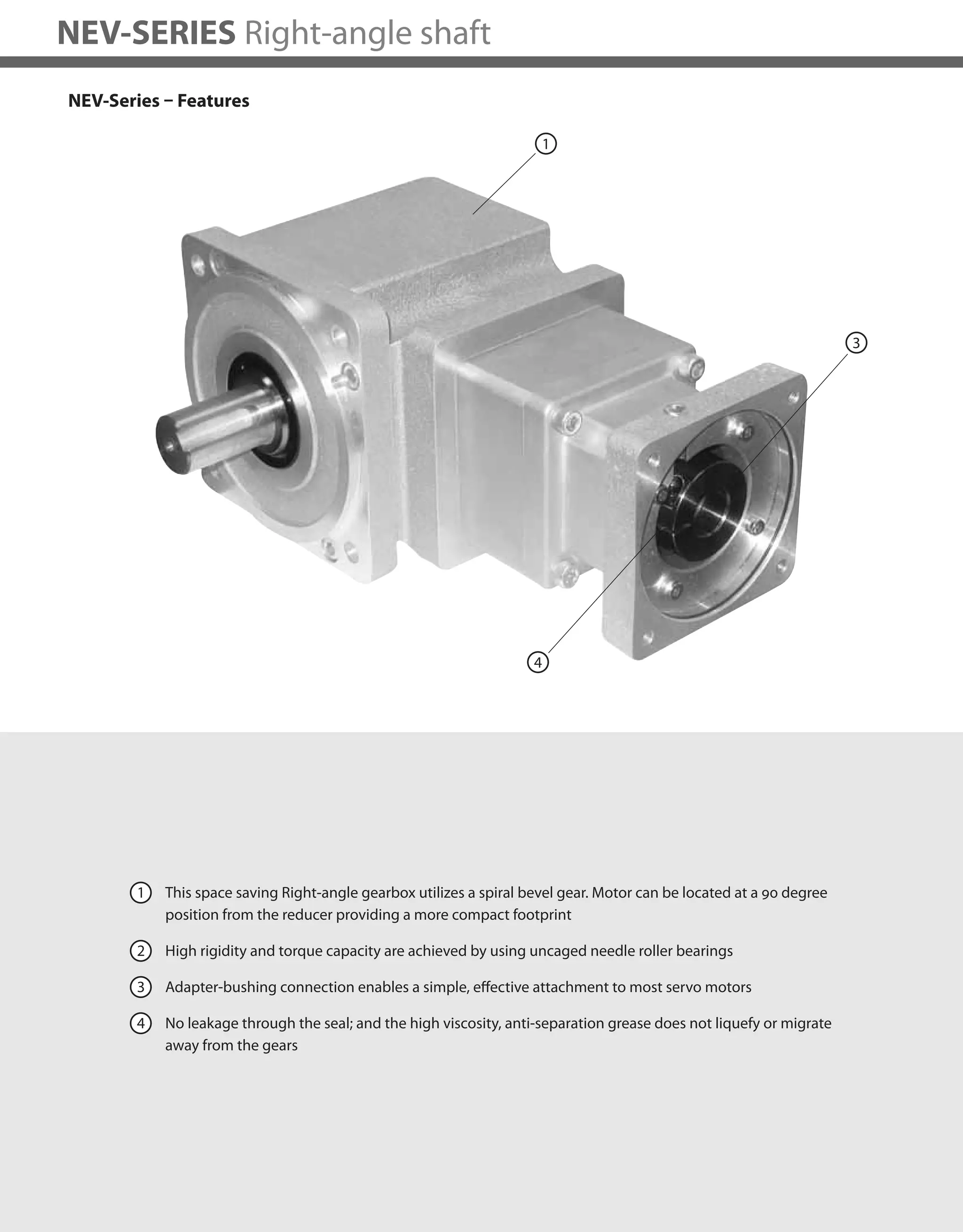
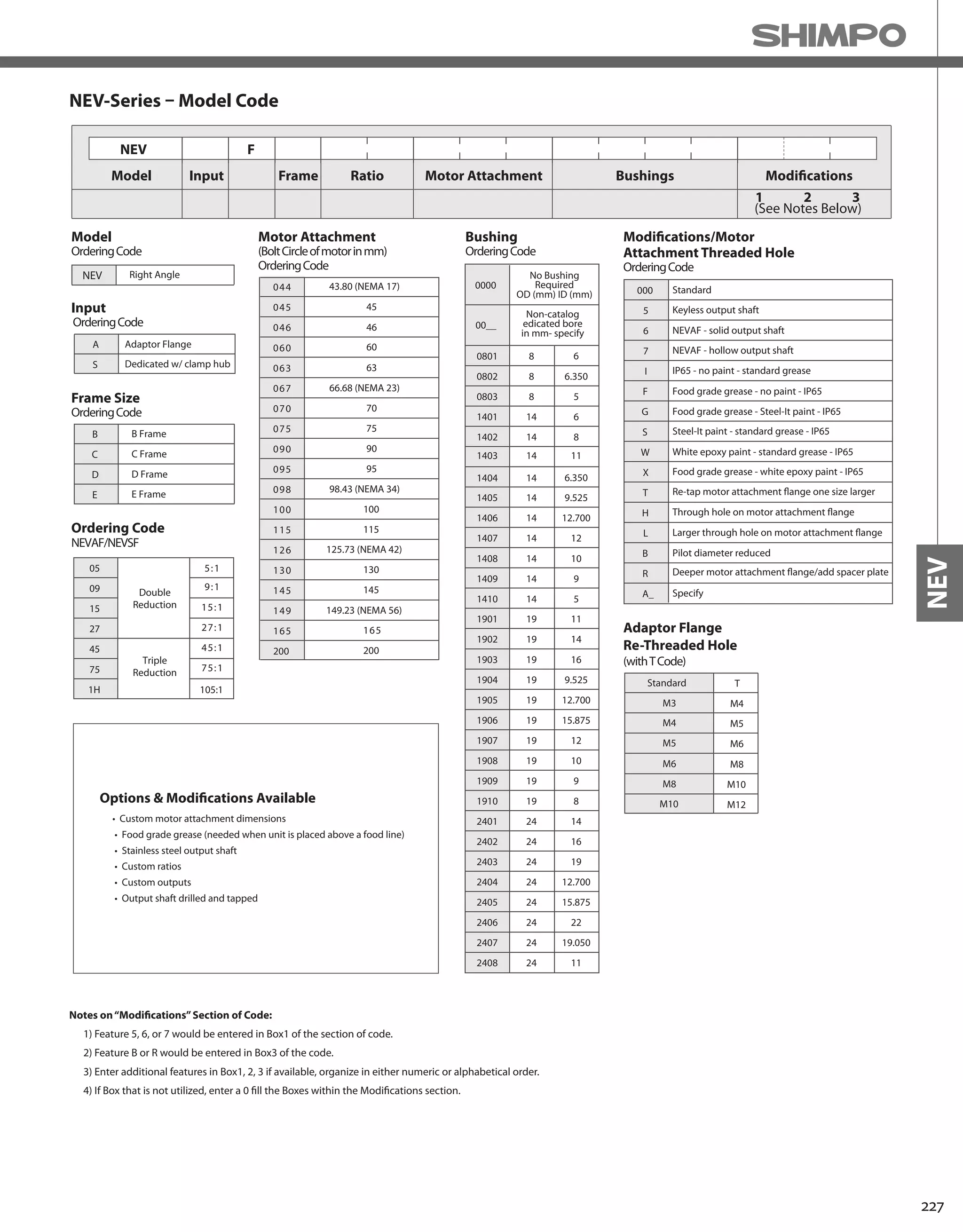
![228
NEV-SERIES Right-angle shaft
NEV B-Frame – 2-Stage Specifications
Frame Size B (78mm)
Stage 2-Stage
Ratio Units Note 5 9 15 27
Nominal Output Torque [Nm] -- 6 6 10 10
Maximum Acceleration Torque [Nm] -- 20 20 30 30
Emergency Stop Torque [Nm] -- 35 40 50 50
Nominal Input Speed [rpm] -- 3000
Maximum Input Speed [rpm] -- 6000
No Load Running Torque [Nm] -- 0.18
Permitted Radial Load [N] -- 1000 1200 1500 1800
Permitted Axial Load [N] -- 500 600 750 900
Moment of Inertia (≤Ø 8) [kgcm2] -- -- -- -- --
Moment of Inertia (≤ Ø14) [kgcm2] -- 0.275 0.110 0.059 0.146
Efficiency [%] -- 85
Torsional Rigidity [Nm/arcmin] -- 0.4
Maximum Torsional Backlash [Arc-min] -- ≤ 30
Noise Level [dB] -- ≤ 73
Protection Class -- -- IP65
Ambient Temperature [°C] -- 0-40
Permitted Housing Temperature [°C] -- 90
Weight (Solid Output Shaft) [kg] -- 3.8
Weight (Hollow Output Shaft) [kg] -- 3.6
NEV B-Frame, 2-Stage Dimensions, Solid / Hollow Output Shaft Type – Ratios: 5:1, 9:1, 15:1, 27:1
Adapter Unit
Bolt Circle
LC
Pilot
LH
Square
LD
Tapping Bolt
LJ
Depth
Y
Length Plug
LK
Flange Depth
L CL LF LG ML
B1
mm 45 30 42 M3x0.5 8 168.5 129.5 10 6 5 32
in 1.772 1.181 1.65 -- 0.31 6.634 5.098 0.39 0.24 0.20 1.26
B2
mm 46 30 42 M4X0.7 10 168.5 129.5 10 6 5 32
in 1.811 1.181 1.65 -- 0.39 6.634 5.098 0.39 0.24 0.20 1.26
B8
mm 46 30 42 M4X0.7 10 171.5 132.5 13 6 8 35
in 1.811 1.181 1.65 -- 0.39 6.752 5.217 0.51 0.24 0.31 1.38
B4
mm 60 50 60 M4X0.7 10 168.5 129.5 10 4 5 32
in 2.362 1.969 2.36 -- 0.39 6.634 5.098 0.39 0.16 0.20 1.26
B4
mm 70 50 60 M4X0.7 10 168.5 129.5 10 4 5 32
in 2.756 1.969 2.36 -- 0.39 6.634 5.098 0.39 0.16 0.20 1.26
B9
mm 70 50 60 M5X0.8 20 173.5 134.5 15 9 10 37
in 2.756 1.969 2.36 -- 0.79 6.831 5.295 0.59 0.35 0.39 1.46
B5 mm 66.68 38.100 58 M4X0.7 10 168.5 129.5 10 4 5 32
(NEMA23) in 2.625 1.500 2.28 -- 0.39 6.634 5.098 0.39 0.16 0.20 1.26
B5+Spacer mm 66.68 38.100 60 M5X0.8 -- 176.5 137.5 18 3 13 40
(NEMA23) in 2.625 1.500 2.36 -- -- 6.949 5.413 0.71 0.12 0.51 1.57
B6
mm 90 70 80 M5X0.8 12 168.5 129.5 10 4 5 32
in 3.543 2.756 3.15 -- 0.47 6.634 5.098 0.39 0.16 0.20 1.26
B7 mm 43.80 22 42 2-3.3 dia. -- 170.5 131.5 12 4 7 34
(NEMA17) in 1.724 0.866 1.65 2-0.13 dia. -- 6.713 5.177 0.47 0.16 0.28 1.34
B10
mm 63 40 58 M4X0.7 10 168.5 129.5 10 4 5 32
in 2.480 1.575 2.28 -- 0.39 6.634 5.098 0.39 0.16 0.20 1.26](https://image.slidesharecdn.com/shimpohighprecisioncatalog-140807090507-phpapp01/75/Shimpo-high-precision-catalog-230-2048.jpg)

![230
NEV-SERIES Right-angle shaft
NEV B-Frame – 3-Stage Specifications
Frame Size B (78mm)
Stage 3-Stage
Ratio Units Note 45 75 105
Nominal Output Torque [Nm] -- 10 15 15
Maximum Acceleration Torque [Nm] -- 30 30 30
Emergency Stop Torque [Nm] -- 50 50 50
Nominal Input Speed [rpm] -- 3000
Maximum Input Speed [rpm] -- 6000
No Load Running Torque [Nm] -- 0.109
Permitted Radial Load [N] -- 1800 1800 1800
Permitted Axial Load [N] -- 900 900 900
Moment of Inertia (≤Ø 8) [kgcm2] -- 0.091 0.083 0.078
Moment of Inertia (≤ Ø14) [kgcm2] -- -- -- --
Efficiency [%] -- 80
Torsional Rigidity [Nm/arcmin] -- 0.4
Maximum Torsional Backlash [Arc-min] -- ≤ 30
Noise Level [dB] -- ≤ 63
Protection Class -- -- IP65
Ambient Temperature [°C] -- 0-40
Permitted Housing Temperature [°C] -- 90
Weight (Solid Output Shaft) [kg] -- 3.9
Weight (Hollow Output Shaft) [kg] -- 3.7
NEV B-Frame, 3-Stage Dimensions, Solid / Hollow Output Shaft Type – Ratios: 45:1, 75:1, 105:1
Adapter Unit
Bolt Circle
LC
Pilot
LH
Square
LD
Tapping Bolt
LJ
Depth
Y
Length Plug
LK
Flange Depth
L CL LF LG ML
B1
mm 45 30 42 M3x0.5 8 174 135 10 6 5 32
in 1.772 1.181 1.65 -- 0.31 6.850 5.315 0.39 0.24 0.20 1.26
B2
mm 46 30 42 M4X0.7 10 174 135 10 6 5 32
in 1.811 1.181 1.65 -- 0.39 6.850 5.315 0.39 0.24 0.20 1.26
B8
mm 46 30 42 M4X0.7 10 177 138 13 6 8 35
in 1.811 1.181 1.65 -- 0.39 6.969 5.433 0.51 0.24 0.31 1.38
B4
mm 60 50 60 M4X0.7 10 174 135 10 4 5 32
in 2.362 1.969 2.36 -- 0.39 6.850 5.315 0.39 0.16 0.20 1.26
B4
mm 70 50 60 M4X0.7 10 174 135 10 4 5 32
in 2.756 1.969 2.36 -- 0.39 6.850 5.315 0.39 0.16 0.20 1.26
B9
mm 70 50 60 M5X0.8 20 179 140 15 9 10 37
in 2.756 1.969 2.36 -- 0.79 7.047 5.512 0.59 0.35 0.39 1.46
B5 mm 66.68 38.100 58 M4X0.7 10 174 135 10 4 5 32
(NEMA23) in 2.625 1.500 2.28 -- 0.39 6.850 5.315 0.39 0.16 0.20 1.26
B5+Spacer mm 66.68 38.100 60 M5X0.8 12 182 143 18 3 13 40
(NEMA23) in 2.625 1.500 2.36 -- 0.47 7.165 5.630 0.71 0.12 0.51 1.57
B6
mm 90 70 80 M5X0.8 12 174 135 10 4 5 32
in 3.543 2.756 3.15 -- 0.47 6.850 5.315 0.39 0.16 0.20 1.26
B7 mm 43.80 22 42 2-3.3 dia. -- 176 137 12 4 7 34
(NEMA17) in 1.724 0.866 1.65 2-0.13 dia. -- 6.929 5.394 0.47 0.16 0.28 1.34
B10
mm 63 40 58 M4X0.7 10 174 135 10 4 5 32
in 2.480 1.575 2.28 -- 0.39 6.850 5.315 0.39 0.16 0.20 1.26](https://image.slidesharecdn.com/shimpohighprecisioncatalog-140807090507-phpapp01/75/Shimpo-high-precision-catalog-232-2048.jpg)

![232
NEV-SERIES Right-angle shaft
NEV C-Frame – 2-Stage Specifications
Frame Size C (90mm)
Stage 2-Stage
Ratio Units Note 5 9 15 27
Nominal Output Torque [Nm] -- 15 20 20 30
Maximum Acceleration Torque [Nm] -- 30 35 40 40
Emergency Stop Torque [Nm] -- 50 50 60 75
Nominal Input Speed [rpm] -- 3000
Maximum Input Speed [rpm] -- 6000
No Load Running Torque [Nm] -- 0.3
Permitted Radial Load [N] -- 1000 1500 1800 1800
Permitted Axial Load [N] -- 500 750 900 900
Moment of Inertia (≤Ø14) [kgcm2] -- -- -- -- --
Moment of Inertia (≤ Ø19) [kgcm2] -- 0.806 0.744 0.415 0.585
Efficiency [%] -- 85
Torsional Rigidity [Nm/arcmin] -- 1.0
Maximum Torsional Backlash [Arc-min] -- ≤ 30
Noise Level [dB] -- ≤ 73
Protection Class -- -- IP65
Ambient Temperature [°C] -- 0-40
Permitted Housing Temperature [°C] -- 90
Weight (Solid Output Shaft) [kg] -- 4.1
Weight (Hollow Output Shaft) [kg] -- 4.0
Adapter Unit
Bolt Circle
LC
Pilot
LH
Square
LD
Tapping Bolt
LJ
Depth
Y
Length Plug
LK
Flange Depth
L CL LF LG ML
C1
mm 60 50 60 M4x0.7 10 206.5 161.5 11 4 5 42
in 2.362 1.969 2.36 -- 0.39 8.130 6.358 0.43 0.16 0.20 1.65
C1
mm 70 50 60 M4x0.7 10 206.5 161.5 11 4 5 42
in 2.756 1.969 2.36 -- 0.39 8.130 6.358 0.43 0.16 0.20 1.65
C7
mm 70 50 60 M5x0.8 12 210.5 165.5 15 6 9 46
in 2.756 1.969 2.36 -- 0.47 8.287 6.516 0.59 0.24 0.35 1.81
C2
mm 90 70 80 M5X0.8 12 206.5 161.5 11 4 5 42
in 3.543 2.756 3.15 -- 0.47 8.130 6.358 0.43 0.16 0.20 1.65
C8
mm 90 70 80 M6X1.0 21 211.5 166.5 16 9 10 47
in 3.543 2.756 3.15 -- 0.83 8.327 6.555 0.63 0.35 0.39 1.85
C3
mm 100 80 86 M6X1.0 16 206.5 161.5 11 4 5 42
in 3.937 3.150 3.39 -- 0.63 8.130 6.358 0.43 0.16 0.20 1.65
C4 mm 98.43 73.025 83 M5X0.8 12 206.5 161.5 11 4 5 42
(NEMA34) in 3.875 2.875 3.27 -- 0.47 8.130 6.358 0.43 0.16 0.20 1.65
C4+Spacer mm 98.43 73.025 83 M5X0.8 12 214.5 169.5 19 3 13 50
(NEMA34) in 3.875 2.875 3.27 -- 0.47 8.445 6.673 0.75 0.12 0.51 1.97
C5
mm 75 60 67 M5X0.8 12 206.5 161.5 11 4 5 42
in 2.953 2.362 2.64 -- 0.47 8.130 6.358 0.43 0.16 0.20 1.65
C6
mm 115 95 100 M6X1.0 16 206.5 161.5 11 4 5 42
in 4.528 3.740 3.94 -- 0.63 8.130 6.358 0.43 0.16 0.20 1.65
C9 mm 66.68 38.100 60 M4x0.7 10 206.5 161.5 11 4 5 42
(NEMA23) in 2.625 1.500 2.36 -- 0.39 8.130 6.358 0.43 0.16 0.20 1.65
C14
mm 66.68 38.100 60 M5x0.8 -- 214.5 169.5 18 11 13 50
in 2.625 1.500 2.36 -- -- 8.445 6.673 0.71 0.43 0.51 1.97
NEV C-Frame, 2-Stage Dimensions, Solid / Hollow Output Shaft Type – Ratios: 5:1, 9:1, 15:1, 27:1](https://image.slidesharecdn.com/shimpohighprecisioncatalog-140807090507-phpapp01/75/Shimpo-high-precision-catalog-234-2048.jpg)

![234
NEV-SERIES Right-angle shaft
NEV C-Frame – 3-Stage Specifications
Frame Size C (90mm)
Stage 3-Stage
Ratio Units Note 45 75 105
Nominal Output Torque [Nm] -- 30 30 30
Maximum Acceleration Torque [Nm] -- 40 40 40
Emergency Stop Torque [Nm] -- 75 75 75
Nominal Input Speed [rpm] -- 3000
Maximum Input Speed [rpm] -- 6000
No Load Running Torque [Nm] -- 0.205
Permitted Radial Load [N] -- 1800 1800 1800
Permitted Axial Load [N] -- 900 900 900
Moment of Inertia (≤Ø14) [kgcm2] -- 0.794 0.690 0.590
Moment of Inertia (≤ Ø19) [kgcm2] -- -- -- --
Efficiency [%] -- 80
Torsional Rigidity [Nm/arcmin] -- 1.0
Maximum Torsional Backlash [Arc-min] -- ≤ 30
Noise Level [dB] -- ≤ 63
Protection Class -- -- IP65
Ambient Temperature [°C] -- 0-40
Permitted Housing Temperature [°C] -- 90
Weight (Solid Output Shaft) [kg] -- 4.3
Weight (Hollow Output Shaft) [kg] -- 4.2
Adapter Unit
Bolt Circle
LC
Pilot
LH
Square
LD
Tapping Bolt
LJ
Depth
Y
Length Plug
LK
Flange Depth
L CL LF LG ML
C1
mm 60 50 60 M4x0.7 10 209 164 11 4 5 42
in 2.362 1.969 2.36 -- 0.39 8.228 6.457 0.43 0.16 0.20 1.65
C1
mm 70 50 60 M4x0.7 10 209 164 11 4 5 42
in 2.756 1.969 2.36 -- 0.39 8.228 6.457 0.43 0.16 0.20 1.65
C7
mm 70 50 60 M5x0.8 12 213 168 15 6 9 46
in 2.756 1.969 2.36 -- 0.47 8.386 6.614 0.59 0.24 0.35 1.81
C2
mm 90 70 80 M5X0.8 12 209 164 11 4 5 42
in 3.543 2.756 3.15 -- 0.47 8.228 6.457 0.43 0.16 0.20 1.65
C8
mm 90 70 80 M6X1.0 21 214 169 16 9 10 47
in 3.543 2.756 3.15 -- 0.83 8.425 6.654 0.63 0.35 0.39 1.85
C3
mm 100 80 86 M6X1.0 16 209 164 11 4 5 42
in 3.937 3.150 3.39 -- 0.63 8.228 6.457 0.43 0.16 0.20 1.65
C4 mm 98.43 73.025 83 M5X0.8 12 209 164 11 4 5 42
(NEMA34) in 3.875 2.875 3.27 -- 0.47 8.228 6.457 0.43 0.16 0.20 1.65
C4+Spacer mm 98.43 73.025 83 M5X0.8 12 217 172 19 3 13 50
(NEMA34) in 3.875 2.875 3.27 -- 0.47 8.543 6.772 0.75 0.12 0.51 1.97
C5
mm 75 60 67 M5X0.8 12 209 164 11 4 5 42
in 2.953 2.362 2.64 -- 0.47 8.228 6.457 0.43 0.16 0.20 1.65
C6
mm 115 95 100 M6X1.0 16 209 164 11 4 5 42
in 4.528 3.740 3.94 -- 0.63 8.228 6.457 0.43 0.16 0.20 1.65
C9 mm 66.68 38.100 60 M4x0.7 10 209 164 11 4 5 42
(NEMA23) in 2.625 1.500 2.36 -- 0.39 8.228 6.457 0.43 0.16 0.20 1.65
C14
mm 66.68 38.100 60 M5x0.8 12 217 172 18 11 13 50
in 2.625 1.500 2.36 -- 0.47 8.543 6.772 0.71 0.43 0.51 1.97
NEV C-Frame, 3-Stage Dimensions, Solid / Hollow Output Shaft Type – Ratios: 45:1, 75:1, 105:1](https://image.slidesharecdn.com/shimpohighprecisioncatalog-140807090507-phpapp01/75/Shimpo-high-precision-catalog-236-2048.jpg)

![236
NEV-SERIES Right-angle shaft
NEV D-Frame – 2-Stage Specifications
Frame Size D (115mm)
Stage 2-Stage
Ratio Units Note 5 9 15 27
Nominal Output Torque [Nm] -- 25 25 25 40
Maximum Acceleration Torque [Nm] -- 55 75 75 80
Emergency Stop Torque [Nm] -- 100 140 140 180
Nominal Input Speed [rpm] -- 3000
Maximum Input Speed [rpm] -- 6000
No Load Running Torque [Nm] -- 0.45
Permitted Radial Load [N] -- 2200 2200 2600 2600
Permitted Axial Load [N] -- 1100 1100 1300 1300
Moment of Inertia (≤Ø14) [kgcm2] -- -- -- -- --
Moment of Inertia (≤ Ø19) [kgcm2] -- 1.502 1.254 0.464 0.720
Efficiency [%] -- 85
Torsional Rigidity [Nm/arcmin] -- 1.2 1.5 1.5 1.5
Maximum Torsional Backlash [Arc-min] -- ≤ 30
Noise Level [dB] -- ≤ 73
Protection Class -- -- IP65
Ambient Temperature [°C] -- 0-40
Permitted Housing Temperature [°C] -- 90
Weight (Solid Output Shaft) [kg] -- 7.1
Weight (Hollow Output Shaft) [kg] -- 6.7
Adapter Unit
Bolt Circle
LC
Pilot
LH
Square
LD
Tapping Bolt
LJ
Depth
Y
Length Plug
LK
Flange Depth
L CL LF LG ML
D1
mm 60 50 60 M4x0.7 10 234 176.5 11 4 5 42
in 2.362 1.969 2.36 -- 0.39 9.213 6.949 0.43 0.16 0.20 1.65
D1
mm 70 50 60 M4x0.7 10 234 176.5 11 4 5 42
in 2.756 1.969 2.36 -- 0.39 9.213 6.949 0.43 0.16 0.20 1.65
D7
mm 70 50 60 M5x0.8 12 238 180.5 15 6 9 46
in 2.756 1.969 2.36 -- 0.47 9.370 7.106 0.59 0.24 0.35 1.81
D2
mm 90 70 80 M5X0.8 12 234 176.5 11 4 5 42
in 3.543 2.756 3.15 -- 0.47 9.213 6.949 0.43 0.16 0.20 1.65
D8
mm 90 70 80 M6X1.0 21 239 181.5 16 9 10 47
in 3.543 2.756 3.15 -- 0.83 9.409 7.146 0.63 0.35 0.39 1.85
D3
mm 100 80 86 M6X1.0 16 234 176.5 11 4 5 42
in 3.937 3.150 3.39 -- 0.63 9.213 6.949 0.43 0.16 0.20 1.65
D4 mm 98.43 73.025 83 M5X0.8 12 234 176.5 11 4 5 42
(NEMA34) in 3.875 2.875 3.27 -- 0.47 9.213 6.949 0.43 0.16 0.20 1.65
D4+Spacer mm 98.43 73.025 83 M5X0.8 12 242 184.5 19 3 13 50
(NEMA34) in 3.875 2.875 3.27 -- 0.47 9.528 7.264 0.75 0.12 0.51 1.97
D5
mm 75 60 67 M5X0.8 12 234 176.5 11 4 5 42
in 2.953 2.362 2.64 -- 0.47 9.213 6.949 0.43 0.16 0.20 1.65
D6
mm 115 95 100 M6X1.0 16 234 176.5 11 4 5 42
in 4.528 3.740 3.94 -- 0.63 9.213 6.949 0.43 0.16 0.20 1.65
D9 mm 66.68 38.100 60 M4X0.7 10 234 176.5 11 4 5 42
(NEMA23) in 2.625 1.500 2.36 -- 0.39 9.213 6.949 0.43 0.16 0.20 1.65
D14
mm 66.68 38.100 60 M5X0.8 - 242 184.5 18 11 13 50
in 2.625 1.500 2.36 -- - 9.528 7.264 0.71 0.43 0.51 1.97
NEV D-Frame, 2-Stage Dimensions, Solid / Hollow Output Shaft Type – Ratios: 5:1, 9:1, 15:1, 27:1](https://image.slidesharecdn.com/shimpohighprecisioncatalog-140807090507-phpapp01/75/Shimpo-high-precision-catalog-238-2048.jpg)
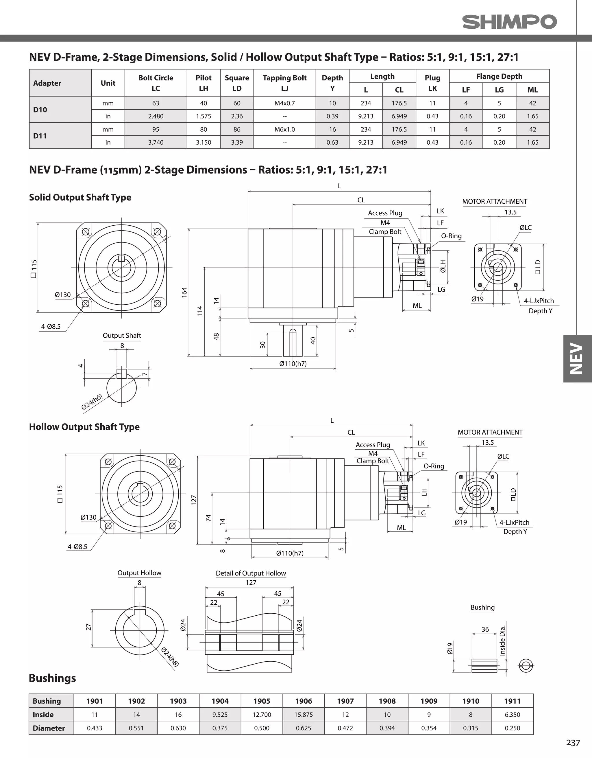
![238
NEV-SERIES Right-angle shaft
NEV D-Frame – 3-Stage Specifications
Frame Size D (115mm)
Stage 3-Stage
Ratio Units Note 45 75 105
Nominal Output Torque [Nm] -- 45 50 50
Maximum Acceleration Torque [Nm] -- 80 80 80
Emergency Stop Torque [Nm] -- 180 180 180
Nominal Input Speed [rpm] -- 3000
Maximum Input Speed [rpm] -- 6000
No Load Running Torque [Nm] -- 0.355
Permitted Radial Load [N] -- 2600 2600 2600
Permitted Axial Load [N] -- 1300 1300 1300
Moment of Inertia (≤Ø14) [kgcm2] -- 0.806 0.694 0.648
Moment of Inertia (≤ Ø19) [kgcm2] -- -- -- --
Efficiency [%] -- 80
Torsional Rigidity [Nm/arcmin] -- 1.5
Maximum Torsional Backlash [Arc-min] -- ≤ 30
Noise Level [dB] -- ≤ 67
Protection Class -- -- IP65
Ambient Temperature [°C] -- 0-40
Permitted Housing Temperature [°C] -- 90
Weight (Solid Output Shaft) [kg] -- 7.3
Weight (Hollow Output Shaft) [kg] -- 6.9
NEV D-Frame, 3-Stage Dimensions, Solid / Hollow Output Shaft Type – Ratios: 45:1, 75:1, 105:1
Adapter Unit
Bolt Circle
LC
Pilot
LH
Square
LD
Tapping Bolt
LJ
Depth
Y
Length Plug
LK
Flange Depth
L CL LF LG ML
D1
mm 60 50 60 M4x0.7 10 236.5 179 11 4 5 42
in 2.362 1.969 2.36 -- 0.39 9.311 7.047 0.43 0.16 0.20 1.65
D1
mm 70 50 60 M4x0.7 10 236.5 179 11 4 5 42
in 2.756 1.969 2.36 -- 0.39 9.311 7.047 0.43 0.16 0.20 1.65
D7
mm 70 50 60 M5x0.8 12 240.5 183 15 6 9 46
in 2.756 1.969 2.36 -- 0.47 9.469 7.205 0.59 0.24 0.35 1.81
D2
mm 90 70 80 M5X0.8 12 236.5 179 11 4 5 42
in 3.543 2.756 3.15 -- 0.47 9.311 7.047 0.43 0.16 0.20 1.65
D8
mm 90 70 80 M6X1.0 21 241.5 184 16 9 10 47
in 3.543 2.756 3.15 -- 0.83 9.508 7.244 0.63 0.35 0.39 1.85
D3
mm 100 80 86 M6X1.0 16 236.5 179 11 4 5 42
in 3.937 3.150 3.39 -- 0.63 9.311 7.047 0.43 0.16 0.20 1.65
D4 mm 98.43 73.025 83 M5X0.8 12 236.5 179 11 4 5 42
(NEMA34) in 3.875 2.875 3.27 -- 0.47 9.311 7.047 0.43 0.16 0.20 1.65
D4+Spacer mm 98.43 73.025 83 M5X0.8 12 244.5 187 19 3 13 50
(NEMA34) in 3.875 2.875 3.27 -- 0.47 9.626 7.362 0.75 0.12 0.51 1.97
D5
mm 75 60 67 M5X0.8 12 236.5 179 11 4 5 42
in 2.953 2.362 2.64 -- 0.47 9.311 7.047 0.43 0.16 0.20 1.65
D6
mm 115 95 100 M6X1.0 16 236.5 179 11 4 5 42
in 4.528 3.740 3.94 -- 0.63 9.311 7.047 0.43 0.16 0.20 1.65
D9 mm 66.68 38.100 60 M4X0.7 10 236.5 179 11 4 5 42
(NEMA23) in 2.625 1.500 2.36 -- 0.39 9.311 7.047 0.43 0.16 0.20 1.65
D14
mm 66.68 38.100 60 M5X0.8 12 244.5 187 18 11 13 50
in 2.625 1.500 2.36 -- 0.47 9.626 7.362 0.71 0.43 0.51 1.97](https://image.slidesharecdn.com/shimpohighprecisioncatalog-140807090507-phpapp01/75/Shimpo-high-precision-catalog-240-2048.jpg)

![240
NEV-SERIES Right-angle shaft
NEV E-Frame – 2-Stage Specifications
Frame Size E (145mm)
Stage 2-Stage
Ratio Units Note 5 9 15 27
Nominal Output Torque [Nm] -- 50 50 55 60
Maximum Acceleration Torque [Nm] -- 100 140 140 180
Emergency Stop Torque [Nm] -- 250 250 250 300
Nominal Input Speed [rpm] -- 3000
Maximum Input Speed [rpm] -- 6000
No Load Running Torque [Nm] -- 1.21
Permitted Radial Load [N] -- 3000 3000 3000 4000
Permitted Axial Load [N] -- 1500 1500 1500 2000
Moment of Inertia (≤Ø19) [kgcm2] -- -- -- -- --
Moment of Inertia (≤ Ø24) [kgcm2] -- 3.559 2.940 1.193 2.044
Efficiency [%] -- 85
Torsional Rigidity [Nm/arcmin] -- 3.2 4.0 4.0 4.0
Maximum Torsional Backlash [Arc-min] -- ≤ 30
Noise Level [dB] -- ≤ 74
Protection Class -- -- IP65
Ambient Temperature [°C] -- 0-40
Permitted Housing Temperature [°C] -- 90
Weight (Solid Output Shaft) [kg] -- 11.0
Weight (Hollow Output Shaft) [kg] -- 10.0
NEV E-Frame, 2-Stage Dimensions, Solid / Hollow Output Shaft Type – Ratios: 5:1, 9:1, 15:1, 27:1
Adapter Unit
Bolt Circle
LC
Pilot
LH
Square
LD
Tapping Bolt
LJ
Depth
Y
Length Plug
LK
Flange Depth
L CL LF LG ML
E1
mm 115 95 100 M6x1.0 15 282.5 210 15 4 7 57
in 4.528 3.740 3.94 -- 0.59 11.122 8.268 0.59 0.16 0.28 2.24
E2
mm 90 70 80 M5x0.8 12 282.5 210 14 4 7 57
in 3.543 2.756 3.15 -- 0.47 11.122 8.268 0.55 0.16 0.28 2.24
E7
mm 90 70 80 M6x1.0 15 285.5 213 17 6 10 60
in 3.543 2.756 3.15 -- 0.59 11.240 8.386 0.67 0.24 0.39 2.36
E3
mm 100 80 90 M6x1.0 15 282.5 210 14 4 7 57
in 3.937 3.150 3.54 -- 0.59 11.122 8.268 0.55 0.16 0.28 2.24
E4 mm 125.73 55.563 108 M6x1.0 15 282.5 210 15 5 7 57
(NEMA42) in 4.950 2.188 4.25 -- 0.59 11.122 8.268 0.59 0.20 0.28 2.24
E5
mm 145 110 130 M8X1.25 16 285.5 213 18 6 10 60
in 5.709 4.331 5.12 -- 0.63 11.240 8.386 0.71 0.24 0.39 2.36
E6
mm 130 110 115 M8X1.25 16 282.5 210 15 6 7 60
in 5.118 4.331 4.53 -- 0.63 11.122 8.268 0.59 0.24 0.28 2.36
E11 mm 98.43 73.025 90 M5x0.8 12 282.5 210 14 4 7 57
(NEMA34) in 3.875 2.875 3.54 -- 0.47 11.122 8.268 0.55 0.16 0.28 2.24
E12 mm 149.22 114.300 130 -- - 285.5 213 18 6 10 60
(NEMA56) in 5.875 4.500 5.12 3/8UNC-16 - 11.240 8.386 0.71 0.24 0.39 2.36
E13
mm 66.7 38.1 80 M4x0.7 10 282.5 210 14 4 7 57
in 2.626 1.500 3.15 -- 0.39 11.122 8.268 0.55 0.16 0.28 2.24
E14
mm 70 50 80 M4x0.7 10 282.5 210 14 4 7 57
in 2.756 1.969 3.15 -- 0.39 11.122 8.268 0.55 0.16 0.28 2.24
E15
mm 75 60 80 M5x0.8 12 282.5 210 14 4 7 57
in 2.953 2.362 3.15 -- 0.47 11.122 8.268 0.55 0.16 0.28 2.24](https://image.slidesharecdn.com/shimpohighprecisioncatalog-140807090507-phpapp01/75/Shimpo-high-precision-catalog-242-2048.jpg)
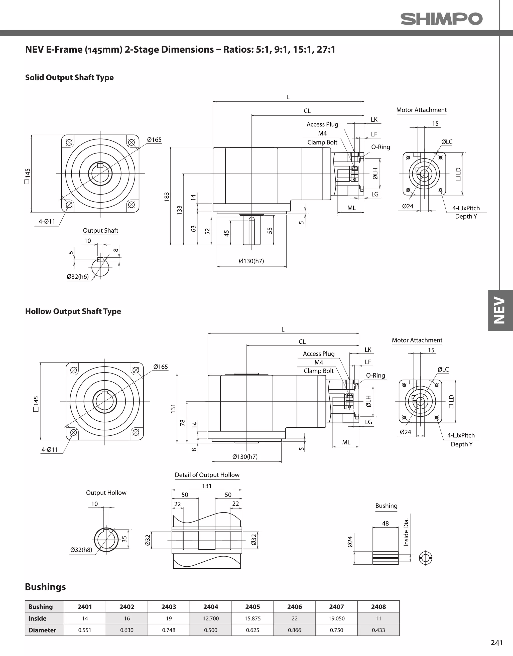
![242
NEV-SERIES Right-angle shaft
NEV E-Frame – 3-Stage Specifications
Frame Size E (145mm)
Stage 3-Stage
Ratio Units Note 45 75 105
Nominal Output Torque [Nm] -- 80 90 90
Maximum Acceleration Torque [Nm] -- 180 180 180
Emergency Stop Torque [Nm] -- 300 300 300
Nominal Input Speed [rpm] -- 3000
Maximum Input Speed [rpm] -- 6000
No Load Running Torque [Nm] -- 0.961
Permitted Radial Load [N] -- 4000 4000 4000
Permitted Axial Load [N] -- 2000 2000 2000
Moment of Inertia (≤Ø19) [kgcm2] -- 1.878 1.303 1.184
Moment of Inertia (≤ Ø24) [kgcm2] -- -- -- --
Efficiency [%] -- 80
Torsional Rigidity [Nm/arcmin] -- 4.0
Maximum Torsional Backlash [Arc-min] -- ≤ 30
Noise Level [dB] -- ≤ 69
Protection Class -- -- IP65
Ambient Temperature [°C] -- 0-40
Permitted Housing Temperature [°C] -- 90
Weight (Solid Output Shaft) [kg] -- 11.4
Weight (Hollow Output Shaft) [kg] -- 10.4
Adapter Unit
Bolt Circle
LC
Pilot
LH
Square
LD
Tapping Bolt
LJ
Depth
Y
Length Plug
LK
Flange Depth
L CL LF LG ML
E1
mm 115 95 100 M6x1.0 15 283.5 211 15 4 7 57
in 4.528 3.740 3.94 - 0.59 11.161 8.307 0.59 0.16 0.28 2.24
E2
mm 90 70 80 M5x0.8 12 283.5 211 14 4 7 57
in 3.543 2.756 3.15 - 0.47 11.161 8.307 0.55 0.16 0.28 2.24
E7
mm 90 70 80 M6x1.0 15 286.5 214 17 6 10 60
in 3.543 2.756 3.15 - 0.59 11.280 8.425 0.67 0.24 0.39 2.36
E3
mm 100 80 90 M6x1.0 15 283.5 211 14 4 7 57
in 3.937 3.150 3.54 - 0.59 11.161 8.307 0.55 0.16 0.28 2.24
E4 mm 125.73 55.563 108 M6x1.0 15 283.5 211 15 5 7 57
(NEMA42) in 4.950 2.188 4.25 - 0.59 11.161 8.307 0.59 0.20 0.28 2.24
E5
mm 145 110 130 M8X1.25 16 286.5 214 18 6 10 60
in 5.709 4.331 5.12 - 0.63 11.280 8.425 0.71 0.24 0.39 2.36
E6
mm 130 110 115 M8X1.25 16 283.5 211 15 6 7 60
in 5.118 4.331 4.53 - 0.63 11.161 8.307 0.59 0.24 0.28 2.36
E11 mm 98.43 73.025 90 M5x0.8 12 283.5 211 14 4 7 57
(NEMA34) in 3.875 2.875 3.54 - 0.47 11.161 8.307 0.55 0.16 0.28 2.24
E12 mm 149.22 114.300 130 - - 286.5 214 18 6 10 60
(NEMA56) in 5.875 4.500 5.12 3/8UNC-16 - 11.280 8.425 0.71 0.24 0.39 2.36
E13
mm 66.7 38.1 80 M4x0.7 10 283.5 211 14 4 7 57
in 2.626 1.500 3.15 - 0.39 11.161 8.307 0.55 0.16 0.28 2.24
E14
mm 70 50 80 M4x0.7 10 283.5 211 14 4 7 57
in 2.756 1.969 3.15 - 0.39 11.161 8.307 0.55 0.16 0.28 2.24
E15
mm 75 60 80 M5x0.8 12 283.5 211 14 4 7 57
in 2.953 2.362 3.15 - 0.47 11.161 8.307 0.55 0.16 0.28 2.24
NEV E-Frame, 3-Stage Dimensions, Solid / Hollow Output Shaft Type – Ratios: 45:1, 75:1, 105:1](https://image.slidesharecdn.com/shimpohighprecisioncatalog-140807090507-phpapp01/75/Shimpo-high-precision-catalog-244-2048.jpg)
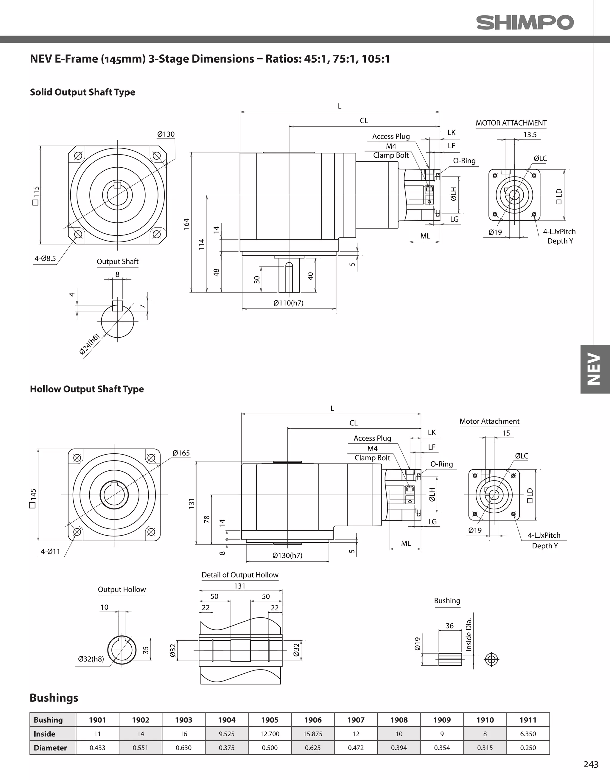


![248
EVL-SERIES Right-angle shaft
EVL-070 – 2-Stage Specifications
EVL-070 – 3-Stage Specifications
Frame Size 070
Stage 2-Stage
Ratio Unit Note 3 4 5 6 7 8 9 10
Nominal Output Torque [Nm] *1 12 16 22 24 24 24 16 16
Maximum Acceleration Torque [Nm] *2 24 32 40 45 45 45 32 32
Emergency Stop Torque [Nm] *3 50 65 80 90 90 90 65 65
Nominal Input Speed [rpm] *4 3000
Maximum Input Speed [rpm] *5 6000
No Load Running Torque [Nm] *6 0.33
Permitted Radial Load [N] *7 430 470 510 540 570 600 620 640
Permitted Axial Load [N] *8 310 360 390 430 460 480 510 530
Maximum Radial Load [N] *9 1200
Maximum Axial Load [N] *10 1100
Moment of Inertia (≤ Ø 8) [kgcm2] -- 0.310 0.270 0.250 0.240 0.230 0.230 0.230 0.230
Moment of Inertia (≤ Ø 14) [kgcm2] -- 0.390 0.340 0.320 0.310 0.310 0.310 0.300 0.300
Moment of Inertia (≤ Ø 19) [kgcm2] -- 0.580 0.530 0.510 0.500 0.500 0.500 0.490 0.490
Efficiency [%] *11 93
Torsional Rigidity [Nm/arc-min] *12 3
Maximum Torsional Backlash [arc-min] -- ≤ 6
Noise Level [dB] *13 80
Protection Class -- *14 IP54 (IP65)
Ambient Temperature [°C] -- 0-40
Permitted Housing Temperature [°C] -- 90
Weight [kg] *15 1.9
Frame Size 070
Stage 3-Stage
Ratio Unit Note 15 16 20 25 28 30 35 40
Nominal Output Torque [Nm] *1 16 24 24 24 24 16 24 24
Maximum Acceleration Torque [Nm] *2 32 45 45 45 45 32 45 45
Emergency Stop Torque [Nm] *3 65 90 90 90 90 65 90 90
Nominal Input Speed [rpm] *4 3000
Maximum Input Speed [rpm] *5 6000
No Load Running Torque [Nm] *6 0.20
Permitted Radial Load [N] *7 740 750 810 870 910 930 980 100
Permitted Axial Load [N] *8 630 650 720 790 830 860 920 970
Maximum Radial Load [N] *9 1200
Maximum Axial Load [N] *10 1100
Moment of Inertia (≤ Ø 8) [kgcm2] -- 0.073 0.079 0.071 0.071 0.077 0.062 0.070 0.061
Moment of Inertia (≤ Ø 14) [kgcm2] -- 0.118 0.124 0.116 0.115 0.122 0.106 0.115 0.106
Moment of Inertia (≤ Ø 19) [kgcm2] -- -- -- -- -- -- -- -- --
Efficiency [%] *11 88
Torsional Rigidity [Nm/arc-min] *12 3
Maximum Torsional Backlash [arc-min] -- ≤ 9
Noise Level [dB] *13 80
Protection Class -- *14 IP54 (IP65)
Ambient Temperature [°C] -- 0-40
Permitted Housing Temperature [°C] -- 90
Weight [kg] *15 1.7](https://image.slidesharecdn.com/shimpohighprecisioncatalog-140807090507-phpapp01/75/Shimpo-high-precision-catalog-250-2048.jpg)
![249
EVL
EVL-070 – 3-Stage Specifications
Frame Size 070
Stage 3-Stage
Ratio Unit Note 45 50 60 70 80 90 100
Nominal Output Torque [Nm] *1 16 24 24 24 24 16 16
Maximum Acceleration Torque [Nm] *2 32 45 45 45 45 32 32
Emergency Stop Torque [Nm] *3 65 90 90 90 90 65 65
Nominal Input Speed [rpm] *4 3000
Maximum Input Speed [rpm] *5 6000
No Load Running Torque [Nm] *6 0.20
Permitted Radial Load [N] *7 1100 1100 1200 1200 1200 1200 1200
Permitted Axial Load [N] *8 1000 1100 1100 1100 1100 1100 1100
Maximum Radial Load [N] *9 1200
Maximum Axial Load [N] *10 1100
Moment of Inertia (≤ Ø 8) [kgcm2] -- 0.070 0.061 0.061 0.061 0.061 0.061 0.061
Moment of Inertia (≤ Ø 14) [kgcm2] -- 0.115. 0.106 0.106 0.105 0.105 0.105 0.105
Moment of Inertia (≤ Ø 19) [kgcm2] -- -- -- -- -- -- -- --
Efficiency [%] *11 88
Torsional Rigidity [Nm/arc-min] *12 3
Maximum Torsional Backlash [arc-min] -- ≤ 9
Noise Level [dB] *13 80
Protection Class -- *14 IP54 (IP65)
Ambient Temperature [°C] -- 0-40
Permitted Housing Temperature [°C] -- 90
Weight [kg] *15 1.7
*1) At nominal input speed, service life is 20,000 hours
*2) The maximum torque when starting or stopping operation
*3) The maximum torque allowed under a stress situation (Permitted 1,000 times during service life)
*4) The average input speed
*5) The maximum intermittent input speed
*6) This is the torque at no load applied on the input shaft. The input speed is 3000 rpm for EVL070
*7) At this load and nominal input speed, service life will be 20,000 hours. (The radial load applied to the output side bearing)
*8) At this load and nominal input speed, service life will be 20,000 hours. (The axial load applied to the output shaft center)
*9) The maximum radial load that the reducer can accept
*10) The maximum axial load that the reducer can accept
*11) The efficiency at the nominal torque rating
*12) This does not include the lost motion
*13) Contact NIDEC-SHIMPO for the testing conditions and environment
*14) IP65 (wash-down) is available as an option. Contact NIDEC-SHIMPO for more details and our food grade options
*15) The weight may vary slightly between models](https://image.slidesharecdn.com/shimpohighprecisioncatalog-140807090507-phpapp01/75/Shimpo-high-precision-catalog-251-2048.jpg)
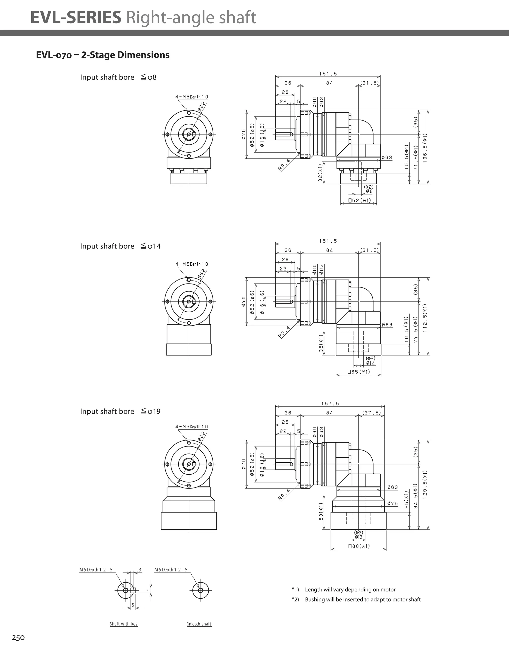


![254
EVL-SERIES Right-angle shaft
EVL-090 – 2-Stage Specifications
EVL-090 – 3-Stage Specifications
Frame Size 090
Stage 2-Stage
Ratio Unit Note 3 4 5 6 7 8 9 10
Nominal Output Torque [Nm] *1 45 60 65 65 65 65 45 45
Maximum Acceleration Torque [Nm] *2 65 90 90 90 90 90 65 65
Emergency Stop Torque [Nm] *3 130 170 220 220 220 220 170 170
Nominal Input Speed [rpm] *4 3000
Maximum Input Speed [rpm] *5 6000
No Load Running Torque [Nm] *6 1.13
Permitted Radial Load [N] *7 810 890 960 1000 1100 1100 1200 1200
Permitted Axial Load [N] *8 930 1100 1200 1300 1300 1400 1500 1600
Maximum Radial Load [N] *9 2400
Maximum Axial Load [N] *10 2200
Moment of Inertia (≤ Ø 8) [kgcm2] -- -- -- -- -- -- -- -- --
Moment of Inertia (≤ Ø 14) [kgcm2] -- 2.120 1.890 1.800 1.760 1.730 1.710 1.700 1.690
Moment of Inertia (≤ Ø 19) [kgcm2] -- 2.450 2.220 2.130 2.090 2.060 2.040 2.030 2.020
Moment of Inertia (≤ Ø 28) [kgcm2] -- 4.570 4.350 4.260 4.210 4.180 4.170 4.160 4.150
Efficiency [%] *11 93
Torsional Rigidity [Nm/arc-min] *12 10
Maximum Torsional Backlash [arc-min] -- ≤ 6
Noise Level [dB] *13 80
Protection Class -- *14 IP54 (IP65)
Ambient Temperature [°C] -- 0-40
Permitted Housing Temperature [°C] -- 90
Weight [kg] *15 4.9
Frame Size 090
Stage 3-Stage
Ratio Unit Note 15 16 20 25 28 30 35 40
Nominal Output Torque [Nm] *1 45 65 65 65 65 45 65 65
Maximum Acceleration Torque [Nm] *2 65 110 110 110 110 65 110 110
Emergency Stop Torque [Nm] *3 170 220 220 220 220 170 220 220
Nominal Input Speed [rpm] *4 3000
Maximum Input Speed [rpm] *5 6000
No Load Running Torque [Nm] *6 0.55
Permitted Radial Load [N] *7 1400 1400 1500 1600 1700 1700 1800 1900
Permitted Axial Load [N] *8 1900 1900 2100 2200 2200 2200 2200 2200
Maximum Radial Load [N] *9 2400
Maximum Axial Load [N] *10 2200
Moment of Inertia (≤ Ø 8) [kgcm2] -- 0.340 0.380 0.330 0.320 0.370 0.250 0.320 0.250
Moment of Inertia (≤ Ø 14) [kgcm2] -- 0.410 0.460 0.400 0.400 0.450 0.330 0.400 0.320
Moment of Inertia (≤ Ø 19) [kgcm2] -- 0.600 0.650 0.590 0.590 0.640 0.510 0.590 0.510
Moment of Inertia (≤ Ø 28) [kgcm2] -- -- -- -- -- -- -- -- --
Efficiency [%] *11 88
Torsional Rigidity [Nm/arc-min] *12 10
Maximum Torsional Backlash [arc-min] -- ≤ 9
Noise Level [dB] *13 80
Protection Class -- *14 IP54 (IP65)
Ambient Temperature [°C] -- 0-40
Permitted Housing Temperature [°C] -- 90
Weight [kg] *15 4.3](https://image.slidesharecdn.com/shimpohighprecisioncatalog-140807090507-phpapp01/75/Shimpo-high-precision-catalog-256-2048.jpg)
![255
EVL
EVL-090 – 3-Stage Specifications
Frame Size 090
Stage 3-Stage
Ratio Unit Note 45 50 60 70 80 90 100
Nominal Output Torque [Nm] *1 45 65 65 65 65 45 45
Maximum Acceleration Torque [Nm] *2 65 110 1110 110 110 65 65
Emergency Stop Torque [Nm] *3 170 220 220 220 220 170 170
Nominal Input Speed [rpm] *4 3000
Maximum Input Speed [rpm] *5 6000
No Load Running Torque [Nm] *6 0.55
Permitted Radial Load [N] *7 2000 2100 2200 2300 2400 2400 2400
Permitted Axial Load [N] *8 2200 2200 2200 2200 2200 2200 2200
Maximum Radial Load [N] *9 2400
Maximum Axial Load [N] *10 2200
Moment of Inertia (≤ Ø 8) [kgcm2] -- 0.320 0.250 0.250 0.250 0.250 0.250 0.250
Moment of Inertia (≤ Ø 14) [kgcm2] -- 0.390 0.320 0.320 0.320 0.320 0.320 0.320
Moment of Inertia (≤ Ø 19) [kgcm2] -- 0.580 0.510 0.510 0.510 0.510 0.510 0.510
Moment of Inertia (≤ Ø 28) [kgcm2] -- -- -- -- -- -- -- --
Efficiency [%] *11 88
Torsional Rigidity [Nm/arc-min] *12 10
Maximum Torsional Backlash [arc-min] -- ≤ 9
Noise Level [dB] *13 80
Protection Class -- *14 IP54 (IP65)
Ambient Temperature [°C] -- 0-40
Permitted Housing Temperature [°C] -- 90
Weight [kg] *15 4.3
*1) At nominal input speed, service life is 20,000 hours
*2) The maximum torque when starting or stopping operation
*3) The maximum torque allowed under a stress situation (Permitted 1,000 times during service life)
*4) The average input speed
*5) The maximum intermittent input speed
*6) This is the torque at no load applied on the input shaft. The input speed is 3000 rpm for EVL090
*7) At this load and nominal input speed, service life will be 20,000 hours. (The radial load applied to the output side bearing)
*8) At this load and nominal input speed, service life will be 20,000 hours. (The axial load applied to the output shaft center)
*9) The maximum radial load that the reducer can accept
*10) The maximum axial load that the reducer can accept
*11) The efficiency at the nominal torque rating
*12) This does not include the lost motion
*13) Contact NIDEC-SHIMPO for the testing conditions and environment
*14) IP65 (wash-down) is available as an option. Contact NIDEC-SHIMPO for more details and our food grade options
*15) The weight may vary slightly between models](https://image.slidesharecdn.com/shimpohighprecisioncatalog-140807090507-phpapp01/75/Shimpo-high-precision-catalog-257-2048.jpg)


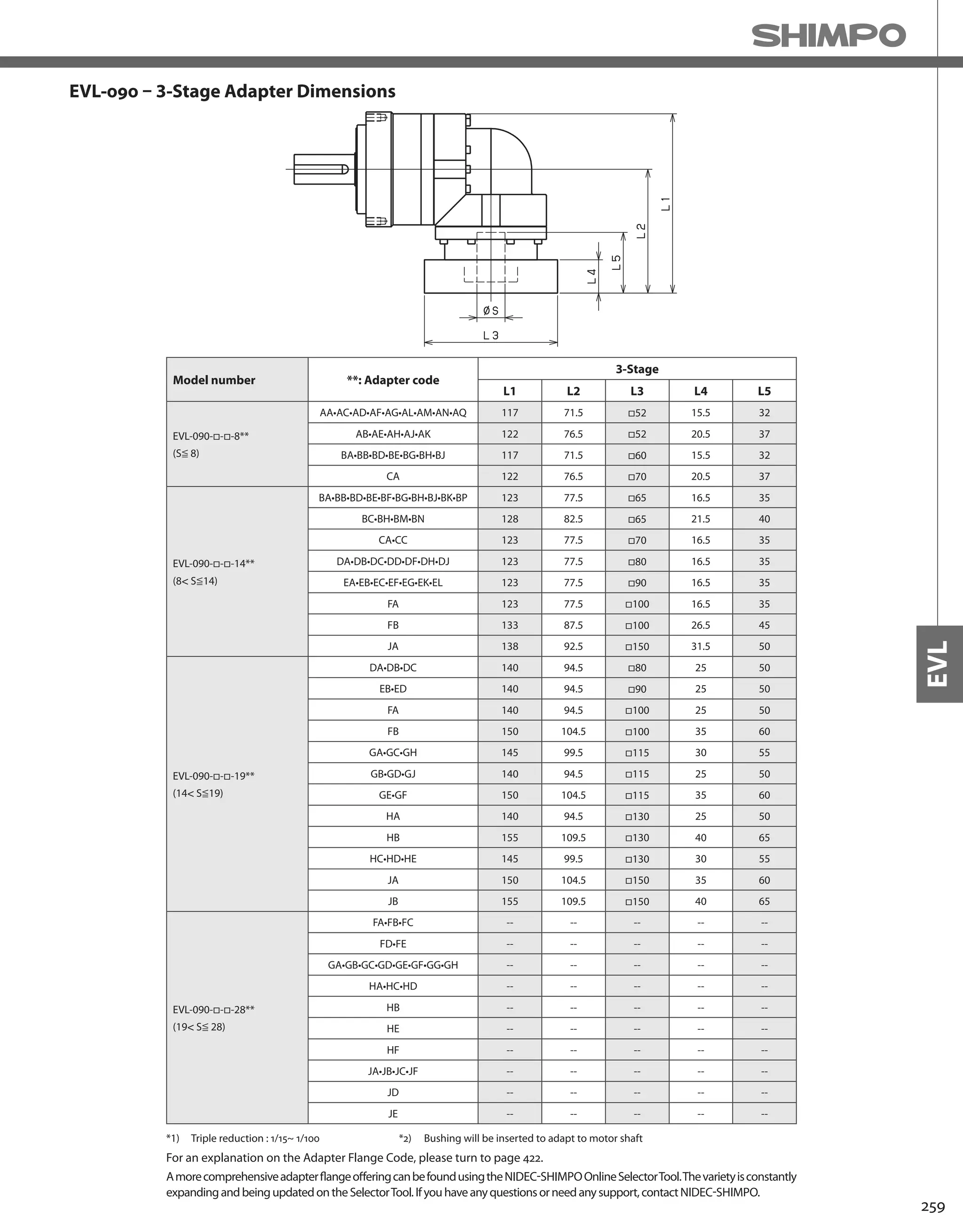
![260
EVL-SERIES Right-angle shaft
EVL-120 – 2-Stage Specifications
EVL-120 – 3-Stage Specifications
Frame Size 120
Stage 2-Stage
Ratio Unit Note 3 4 5 6 7 8 9 10
Nominal Output Torque [Nm] *1 75 100 120 150 150 150 110 110
Maximum Acceleration Torque [Nm] *2 150 200 240 300 300 300 200 200
Emergency Stop Torque [Nm] *3 320 430 500 550 550 550 450 450
Nominal Input Speed [rpm] *4 3000
Maximum Input Speed [rpm] *5 6000
No Load Running Torque [Nm] *6 1.88
Permitted Radial Load [N] *7 1300 1500 1600 1700 1800 1900 1900 2000
Permitted Axial Load [N] *8 1500 1700 1900 2000 2100 2300 2400 2500
Maximum Radial Load [N] *9 4300
Maximum Axial Load [N] *10 3900
Moment of Inertia (≤ Ø 14) [kgcm2] -- -- -- -- -- -- -- -- --
Moment of Inertia (≤ Ø 19) [kgcm2] -- 6.740 5.490 5.020 4.770 4.650 4.550 4.490 4.460
Moment of Inertia (≤ Ø 28) [kgcm2] -- 8.340 7.080 6.610 6.360 6.240 6.140 6.080 6.050
Moment of Inertia (≤ Ø 38) [kgcm2] -- 15.410 14.150 13.690 13.430 13.310 13.220 13.160 13.120
Efficiency [%] *11 93
Torsional Rigidity [Nm/arc-min] *12 31
Maximum Torsional Backlash [arc-min] -- ≤ 6
Noise Level [dB] *13 85
Protection Class -- *14 IP54 (IP65)
Ambient Temperature [°C] -- 0-40
Permitted Housing Temperature [°C] -- 90
Weight [kg] *15 10.2
Frame Size 120
Stage 3-Stage
Ratio Unit Note 15 16 20 25 28 30 35 40
Nominal Output Torque [Nm] *1 110 130 150 150 150 110 150 150
Maximum Acceleration Torque [Nm] *2 200 260 300 300 300 200 300 300
Emergency Stop Torque [Nm] *3 450 550 550 550 550 450 550 550
Nominal Input Speed [rpm] *4 3000
Maximum Input Speed [rpm] *5 6000
No Load Running Torque [Nm] *6 1.11
Permitted Radial Load [N] *7 2300 2300 2500 2700 2800 2900 3000 3200
Permitted Axial Load [N] *8 3000 3100 3400 3700 3900 3900 3900 3900
Maximum Radial Load [N] *9 4300
Maximum Axial Load [N] *10 3900
Moment of Inertia (≤ Ø 14) [kgcm2] -- 2.250 2.460 2.200 2.180 2.400 1.870 2.160 1.860
Moment of Inertia (≤ Ø 19) [kgcm2] -- 2.580 2.790 2.530 2.510 2.730 2.200 2.490 2.190
Moment of Inertia (≤ Ø 28) [kgcm2] -- 4.700 4.910 4.650 4.640 4.860 4.330 4.620 4.320
Moment of Inertia (≤ Ø 38) [kgcm2] -- -- -- -- -- -- -- -- --
Efficiency [%] *11 88
Torsional Rigidity [Nm/arc-min] *12 31
Maximum Torsional Backlash [arc-min] -- ≤ 9
Noise Level [dB] *13 85
Protection Class -- *14 IP54 (IP65)
Ambient Temperature [°C] -- 0-40
Permitted Housing Temperature [°C] -- 90
Weight [kg] *15 10](https://image.slidesharecdn.com/shimpohighprecisioncatalog-140807090507-phpapp01/75/Shimpo-high-precision-catalog-262-2048.jpg)
![261
EVL
EVL-120 – 3-Stage Specifications
Frame Size 120
Stage 3-Stage
Ratio Unit Note 45 50 60 70 80 90 100
Nominal Output Torque [Nm] *1 110 150 150 150 150 110 110
Maximum Acceleration Torque [Nm] *2 200 300 300 300 300 200 200
Emergency Stop Torque [Nm] *3 450 550 550 550 550 450 450
Nominal Input Speed [rpm] *4 3000
Maximum Input Speed [rpm] *5 6000
No Load Running Torque [Nm] *6 1.11
Permitted Radial Load [N] *7 3300 3400 3600 3800 4000 4200 4300
Permitted Axial Load [N] *8 3900 3900 3900 3900 3900 3900 3900
Maximum Radial Load [N] *9 4300
Maximum Axial Load [N] *10 3900
Moment of Inertia (≤ Ø 14) [kgcm2] -- 2.150 1.860 1.850 1.850 1.850 1.850 1.850
Moment of Inertia (≤ Ø 19) [kgcm2] -- 2.480 2.190 2.180 2.180 2.180 2.180 2.180
Moment of Inertia (≤ Ø 28) [kgcm2] -- 4.610 4.310 4.310 4.310 4.310 4.310 4.310
Moment of Inertia (≤ Ø 38) [kgcm2] -- -- -- -- -- -- -- --
Efficiency [%] *11 88
Torsional Rigidity [Nm/arc-min] *12 31
Maximum Torsional Backlash [arc-min] -- ≤ 9
Noise Level [dB] *13 85
Protection Class -- *14 IP54 (IP65)
Ambient Temperature [°C] -- 0-40
Permitted Housing Temperature [°C] -- 90
Weight [kg] *15 10
*1) At nominal input speed, service life is 20,000 hours
*2) The maximum torque when starting or stopping operation
*3) The maximum torque allowed under a stress situation (Permitted 1,000 times during service life)
*4) The average input speed
*5) The maximum intermittent input speed
*6) This is the torque at no load applied on the input shaft. The input speed is 3000 rpm for EVL120
*7) At this load and nominal input speed, service life will be 20,000 hours. (The radial load applied to the output side bearing)
*8) At this load and nominal input speed, service life will be 20,000 hours. (The axial load applied to the output shaft center)
*9) The maximum radial load that the reducer can accept
*10) The maximum axial load that the reducer can accept
*11) The efficiency at the nominal torque rating
*12) This does not include the lost motion
*13) Contact NIDEC-SHIMPO for the testing conditions and environment
*14) IP65 (wash-down) is available as an option. Contact NIDEC-SHIMPO for more details and our food grade options
*15) The weight may vary slightly between models](https://image.slidesharecdn.com/shimpohighprecisioncatalog-140807090507-phpapp01/75/Shimpo-high-precision-catalog-263-2048.jpg)


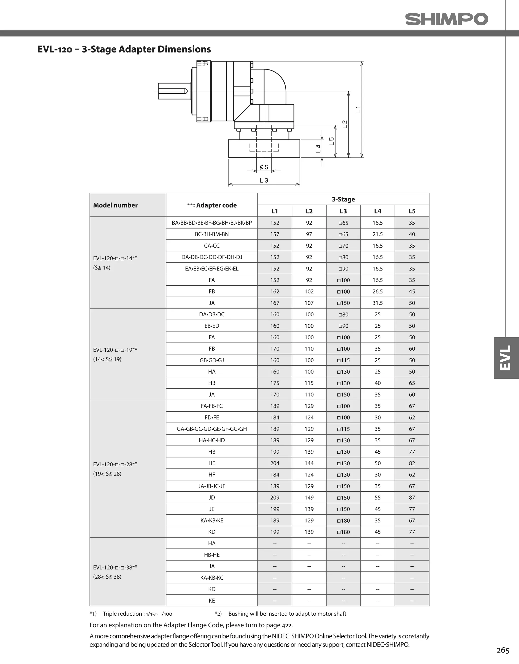
![266
EVL-SERIES Right-angle shaft
EVL-155 – 2-Stage Specifications
EVL-155 – 3-Stage Specifications
Frame Size 155
Stage 2-Stage
Ratio Unit Note 3 4 5 6 7 8 9 10
Nominal Output Torque [Nm] *1 130 170 200 260 300 300 200 200
Maximum Acceleration Torque [Nm] *2 260 340 400 520 600 600 400 400
Emergency Stop Torque [Nm] *3 700 950 1100 1100 1100 1100 750 750
Nominal Input Speed [rpm] *4 2000
Maximum Input Speed [rpm] *5 4000
No Load Running Torque [Nm] *6 3.26
Permitted Radial Load [N] *7 3200 3500 3800 4000 4200 4400 4600 4700
Permitted Axial Load [N] *8 2400 2700 3000 3300 3500 3700 3900 4100
Maximum Radial Load [N] *9 9100
Maximum Axial Load [N] *10 8200
Moment of Inertia (≤ Ø 19) [kgcm2] -- -- -- -- -- -- -- -- --
Moment of Inertia (≤ Ø 28) [kgcm2] -- 23.130 18.570 16.910 16.010 15.580 15.230 14.770 14.660
Moment of Inertia (≤ Ø 38) [kgcm2] -- 27.500 22.940 21.280 20.380 19.950 19.610 19.410 19.030
Moment of Inertia (≤ Ø 48) [kgcm2] -- 40.730 36.170 34.510 33.610 33.180 32.840 32.370 32.260
Efficiency [%] *11 93
Torsional Rigidity [Nm/arc-min] *12 60
Maximum Torsional Backlash [arc-min] -- ≤ 6
Noise Level [dB] *13 85
Protection Class -- *14 IP54 (IP65)
Ambient Temperature [°C] -- 0-40
Permitted Housing Temperature [°C] -- 90
Weight [kg] *15 19.8
Frame Size 155
Stage 3-Stage
Ratio Unit Note 15 16 20 25 28 30 35 40
Nominal Output Torque [Nm] *1 200 300 300 300 300 200 300 300
Maximum Acceleration Torque [Nm] *2 400 600 600 600 600 400 600 600
Emergency Stop Torque [Nm] *3 750 1100 1100 1100 1100 750 1100 1100
Nominal Input Speed [rpm] *4 2000
Maximum Input Speed [rpm] *5 4000
No Load Running Torque [Nm] *6 2.56
Permitted Radial Load [N] *7 5400 5500 6000 6400 6700 6800 7200 7500
Permitted Axial Load [N] *8 4900 5000 5500 6100 6400 6600 7000 7500
Maximum Radial Load [N] *9 9100
Maximum Axial Load [N] *10 8200
Moment of Inertia (≤ Ø 19) [kgcm2] -- 6.400 7.290 6.220 6.150 7.090 4.990 6.090 4.950
Moment of Inertia (≤ Ø 28) [kgcm2] -- 8.000 8.880 7.810 7.750 8.680 6.580 7.690 6.540
Moment of Inertia (≤ Ø 38) [kgcm2] -- 15.070 15.960 14.890 14.820 15.760 13.660 14.760 13.610
Moment of Inertia (≤ Ø 48) [kgcm2] -- -- -- -- -- -- -- -- --
Efficiency [%] *11 88
Torsional Rigidity [Nm/arc-min] *12 60
Maximum Torsional Backlash [arc-min] -- ≤ 9
Noise Level [dB] *13 85
Protection Class -- *14 IP54 (IP65)
Ambient Temperature [°C] -- 0-40
Permitted Housing Temperature [°C] -- 90
Weight [kg] *15 20.4](https://image.slidesharecdn.com/shimpohighprecisioncatalog-140807090507-phpapp01/75/Shimpo-high-precision-catalog-268-2048.jpg)
![267
EVL
EVL-155 – 3-Stage Specifications
Frame Size 155
Stage 3-Stage
Ratio Unit Note 45 50 60 70 80 90 100
Nominal Output Torque [Nm] *1 200 300 300 300 300 200 200
Maximum Acceleration Torque [Nm] *2 400 600 600 600 600 400 400
Emergency Stop Torque [Nm] *3 750 1100 1100 1100 1100 750 750
Nominal Input Speed [rpm] *4 2000
Maximum Input Speed [rpm] *5 4000
No Load Running Torque [Nm] *6 2.56
Permitted Radial Load [N] *7 7800 8100 8600 9100 9100 9100 9100
Permitted Axial Load [N] *8 7900 8200 8200 8200 8200 8200 8200
Maximum Radial Load [N] *9 9100
Maximum Axial Load [N] *10 8200
Moment of Inertia (≤ Ø 19) [kgcm2] -- 6.070 4.930 4.920 4.910 4.910 4.910 4.910
Moment of Inertia (≤ Ø 28) [kgcm2] -- 7.660 6.520 6.510 6.510 6.500 6.500 6.500
Moment of Inertia (≤ Ø 38) [kgcm2] -- 14.740 13.590 13.590 13.580 13.580 13.570 13.570
Moment of Inertia (≤ Ø 48) [kgcm2] -- -- -- -- -- -- -- --
Efficiency [%] *11 88
Torsional Rigidity [Nm/arc-min] *12 60
Maximum Torsional Backlash [arc-min] -- ≤ 9
Noise Level [dB] *13 85
Protection Class -- *14 IP54 (IP65)
Ambient Temperature [°C] -- 0-40
Permitted Housing Temperature [°C] -- 90
Weight [kg] *15 20.4
*1) At nominal input speed, service life is 20,000 hours
*2) The maximum torque when starting or stopping operation
*3) The maximum torque allowed under a stress situation (Permitted 1,000 times during service life)
*4) The average input speed
*5) The maximum intermittent input speed
*6) This is the torque at no load applied on the input shaft. The input speed is 2000 rpm for EVL155
*7) At this load and nominal input speed, service life will be 20,000 hours. (The radial load applied to the output side bearing)
*8) At this load and nominal input speed, service life will be 20,000 hours. (The axial load applied to the output shaft center)
*9) The maximum radial load that the reducer can accept
*10) The maximum axial load that the reducer can accept
*11) The efficiency at the nominal torque rating
*12) This does not include the lost motion
*13) Contact NIDEC-SHIMPO for the testing conditions and environment
*14) IP65 (wash-down) is available as an option. Contact NIDEC-SHIMPO for more details and our food grade options
*15) The weight may vary slightly between models](https://image.slidesharecdn.com/shimpohighprecisioncatalog-140807090507-phpapp01/75/Shimpo-high-precision-catalog-269-2048.jpg)

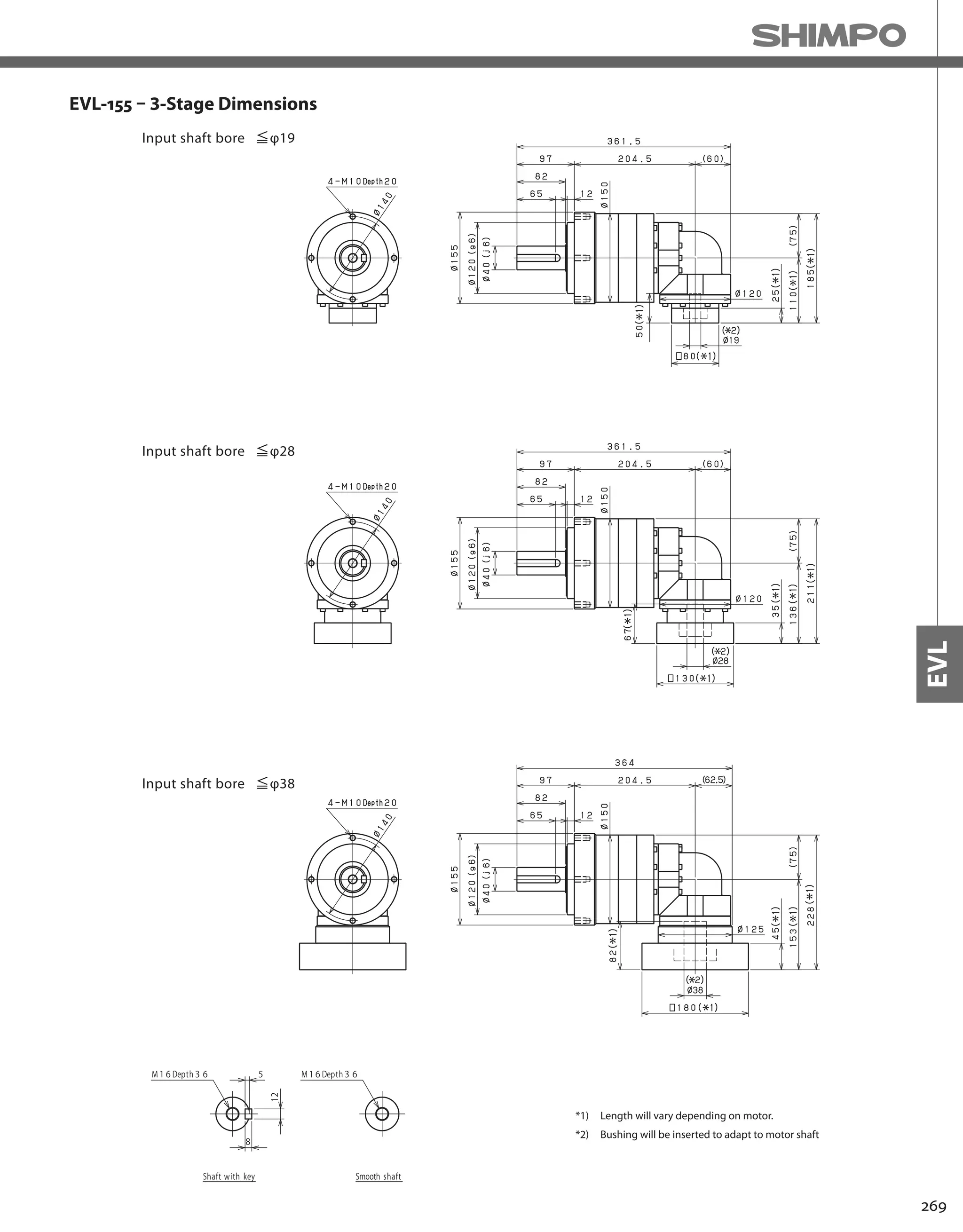


![272
EVL-SERIES Right-angle shaft
EVL-205 – 2-Stage Specifications
Frame Size 205
Stage 2-Stage
Ratio Units Note 3 4 5 6 7 8 9 10
Nominal Output Torque [Nm] *1 400 575 600 600 600 600 400 400
Maximum Acceleration Torque [Nm] *2 575 770 960 1120 1120 1120 775 775
Emergency Stop Torque [Nm] *3 1300 1700 2000 2500 2500 2500 2000 2000
Nominal Input Speed [rpm] *4 1500
Maximum Input Speed [rpm] *5 3000
No Load Running Torque [Nm] *6 10.8
Permitted Radial Load [N] *7 5600 6200 6700 7100 7400 7800 8100 8400
Permitted Axial Load [N] *8 4300 4900 5400 5800 6300 6600 7000 7300
Maximum Radial Load [N] *9 15000
Maximum Axial Load [N] *10 14000
Moment of Inertia (≤Ø 28) [kgcm2] -- -- -- -- -- -- -- -- --
Moment of Inertia (≤Ø 38) [kgcm2] -- 93.71 77.72 71.89 68.74 66.43 65.27 64.60 64.28
Moment of Inertia (≤Ø 48) [kgcm2] -- 128.6 112.6 106.8 103.6 101.3 100.1 99.46 99.14
Moment of Inertia (≤ Ø 65) [kgcm2] -- 214.2 198.2 192.4 189.2 186.9 185.7 185.1 184.7
Efficiency [%] *11 93
Torsional Rigidity [Nm/arcmin] *12 175
Maximum Torsional Backlash [Arc-min] -- ≤ 8
Noise Level [dB] *13 ≤ 85
Protection Class -- *14 IP54 (IP65)
Ambient Temperature [°C] -- 0-40
Permitted Housing Temperature [°C] -- 90
Weight [kg] *15 52
Frame Size 205
Stage 3-Stage
Ratio Units Note 15 16 20 25 28 30 35 40
Nominal Output Torque [Nm] *1 400 555 600 600 600 400 600 600
Maximum Acceleration Torque [Nm] *2 775 1120 1120 1120 1120 775 1120 1120
Emergency Stop Torque [Nm] *3 2000 2500 2500 2500 2500 2000 2500 2500
Nominal Input Speed [rpm] *4 1500
Maximum Input Speed [rpm] *5 3000
No Load Running Torque [Nm] *6 4.7
Permitted Radial Load [N] *7 9600 9800 11000 11000 12000 12000 13000 13000
Permitted Axial Load [N] *8 8700 8900 9900 11000 11000 12000 13000 13000
Maximum Radial Load [N] *9 15000
Maximum Axial Load [N] *10 14000
Moment of Inertia (≤Ø 28) [kgcm2] -- 11.49 12.09 11.15 10.98 11.59 10.33 10.83 10.24
Moment of Inertia (≤Ø 38) [kgcm2] -- 20.28 20.88 19.94 19.77 20.38 19.11 19.62 19.03
Moment of Inertia (≤Ø 48) [kgcm2] -- 25.10 25.70 24.76 24.59 25.20 23.94 24.44 23.85
Moment of Inertia (≤ Ø 65) [kgcm2] -- -- -- -- -- -- -- -- --
Efficiency [%] *11 88
Torsional Rigidity [Nm/arcmin] *12 175
Maximum Torsional Backlash [Arc-min] -- ≤ 11
Noise Level [dB] *13 ≤ 85
Protection Class -- *14 IP54 (IP65)
Ambient Temperature [°C] -- 0-40
Permitted Housing Temperature [°C] -- 90
Weight [kg] *15 39
EVL-205 – 3-Stage Specifications](https://image.slidesharecdn.com/shimpohighprecisioncatalog-140807090507-phpapp01/75/Shimpo-high-precision-catalog-274-2048.jpg)
![273
EVL
EVL-205 – 3-Stage Specifications
Frame Size 205
Stage 3-Stage
Ratio Units Note 45 50 60 70 80 90 100
Nominal Output Torque [Nm] *1 400 600 600 600 600 400 400
Maximum Acceleration Torque [Nm] *2 775 1120 1120 1120 1120 775 775
Emergency Stop Torque [Nm] *3 2000 2500 2500 2500 2500 2000 2000
Nominal Input Speed [rpm] *4 1500
Maximum Input Speed [rpm] *5 3000
No Load Running Torque [Nm] *6 4.7
Permitted Radial Load [N] *7 14000 14000 15000 15000 15000 15000 15000
Permitted Axial Load [N] *8 14000 14000 14000 14000 14000 14000 14000
Maximum Radial Load [N] *9 15000
Maximum Axial Load [N] *10 14000
Moment of Inertia (≤Ø 28) [kgcm2] -- 10.76 10.20 10.18 10.16 10.15 10.15 10.14
Moment of Inertia (≤Ø 38) [kgcm2] -- 19.55 18.99 18.96 18.95 18.94 18.93 18.93
Moment of Inertia (≤Ø 48) [kgcm2] -- 24.37 23.81 23.78 23.77 23.76 23.75 23.75
Moment of Inertia (≤ Ø 65) [kgcm2] -- -- -- -- -- -- -- --
Efficiency [%] *11 88
Torsional Rigidity [Nm/arcmin] *12 175
Maximum Torsional Backlash [Arc-min] -- ≤ 11
Noise Level [dB] *13 ≤ 85
Protection Class -- *14 IP54 (IP65)
Ambient Temperature [°C] -- 0-40
Permitted Housing Temperature [°C] -- 90
Weight [kg] *15 39
*1) At nominal input speed, service life is 20,000 hours
*2) The maximum torque when starting or stopping operation
*3) The maximum torque allowed under a stress situation (Permitted 1,000 times during service life)
*4) The average input speed
*5) The maximum intermittent input speed
*6) This is the torque at no load applied on the input shaft. The input speed is 1500 rpm for EVL205
*7) At this load and nominal input speed, service life will be 20,000 hours. (The radial load applied to the output side bearing)
*8) At this load and nominal input speed, service life will be 20,000 hours. (The axial load applied to the output shaft center)
*9) The maximum radial load that the reducer can accept
*10) The maximum axial load that the reducer can accept
*11) The efficiency at the nominal torque rating
*12) This does not include the lost motion
*13) Contact NIDEC-SHIMPO for the testing conditions and environment
*14) IP65 (wash-down) is available as an option. Contact NIDEC-SHIMPO for more details and our food grade options
*15) The weight may vary slightly between models](https://image.slidesharecdn.com/shimpohighprecisioncatalog-140807090507-phpapp01/75/Shimpo-high-precision-catalog-275-2048.jpg)

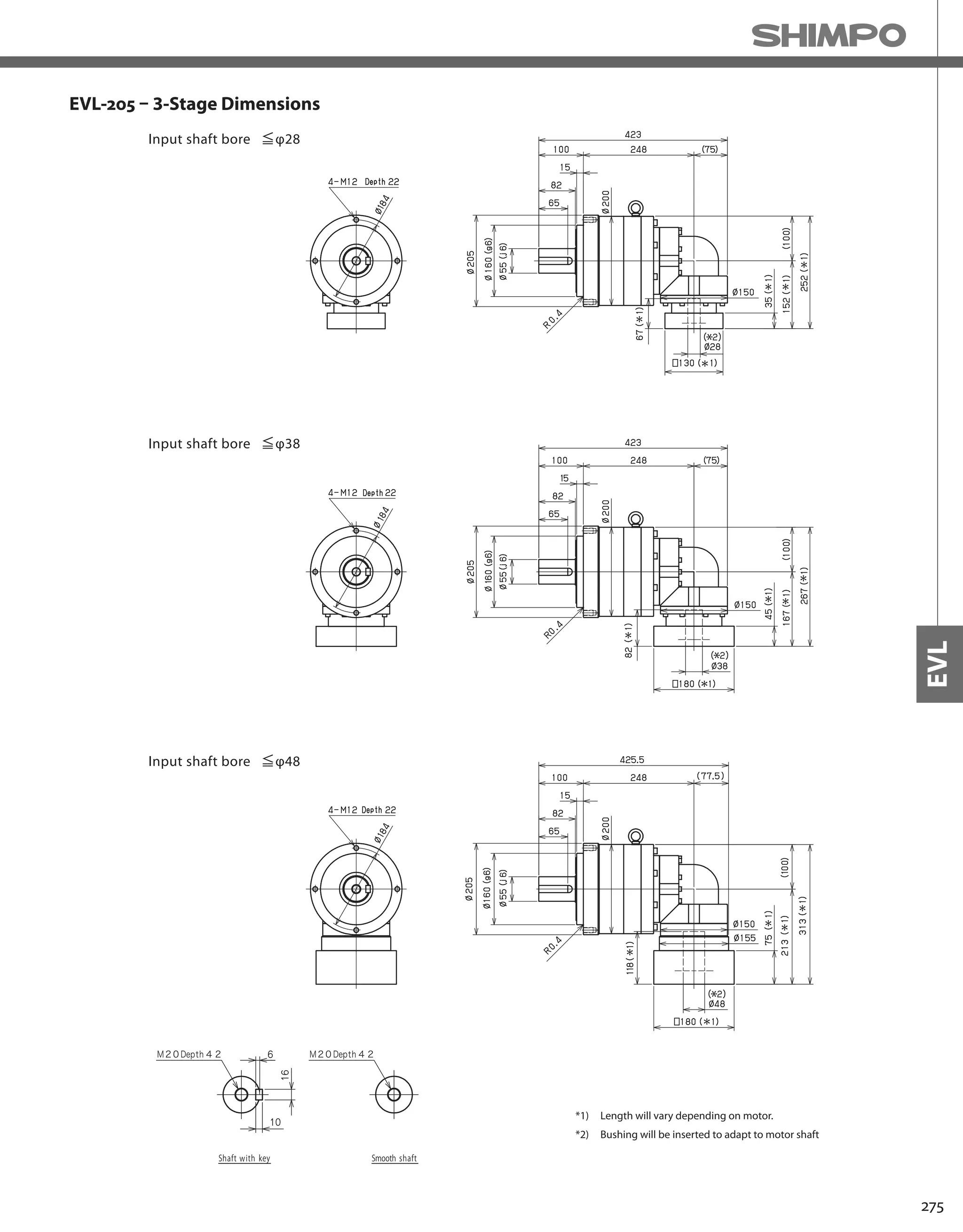

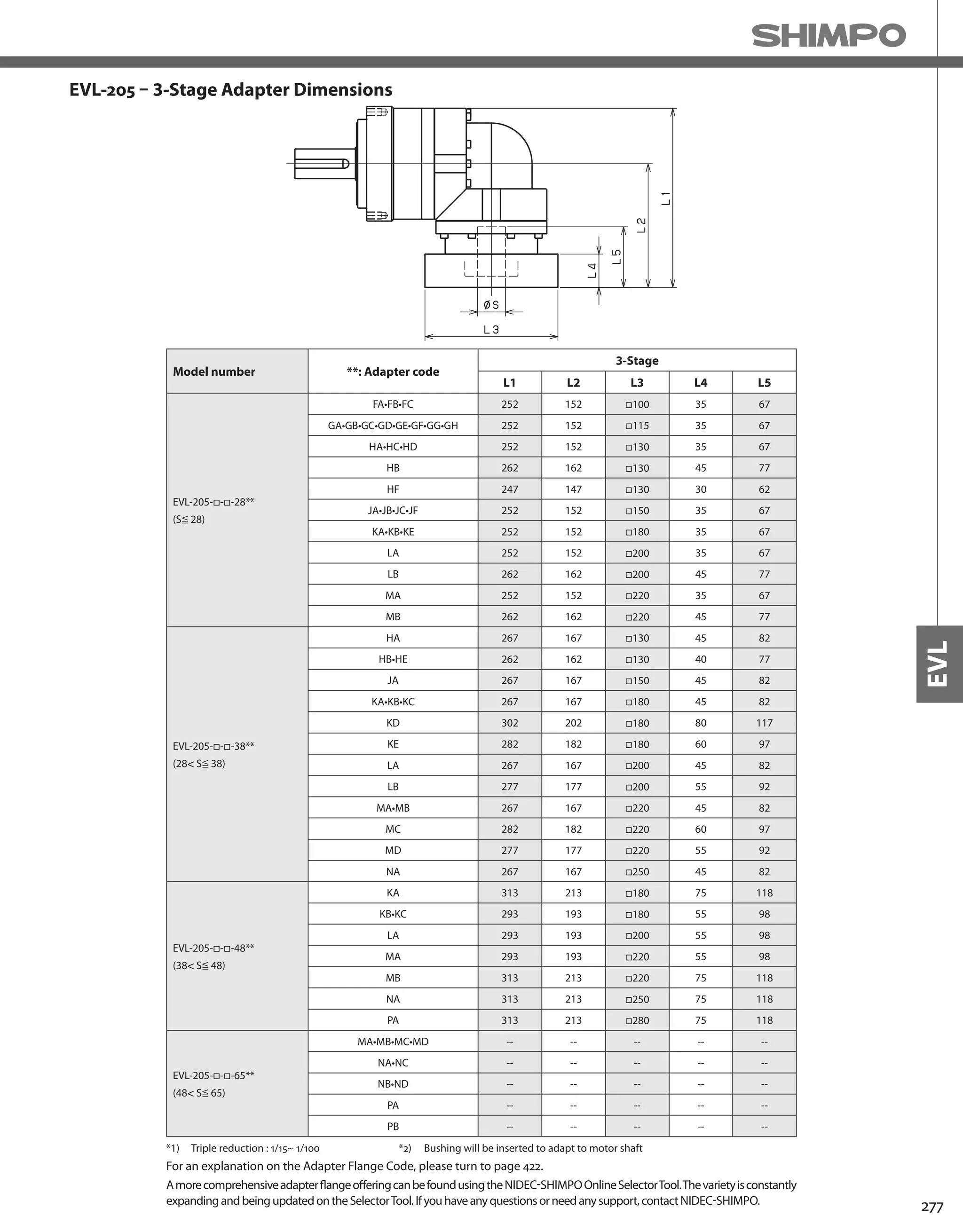
![278
EVL-SERIES Right-angle shaft
EVL-235 – 2-Stage Specifications
EVL-235 – 3-Stage Specifications
Frame Size 235
Stage 2-Stage
Ratio Units Note 3 4 5 6 7 8 9 10
Nominal Output Torque [Nm] *1 575 765 960 1150 1200 1200 800 800
Maximum Acceleration Torque [Nm] *2 1015 1355 1695 1840 1840 1760 1520 1280
Emergency Stop Torque [Nm] *3 2500 3300 4000 4500 4500 4500 3600 3600
Nominal Input Speed [rpm] *4 1000
Maximum Input Speed [rpm] *5 2000
No Load Running Torque [Nm] *6 14.5
Permitted Radial Load [N] *7 5800 6400 6900 7300 7700 8000 8400 8700
Permitted Axial Load [N] *8 6400 7200 7900 8600 9200 9700 10000 11000
Maximum Radial Load [N] *9 15000
Maximum Axial Load [N] *10 14000
Moment of Inertia (≤Ø 38) [kgcm2] -- -- -- -- -- -- -- -- --
Moment of Inertia (≤Ø 48) [kgcm2] -- 148.00 122.90 113.30 108.10 104.70 102.70 101.60 101.00
Moment of Inertia (≤ Ø 65) [kgcm2] -- 223.20 198.10 188.60 183.30 180.00 178.00 176.80 176.20
Efficiency [%] *11 93
Torsional Rigidity [Nm/arcmin] *12 400
Maximum Torsional Backlash [Arc-min] -- ≤ 8
Noise Level [dB] *13 ≤ 85
Protection Class -- *14 IP54 (IP65)
Ambient Temperature [°C] -- 0-40
Permitted Housing Temperature [°C] -- 90
Weight [kg] *15 68
Frame Size 235
Stage 3-Stage
Ratio Units Note 15 16 20 25 28 30 35 40
Nominal Output Torque [Nm] *1 800 1200 1200 1200 1200 800 1200 1200
Maximum Acceleration Torque [Nm] *2 1280 1840 1840 1840 1840 1280 1840 1840
Emergency Stop Torque [Nm] *3 3600 4500 4500 4500 4500 3600 4500 4500
Nominal Input Speed [rpm] *4 1000
Maximum Input Speed [rpm] *5 2000
No Load Running Torque [Nm] *6 10.2
Permitted Radial Load [N] *7 9900 10000 11000 12000 12000 13000 13000 14000
Permitted Axial Load [N] *8 13000 13000 14000 14000 14000 14000 14000 14000
Maximum Radial Load [N] *9 15000
Maximum Axial Load [N] *10 14000
Moment of Inertia (≤Ø 38) [kgcm2] -- 36.32 37.24 35.75 35.47 36.39 34.39 35.21 34.25
Moment of Inertia (≤Ø 48) [kgcm2] -- 66.14 67.06 65.57 65.28 66.21 64.21 65.03 64.07
Moment of Inertia (≤ Ø 65) [kgcm2] -- -- -- -- -- -- -- -- --
Efficiency [%] *11 88
Torsional Rigidity [Nm/arcmin] *12 400
Maximum Torsional Backlash [Arc-min] -- ≤ 11
Noise Level [dB] *13 ≤ 85
Protection Class -- *14 IP54 (IP65)
Ambient Temperature [°C] -- 0-40
Permitted Housing Temperature [°C] -- 90
Weight [kg] *15 70](https://image.slidesharecdn.com/shimpohighprecisioncatalog-140807090507-phpapp01/75/Shimpo-high-precision-catalog-280-2048.jpg)
![279
EVL
EVL-235 – 3-Stage Specifications
Frame Size 235
Stage 3-Stage
Ratio Units Note 45 50 60 70 80 90 100
Nominal Output Torque [Nm] *1 800 1200 1200 1200 1200 800 800
Maximum Acceleration Torque [Nm] *2 1040 1840 1840 1840 1440 1040 960
Emergency Stop Torque [Nm] *3 3600 4500 4500 4500 4500 3600 3600
Nominal Input Speed [rpm] *4 1000
Maximum Input Speed [rpm] *5 2000
No Load Running Torque [Nm] *6 10.2
Permitted Radial Load [N] *7 14000 15000 15000 15000 15000 15000 15000
Permitted Axial Load [N] *8 14000 14000 14000 14000 14000 14000 14000
Maximum Radial Load [N] *9 15000
Maximum Axial Load [N] *10 14000
Moment of Inertia (≤Ø 38) [kgcm2] -- 35.10 34.18 34.14 34.11 34.10 34.09 34.08
Moment of Inertia (≤Ø 48) [kgcm2] -- 64.92 63.99 63.95 63.93 63.91 63.90 63.90
Moment of Inertia (≤ Ø 65) [kgcm2] -- -- -- -- -- -- -- --
Efficiency [%] *11 88
Torsional Rigidity [Nm/arcmin] *12 400
Maximum Torsional Backlash [Arc-min] -- ≤ 11
Noise Level [dB] *13 ≤ 85
Protection Class -- *14 IP54 (IP65)
Ambient Temperature [°C] -- 0-40
Permitted Housing Temperature [°C] -- 90
Weight [kg] *15 70
*1) At nominal input speed, service life is 20,000 hours
*2) The maximum torque when starting or stopping operation
*3) The maximum torque allowed under a stress situation (Permitted 1,000 times during service life)
*4) The average input speed
*5) The maximum intermittent input speed
*6) This is the torque at no load applied on the input shaft. The input speed is 1000 rpm for EVL235
*7) At this load and nominal input speed, service life will be 20,000 hours. (The radial load applied to the output side bearing)
*8) At this load and nominal input speed, service life will be 20,000 hours. (The axial load applied to the output shaft center)
*9) The maximum radial load that the reducer can accept
*10) The maximum axial load that the reducer can accept
*11) The efficiency at the nominal torque rating
*12) This does not include the lost motion
*13) Contact NIDEC-SHIMPO for the testing conditions and environment
*14) IP65 (wash-down) is available as an option. Contact NIDEC-SHIMPO for more details and our food grade options
*15) The weight may vary slightly between models](https://image.slidesharecdn.com/shimpohighprecisioncatalog-140807090507-phpapp01/75/Shimpo-high-precision-catalog-281-2048.jpg)


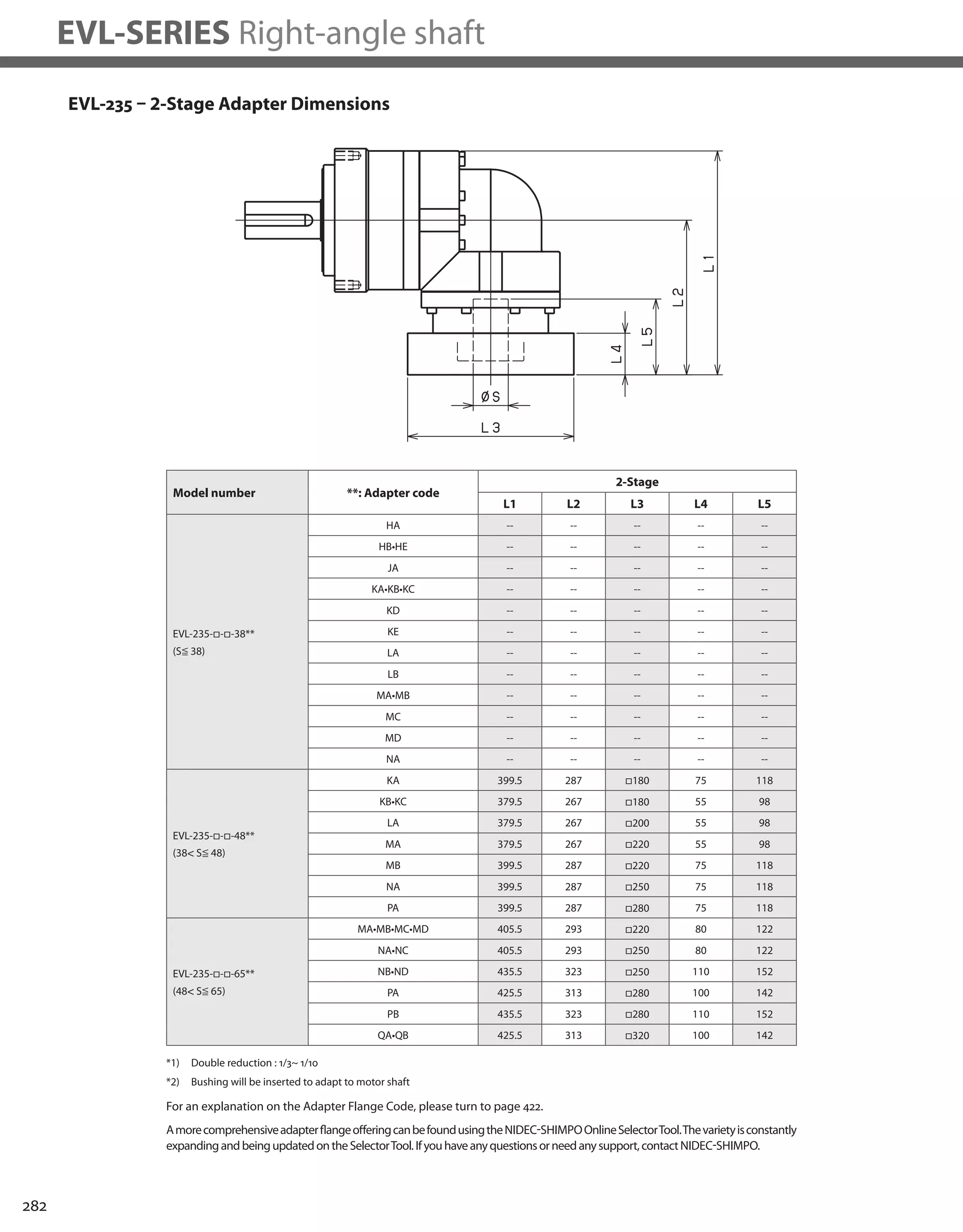


![288
EVB-SERIES Right-angle shaft
Frame Size 060
Stage 2-Stage
Ratio Unit Note 3 4 5 6 7 8 9 10
Nominal Output Torque [Nm] *1 12 16 22 24 24 24 16 16
Maximum Acceleration Torque [Nm] *2 24 32 40 45 45 45 32 32
Emergency Stop Torque [Nm] *3 50 65 80 90 90 90 65 65
Nominal Input Speed [rpm] *4 3000
Maximum Input Speed [rpm] *5 6000
No Load Running Torque [Nm] *6 0.33
Permitted Radial Load [N] *7 430 470 510 540 570 600 620 640
Permitted Axial Load [N] *8 310 360 390 430 460 480 510 530
Maximum Radial Load [N] *9 1200
Maximum Axial Load [N] *10 1100
Moment of Inertia (≤ Ø 8) [kgcm2] -- 0.310 0.270 0.250 0.240 0.230 0.230 0.230 0.230
Moment of Inertia (≤ Ø 14) [kgcm2] -- 0.390 0.340 0.320 0.310 0.310 0.310 0.300 0.300
Moment of Inertia (≤ Ø 19) [kgcm2] -- 0.580 0.530 0.510 0.500 0.500 0.500 0.490 0.490
Efficiency [%] *11 93
Torsional Rigidity [Nm/arc-min] *12 3
Maximum Torsional Backlash [arc-min] -- ≤ 4
Noise Level [dB] *13 80
Protection Class -- *14 IP54 (IP65)
Ambient Temperature [°C] -- 0-40
Permitted Housing Temperature [°C] -- 90
Weight [kg] *15 1.8
EVB-060 – 2-Stage Specifications
EVB-060 – 3-Stage Specifications
Frame Size 060
Stage 3-Stage
Ratio Unit Note 15 16 20 25 28 30 35 40
Nominal Output Torque [Nm] *1 16 24 24 24 24 16 24 24
Maximum Acceleration Torque [Nm] *2 32 45 45 45 45 32 45 45
Emergency Stop Torque [Nm] *3 65 90 90 90 90 65 90 90
Nominal Input Speed [rpm] *4 3000
Maximum Input Speed [rpm] *5 6000
No Load Running Torque [Nm] *6 0.20
Permitted Radial Load [N] *7 740 750 810 870 910 930 980 1000
Permitted Axial Load [N] *8 630 650 720 790 830 860 920 970
Maximum Radial Load [N] *9 1200
Maximum Axial Load [N] *10 1100
Moment of Inertia (≤ Ø 8) [kgcm2] -- 0.073 0.079 0.071 0.071 0.077 0.062 0.070 0.061
Moment of Inertia (≤ Ø 14) [kgcm2] -- 0.118 0.124 0.116 0.115 0.122 0.106 0.115 0.106
Moment of Inertia (≤ Ø 19) [kgcm2] -- -- -- -- -- -- -- -- --
Efficiency [%] *11 88
Torsional Rigidity [Nm/arc-min] *12 3
Maximum Torsional Backlash [arc-min] -- ≤ 7
Noise Level [dB] *13 80
Protection Class -- *14 IP54 (IP65)
Ambient Temperature [°C] -- 0-40
Permitted Housing Temperature [°C] -- 90
Weight [kg] *15 1.6](https://image.slidesharecdn.com/shimpohighprecisioncatalog-140807090507-phpapp01/75/Shimpo-high-precision-catalog-290-2048.jpg)
![289
EVB
EVB-060 – 3-Stage Specifications
Frame Size 060
Stage 3-Stage
Ratio Unit Note 45 50 60 70 80 90 100
Nominal Output Torque [Nm] *1 16 24 24 24 24 16 16
Maximum Acceleration Torque [Nm] *2 32 45 45 45 45 32 32
Emergency Stop Torque [Nm] *3 65 90 90 90 90 65 65
Nominal Input Speed [rpm] *4 3000
Maximum Input Speed [rpm] *5 6000
No Load Running Torque [Nm] *6 0.20
Permitted Radial Load [N] *7 1100 1100 1200 1200 1200 1200 1200
Permitted Axial Load [N] *8 1000 1100 1100 1100 1100 1100 1100
Maximum Radial Load [N] *9 1200
Maximum Axial Load [N] *10 1100
Moment of Inertia (≤ Ø 8) [kgcm2] -- 0.070 0.061 0.061 0.061 0.061 0.061 0.061
Moment of Inertia (≤ Ø 14) [kgcm2] -- 0.115 0.106 0.106 0.105 0.105 0.105 0.105
Moment of Inertia (≤ Ø 19) [kgcm2] -- -- -- -- -- -- -- --
Efficiency [%] *11 88
Torsional Rigidity [Nm/arc-min] *12 3
Maximum Torsional Backlash [arc-min] -- ≤ 7
Noise Level [dB] *13 80
Protection Class -- *14 IP54 (IP65)
Ambient Temperature [°C] -- 0-40
Permitted Housing Temperature [°C] -- 90
Weight [kg] *15 1.6
*1) At nominal input speed, service life is 20,000 hours
*2) The maximum torque when starting or stopping operation
*3) The maximum torque allowed under a stress situation (Permitted 1,000 times during service life)
*4) The average input speed
*5) The maximum intermittent input speed
*6) This is the torque at no load applied on the input shaft. The input speed is 3000 rpm for EVB060
*7) At this load and nominal input speed, service life will be 20,000 hours. (The radial load applied to the output side bearing)
*8) At this load and nominal input speed, service life will be 20,000 hours. (The axial load applied to the output shaft center)
*9) The maximum radial load that the reducer can accept
*10) The maximum axial load that the reducer can accept
*11) The efficiency at the nominal torque rating
*12) This does not include the lost motion
*13) Contact NIDEC-SHIMPO for the testing conditions and environment
*14) IP65 (wash-down) is available as an option. Contact NIDEC-SHIMPO for more details and our food grade options
*15) The weight may vary slightly between models](https://image.slidesharecdn.com/shimpohighprecisioncatalog-140807090507-phpapp01/75/Shimpo-high-precision-catalog-291-2048.jpg)


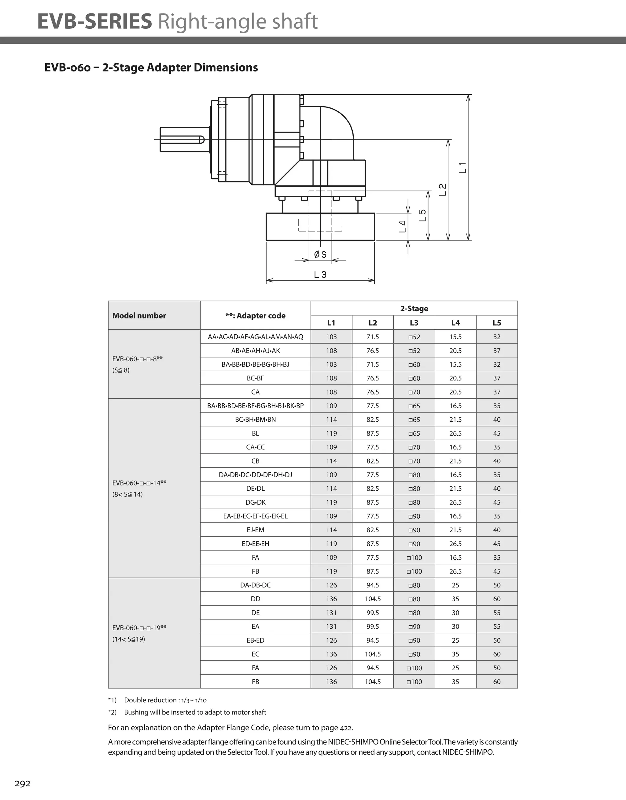
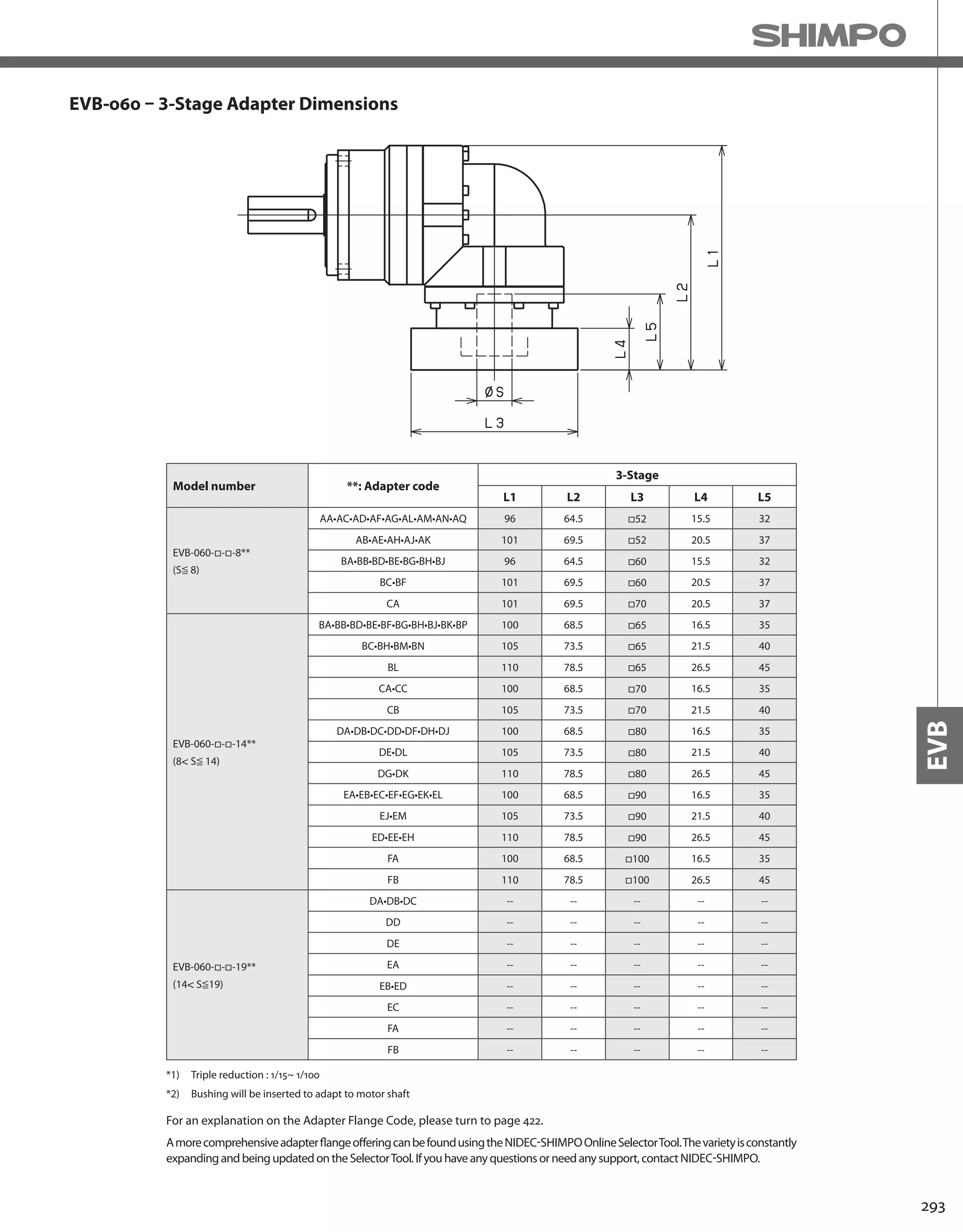
![294
EVB-SERIES Right-angle shaft
EVB-090 – 2-Stage Specifications
EVB-090 – 3-Stage Specifications
Frame Size 090
Stage 2-Stage
Ratio Unit Note 3 4 5 6 7 8 9 10
Nominal Output Torque [Nm] *1 45 60 65 65 65 65 45 45
Maximum Acceleration Torque [Nm] *2 65 90 90 90 90 90 65 65
Emergency Stop Torque [Nm] *3 130 170 220 220 220 220 170 170
Nominal Input Speed [rpm] *4 3000
Maximum Input Speed [rpm] *5 6000
No Load Running Torque [Nm] *6 1.13
Permitted Radial Load [N] *7 810 890 960 1000 1100 1100 1200 1200
Permitted Axial Load [N] *8 930 1100 1200 1300 1300 1400 1500 1600
Maximum Radial Load [N] *9 2400
Maximum Axial Load [N] *10 2200
Moment of Inertia (≤ Ø 8) [kgcm2] -- -- -- -- -- -- -- -- --
Moment of Inertia (≤ Ø 14) [kgcm2] -- 2.120 1.890 1.800 1.760 1.730 1.710 1.700 1.690
Moment of Inertia (≤ Ø 19) [kgcm2] -- 2.450 2.220 2.130 2.090 2.060 2.040 2.030 2.020
Moment of Inertia (≤ Ø 28) [kgcm2] -- 4.570 4.350 4.260 4.210 4.180 4.170 4.160 4.150
Efficiency [%] *11 93
Torsional Rigidity [Nm/arc-min] *12 10
Maximum Torsional Backlash [arc-min] -- ≤ 4
Noise Level [dB] *13 80
Protection Class -- *14 IP54 (IP65)
Ambient Temperature [°C] -- 0-40
Permitted Housing Temperature [°C] -- 90
Weight [kg] *15 5.1
Frame Size 090
Stage 3-Stage
Ratio Unit Note 15 16 20 25 28 30 35 40
Nominal Output Torque [Nm] *1 45 65 65 65 65 45 65 65
Maximum Acceleration Torque [Nm] *2 65 110 110 110 110 65 110 110
Emergency Stop Torque [Nm] *3 170 220 220 220 220 170 220 220
Nominal Input Speed [rpm] *4 3000
Maximum Input Speed [rpm] *5 6000
No Load Running Torque [Nm] *6 0.55
Permitted Radial Load [N] *7 1400 1400 1500 1600 1700 1700 1800 1900
Permitted Axial Load [N] *8 1900 1900 2100 2200 2200 2200 2200 2200
Maximum Radial Load [N] *9 2400
Maximum Axial Load [N] *10 2200
Moment of Inertia (≤ Ø 8) [kgcm2] -- 0.340 0.380 0.330 0.320 0.370 0.250 0.320 0.250
Moment of Inertia (≤ Ø 14) [kgcm2] -- 0.410 0.460 0.400 0.400 0.450 0.330 0.400 0.320
Moment of Inertia (≤ Ø 19) [kgcm2] -- 0.600 0.650 0.590 0.590 0.640 0.510 0.590 0.510
Moment of Inertia (≤ Ø 28) [kgcm2] -- -- -- -- -- -- -- -- --
Efficiency [%] *11 88
Torsional Rigidity [Nm/arc-min] *12 10
Maximum Torsional Backlash [arc-min] -- ≤ 7
Noise Level [dB] *13 80
Protection Class -- *14 IP54 (IP65)
Ambient Temperature [°C] -- 0-40
Permitted Housing Temperature [°C] -- 90
Weight [kg] *15 4.4](https://image.slidesharecdn.com/shimpohighprecisioncatalog-140807090507-phpapp01/75/Shimpo-high-precision-catalog-296-2048.jpg)
![295
EVB
EVB-090 – 3-Stage Specifications
Frame Size 090
Stage 3-Stage
Ratio Unit Note 45 50 60 70 80 90 100
Nominal Output Torque [Nm] *1 45 65 65 65 65 45 45
Maximum Acceleration Torque [Nm] *2 65 110 110 110 110 65 65
Emergency Stop Torque [Nm] *3 170 220 220 220 220 170 170
Nominal Input Speed [rpm] *4 3000
Maximum Input Speed [rpm] *5 6000
No Load Running Torque [Nm] *6 0.55
Permitted Radial Load [N] *7 2000 2100 2200 2300 2400 2400 2400
Permitted Axial Load [N] *8 2200 2200 2200 2200 2200 2200 2200
Maximum Radial Load [N] *9 2400
Maximum Axial Load [N] *10 2200
Moment of Inertia (≤ Ø 8) [kgcm2] -- 0.320 0.250 0.250 0.250 0.250 0.250 0.250
Moment of Inertia (≤ Ø 14) [kgcm2] -- 0.390 0.320 0.320 0.320 0.320 0.320 0.320
Moment of Inertia (≤ Ø 19) [kgcm2] -- 0.580 0.510 0.510 0.510 0.510 0.510 0.510
Moment of Inertia (≤ Ø 28) [kgcm2] -- -- -- -- -- -- -- --
Efficiency [%] *11 88
Torsional Rigidity [Nm/arc-min] *12 10
Maximum Torsional Backlash [arc-min] -- ≤ 7
Noise Level [dB] *13 80
Protection Class -- *14 IP54 (IP65)
Ambient Temperature [°C] -- 0-40
Permitted Housing Temperature [°C] -- 90
Weight [kg] *15 4.4
*1) At nominal input speed, service life is 20,000 hours
*2) The maximum torque when starting or stopping operation
*3) The maximum torque allowed under a stress situation (Permitted 1,000 times during service life)
*4) The average input speed
*5) The maximum intermittent input speed
*6) This is the torque at no load applied on the input shaft. The input speed is 3000 rpm for EVB090
*7) At this load and nominal input speed, service life will be 20,000 hours. (The radial load applied to the output side bearing)
*8) At this load and nominal input speed, service life will be 20,000 hours. (The axial load applied to the output shaft center)
*9) The maximum radial load that the reducer can accept
*10) The maximum axial load that the reducer can accept
*11) The efficiency at the nominal torque rating
*12) This does not include the lost motion
*13) Contact NIDEC-SHIMPO for the testing conditions and environment
*14) IP65 (wash-down) is available as an option. Contact NIDEC-SHIMPO for more details and our food grade options
*15) The weight may vary slightly between models](https://image.slidesharecdn.com/shimpohighprecisioncatalog-140807090507-phpapp01/75/Shimpo-high-precision-catalog-297-2048.jpg)

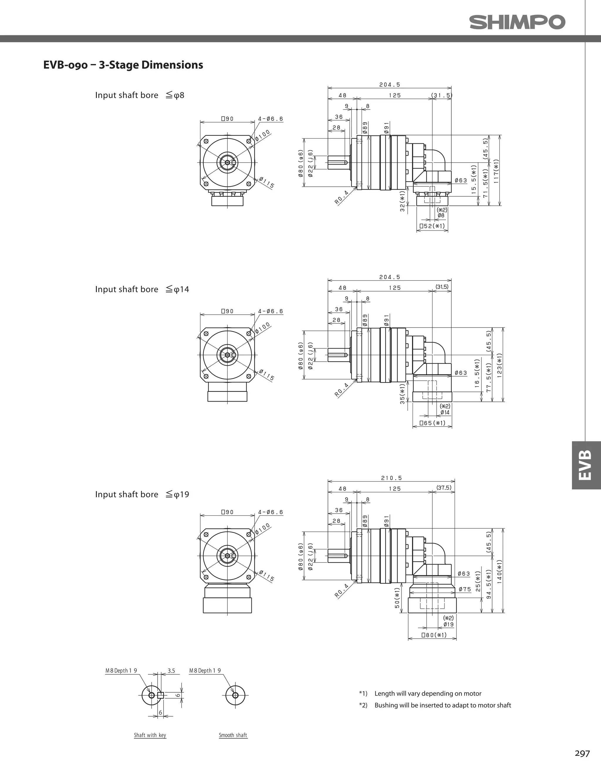
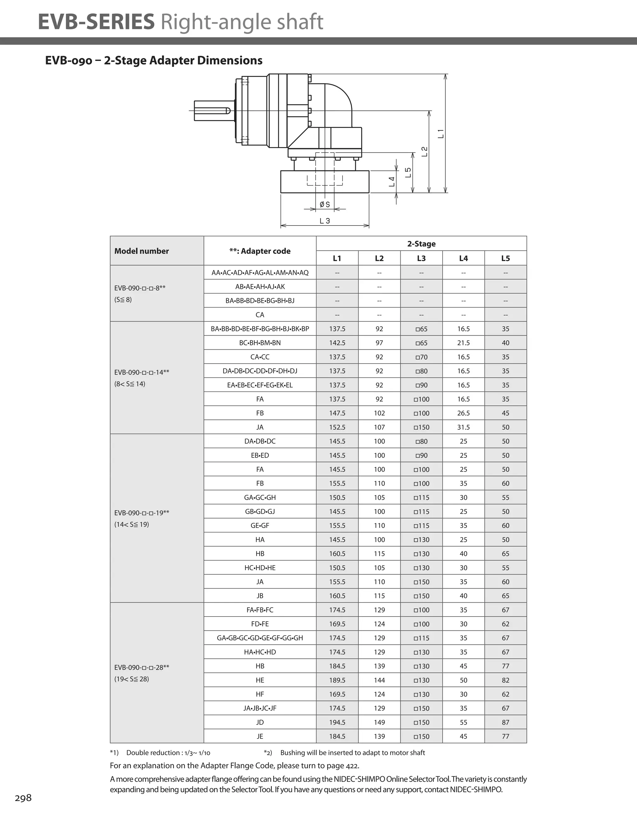
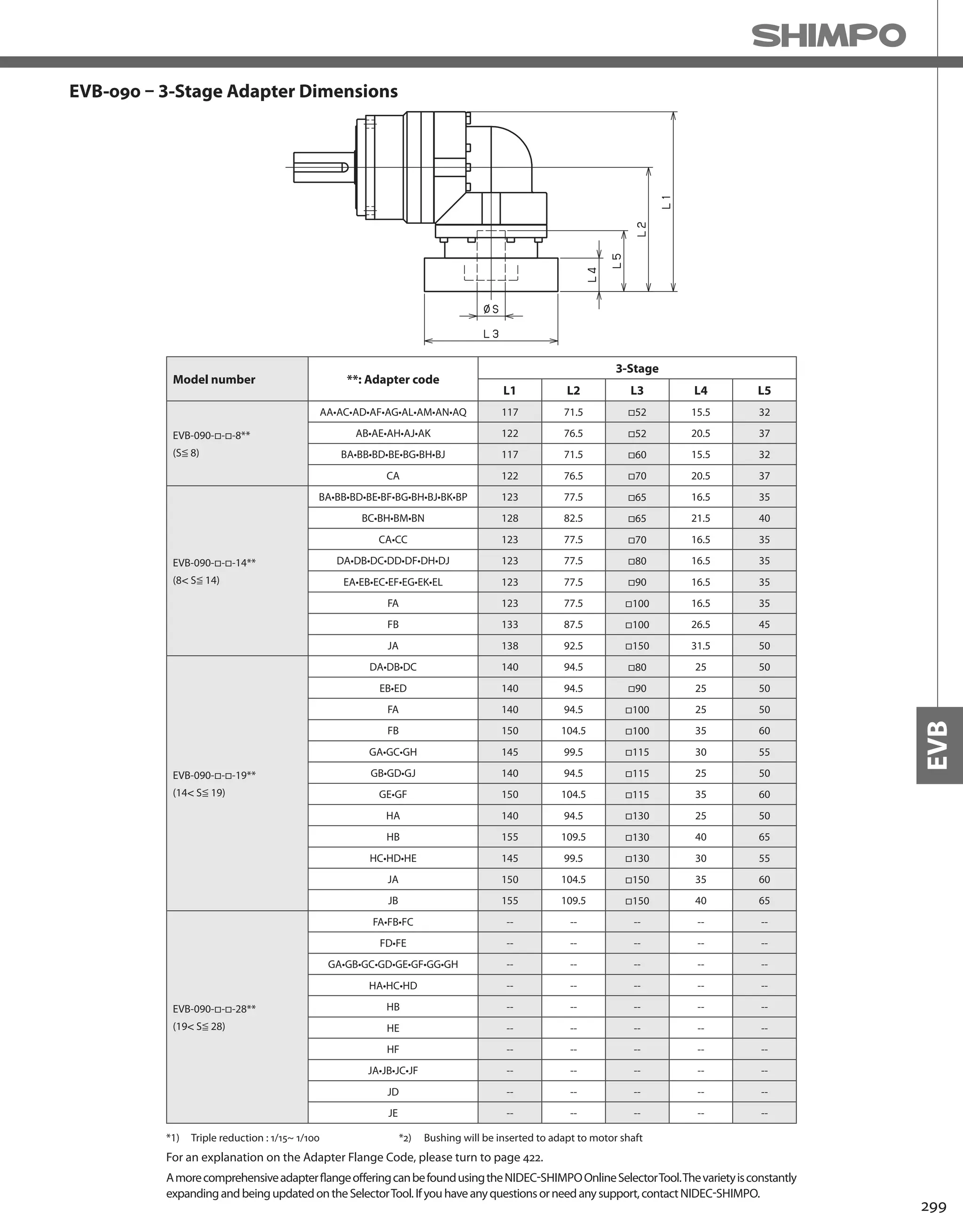
![300
EVB-SERIES Right-angle shaft
EVB-115 – 2-Stage Specifications
EVB-115 – 3-Stage Specifications
Frame Size 115
Stage 2-Stage
Ratio Unit Note 3 4 5 6 7 8 9 10
Nominal Output Torque [Nm] *1 75 100 120 150 150 150 110 110
Maximum Acceleration Torque [Nm] *2 150 200 240 300 300 300 200 200
Emergency Stop Torque [Nm] *3 320 430 500 550 550 550 450 450
Nominal Input Speed [rpm] *4 3000
Maximum Input Speed [rpm] *5 6000
No Load Running Torque [Nm] *6 1.88
Permitted Radial Load [N] *7 1300 1500 1600 1700 1800 1900 1900 2000
Permitted Axial Load [N] *8 1500 1700 1900 2000 2100 2300 2400 2500
Maximum Radial Load [N] *9 4300
Maximum Axial Load [N] *10 3900
Moment of Inertia (≤ Ø 14) [kgcm2] -- -- -- -- -- -- -- -- --
Moment of Inertia (≤ Ø 19) [kgcm2] -- 6.740 5.490 5.020 4.770 4.650 4.550 4.490 4.460
Moment of Inertia (≤ Ø 28) [kgcm2] -- 8.340 7.080 6.610 6.360 6.240 6.140 6.080 6.050
Moment of Inertia (≤ Ø 38) [kgcm2] -- 15.410 14.150 13.690 13.430 13.310 13.220 13.160 13.120
Efficiency [%] *11 93
Torsional Rigidity [Nm/arc-min] *12 31
Maximum Torsional Backlash [arc-min] -- ≤ 4
Noise Level [dB] *13 85
Protection Class -- *14 IP54 (IP65)
Ambient Temperature [°C] -- 0-40
Permitted Housing Temperature [°C] -- 90
Weight [kg] *15 10.4
Frame Size 115
Stage 3-Stage
Ratio Unit Note 15 16 20 25 28 30 35 40
Nominal Output Torque [Nm] *1 110 130 150 150 150 110 150 150
Maximum Acceleration Torque [Nm] *2 200 260 300 300 300 200 300 300
Emergency Stop Torque [Nm] *3 450 550 550 550 550 450 550 550
Nominal Input Speed [rpm] *4 3000
Maximum Input Speed [rpm] *5 6000
No Load Running Torque [Nm] *6 1.11
Permitted Radial Load [N] *7 2300 2300 2500 2700 2800 2900 3000 3200
Permitted Axial Load [N] *8 3000 3100 3400 3700 3900 3900 3900 3900
Maximum Radial Load [N] *9 3900
Maximum Axial Load [N] *10 3900
Moment of Inertia (≤ Ø 14) [kgcm2] -- 2.250 2.460 2.200 2.180 2.400 1.870 2.160 1.860
Moment of Inertia (≤ Ø 19) [kgcm2] -- 2.580 2.790 2.530 2.510 2.730 2.200 2.490 2.190
Moment of Inertia (≤ Ø 28) [kgcm2] -- 4.700 4.910 4.650 4.640 4.860 4.330 4.620 4.320
Moment of Inertia (≤ Ø 38) [kgcm2] -- -- -- -- -- -- -- -- --
Efficiency [%] *11 88
Torsional Rigidity [Nm/arc-min] *12 31
Maximum Torsional Backlash [arc-min] -- ≤ 7
Noise Level [dB] *13 85
Protection Class -- *14 IP54 (IP65)
Ambient Temperature [°C] -- 0-40
Permitted Housing Temperature [°C] -- 90
Weight [kg] *15 10.1](https://image.slidesharecdn.com/shimpohighprecisioncatalog-140807090507-phpapp01/75/Shimpo-high-precision-catalog-302-2048.jpg)
![301
EVB
EVB-115 – 3-Stage Specifications
Frame Size 115
Stage 3-Stage
Ratio Unit Note 45 50 60 70 80 90 100
Nominal Output Torque [Nm] *1 110 150 150 150 150 110 110
Maximum Acceleration Torque [Nm] *2 200 300 300 300 300 200 200
Emergency Stop Torque [Nm] *3 450 550 550 550 550 450 450
Nominal Input Speed [rpm] *4 3000
Maximum Input Speed [rpm] *5 6000
No Load Running Torque [Nm] *6 1.11
Permitted Radial Load [N] *7 3300 3400 3600 3800 4000 4200 4300
Permitted Axial Load [N] *8 3900 3900 3900 3900 3900 3900 3900
Maximum Radial Load [N] *9 4300
Maximum Axial Load [N] *10 3900
Moment of Inertia (≤ Ø 14) [kgcm2] -- 2.150 1.860 1.850 1.850 1.850 1.850 1.850
Moment of Inertia (≤ Ø 19) [kgcm2] -- 2.480 2.190 2.180 2.180 2.180 2.180 2.180
Moment of Inertia (≤ Ø 28) [kgcm2] -- 4.610 4.310 4.310 4.310 4.310 4.310 4.310
Moment of Inertia (≤ Ø 38) [kgcm2] -- -- -- -- -- -- -- --
Efficiency [%] *11 88
Torsional Rigidity [Nm/arc-min] *12 31
Maximum Torsional Backlash [arc-min] -- ≤ 7
Noise Level [dB] *13 85
Protection Class -- *14 IP54 (IP65)
Ambient Temperature [°C] -- 0-40
Permitted Housing Temperature [°C] -- 90
Weight [kg] *15 10.1
*1) At nominal input speed, service life is 20,000 hours
*2) The maximum torque when starting or stopping operation
*3) The maximum torque allowed under a stress situation (Permitted 1,000 times during service life)
*4) The average input speed
*5) The maximum intermittent input speed
*6) This is the torque at no load applied on the input shaft. The input speed is 3000 rpm for EVB115
*7) At this load and nominal input speed, service life will be 20,000 hours. (The radial load applied to the output side bearing)
*8) At this load and nominal input speed, service life will be 20,000 hours. (The axial load applied to the output shaft center)
*9) The maximum radial load that the reducer can accept
*10) The maximum axial load that the reducer can accept
*11) The efficiency at the nominal torque rating
*12) This does not include the lost motion
*13) Contact NIDEC-SHIMPO for the testing conditions and environment
*14) IP65 (wash-down) is available as an option. Contact NIDEC-SHIMPO for more details and our food grade options
*15) The weight may vary slightly between models](https://image.slidesharecdn.com/shimpohighprecisioncatalog-140807090507-phpapp01/75/Shimpo-high-precision-catalog-303-2048.jpg)
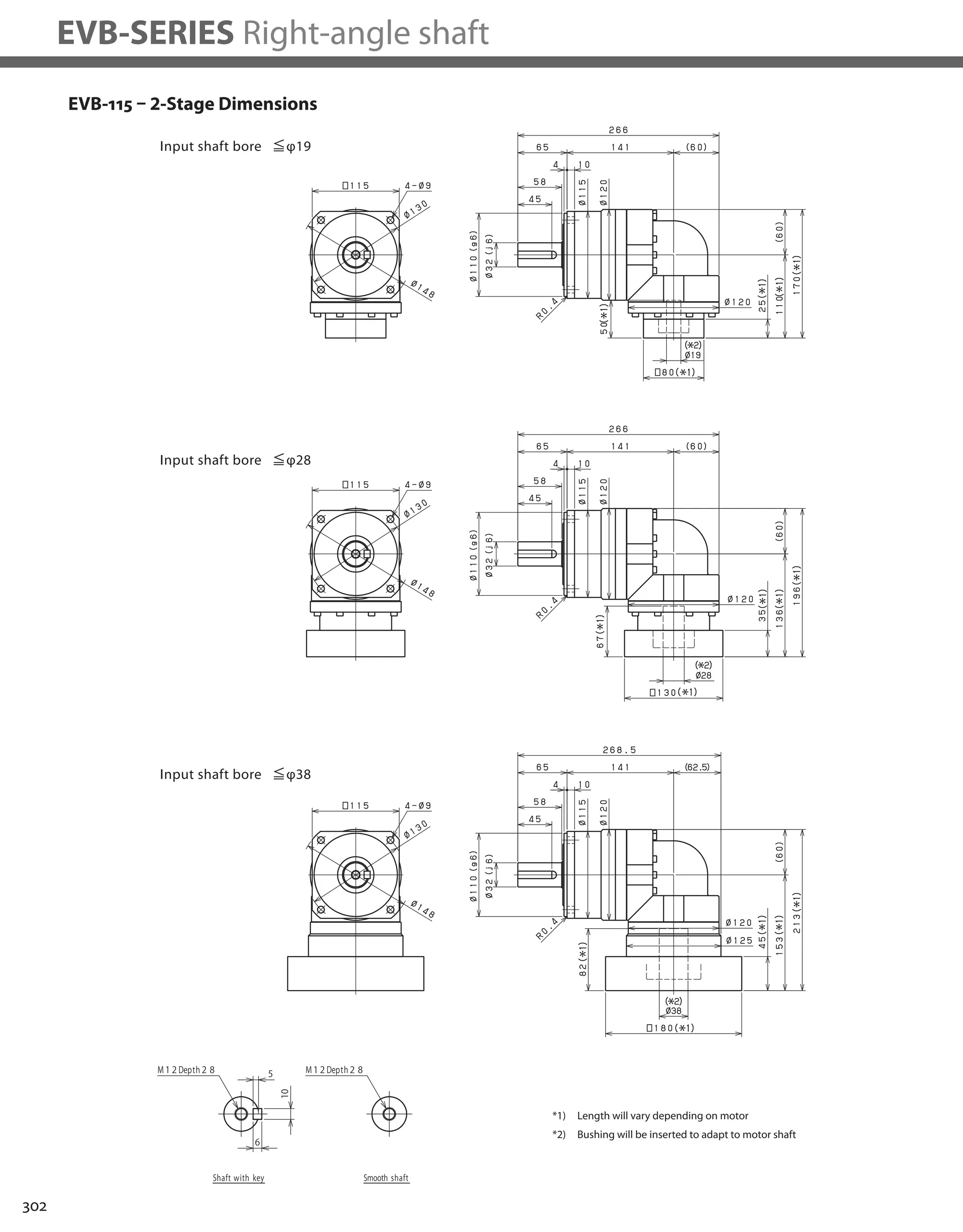
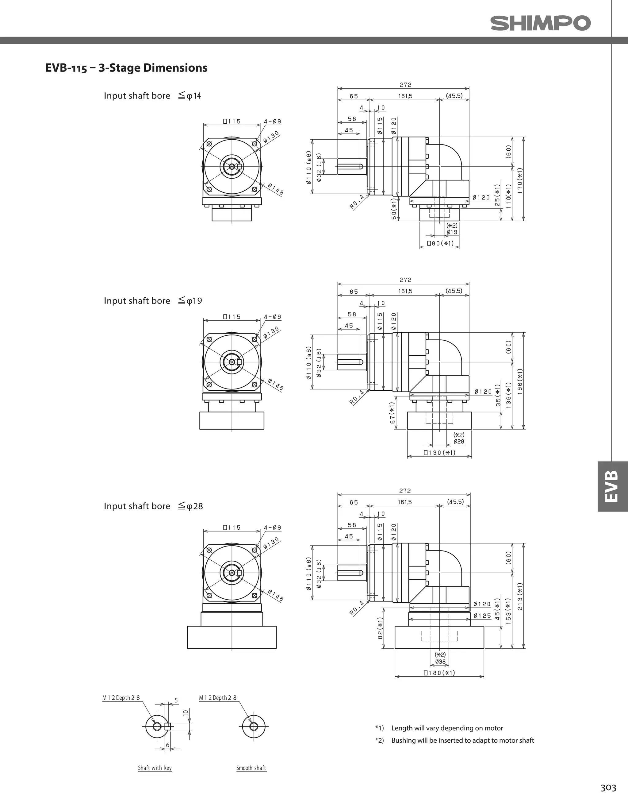
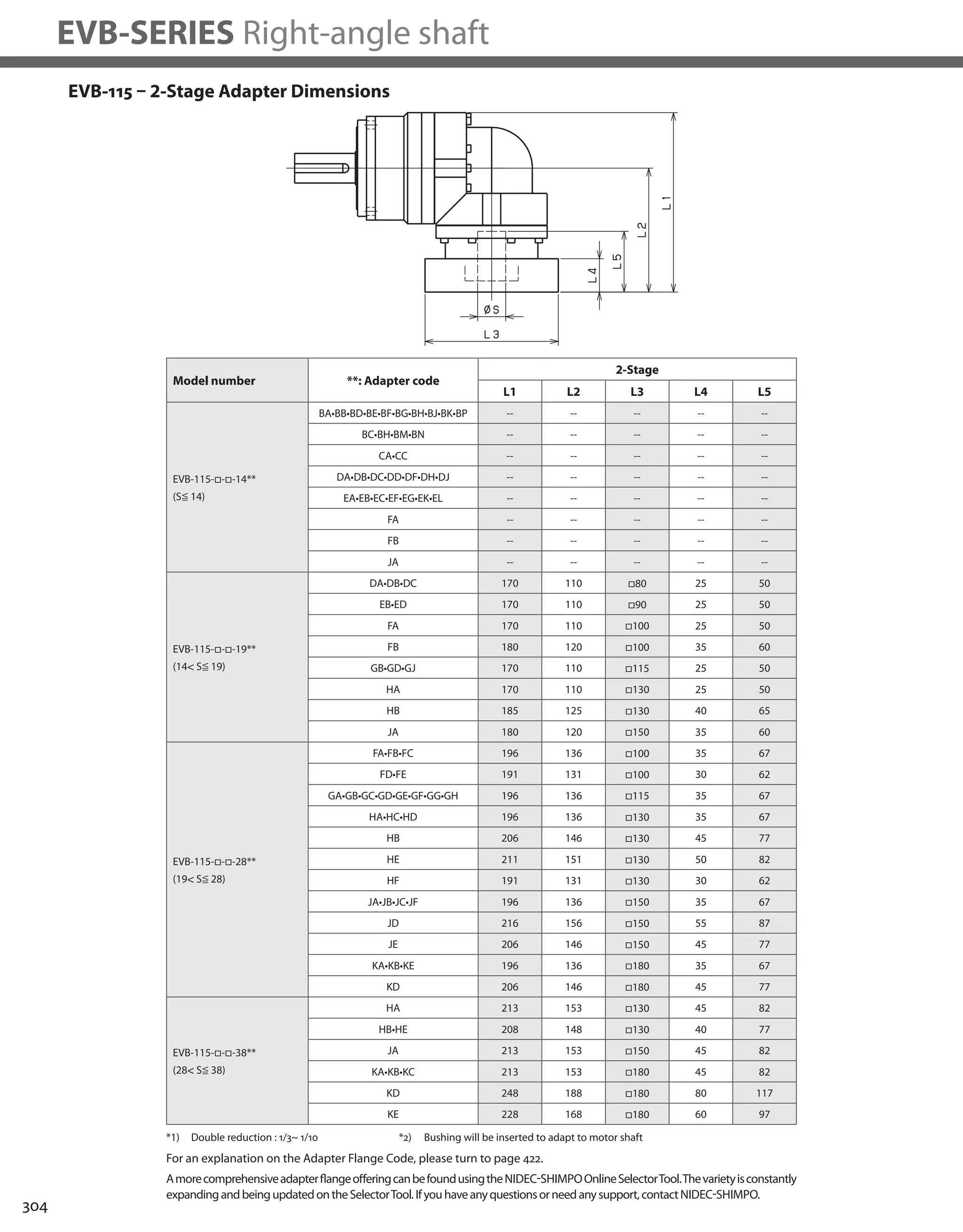

![306
EVB-SERIES Right-angle shaft
EVB-140 – 2-Stage Specifications
EVB-140 – 3-Stage Specifications
Frame Size 140
Stage 2-Stage
Ratio Unit Note 3 4 5 6 7 8 9 10
Nominal Output Torque [Nm] *1 130 170 200 260 300 300 200 200
Maximum Acceleration Torque [Nm] *2 260 340 400 520 600 600 400 400
Emergency Stop Torque [Nm] *3 700 950 1100 1100 1100 1100 750 750
Nominal Input Speed [rpm] *4 2000
Maximum Input Speed [rpm] *5 4000
No Load Running Torque [Nm] *6 3.26
Permitted Radial Load [N] *7 3200 3500 3800 4000 4200 4400 4600 4700
Permitted Axial Load [N] *8 2400 2700 3000 3300 3500 3700 3900 4100
Maximum Radial Load [N] *9 9100
Maximum Axial Load [N] *10 8200
Moment of Inertia (≤ Ø 19) [kgcm2] -- -- -- -- -- -- -- -- --
Moment of Inertia (≤ Ø 28) [kgcm2] -- 23.130 18.570 16.910 16.010 15.580 15.230 14.770 14.660
Moment of Inertia (≤ Ø 38) [kgcm2] -- 27.500 22.940 21.280 20.380 19.950 19.610 19.410 19.030
Moment of Inertia (≤ Ø 48) [kgcm2] -- 40.730 36.170 34.510 33.610 33.180 32.840 32.370 32.260
Efficiency [%] *11 93
Torsional Rigidity [Nm/arc-min] *12 60
Maximum Torsional Backlash [arc-min] -- ≤ 4
Noise Level [dB] *13 85
Protection Class -- *14 IP54 (IP65)
Ambient Temperature [°C] -- 0-40
Permitted Housing Temperature [°C] -- 90
Weight [kg] *15 19.1
Frame Size 140
Stage 3-Stage
Ratio Unit Note 15 16 20 25 28 30 35 40
Nominal Output Torque [Nm] *1 200 300 300 300 300 200 300 300
Maximum Acceleration Torque [Nm] *2 400 600 600 600 600 400 600 600
Emergency Stop Torque [Nm] *3 750 1100 1100 1100 1100 750 1100 1100
Nominal Input Speed [rpm] *4 2000
Maximum Input Speed [rpm] *5 4000
No Load Running Torque [Nm] *6 2.56
Permitted Radial Load [N] *7 5400 5500 6000 6400 6700 6800 7200 7500
Permitted Axial Load [N] *8 4900 5000 5500 6100 6400 6600 7000 7500
Maximum Radial Load [N] *9 9100
Maximum Axial Load [N] *10 8200
Moment of Inertia (≤ Ø 19) [kgcm2] -- 6.400 7.290 6.220 6.150 7.090 4.990 6.090 4.950
Moment of Inertia (≤ Ø 28) [kgcm2] -- 8.000 8.880 7.810 7.750 8.680 6.580 7.690 6.540
Moment of Inertia (≤ Ø 38) [kgcm2] -- 15.070 15.960 14.890 14.820 15.760 13.660 14.760 13.610
Moment of Inertia (≤ Ø 48) [kgcm2] -- -- -- -- -- -- -- -- --
Efficiency [%] *11 88
Torsional Rigidity [Nm/arc-min] *12 60
Maximum Torsional Backlash [arc-min] -- ≤ 7
Noise Level [dB] *13 85
Protection Class -- *14 IP54 (IP65)
Ambient Temperature [°C] -- 0-40
Permitted Housing Temperature [°C] -- 90
Weight [kg] *15 19.6](https://image.slidesharecdn.com/shimpohighprecisioncatalog-140807090507-phpapp01/75/Shimpo-high-precision-catalog-308-2048.jpg)
![307
EVB
EVB-140 – 3-Stage Specifications
Frame Size 140
Stage 3-Stage
Ratio Unit Note 45 50 60 70 80 90 100
Nominal Output Torque [Nm] *1 200 300 300 300 300 200 200
Maximum Acceleration Torque [Nm] *2 400 600 600 600 600 400 400
Emergency Stop Torque [Nm] *3 750 1100 1100 1100 1100 750 750
Nominal Input Speed [rpm] *4 2000
Maximum Input Speed [rpm] *5 4000
No Load Running Torque [Nm] *6 2.56
Permitted Radial Load [N] *7 7800 8100 8600 9100 9100 9100 9100
Permitted Axial Load [N] *8 7900 8200 8200 8200 8200 8200 8200
Maximum Radial Load [N] *9 9100
Maximum Axial Load [N] *10 8200
Moment of Inertia (≤ Ø 19) [kgcm2] -- 6.070 4.930 4.920 4.910 4.910 4.910 4.910
Moment of Inertia (≤ Ø 28) [kgcm2] -- 7.660 6.520 6.510 6.510 6.500 6.500 6.500
Moment of Inertia (≤ Ø 38) [kgcm2] -- 14.740 13.590 13.590 13.580 13.580 13.570 13.570
Moment of Inertia (≤ Ø 48) [kgcm2] -- -- -- -- -- -- -- --
Efficiency [%] *11 88
Torsional Rigidity [Nm/arc-min] *12 60
Maximum Torsional Backlash [arc-min] -- ≤ 7
Noise Level [dB] *13 85
Protection Class -- *14 IP54 (IP65)
Ambient Temperature [°C] -- 0-40
Permitted Housing Temperature [°C] -- 90
Weight [kg] *15 19.6
*1) At nominal input speed, service life is 20,000 hours
*2) The maximum torque when starting or stopping operation
*3) The maximum torque allowed under a stress situation (Permitted 1,000 times during service life)
*4) The average input speed
*5) The maximum intermittent input speed
*6) This is the torque at no load applied on the input shaft. The input speed is 2000 rpm for EVB140
*7) At this load and nominal input speed, service life will be 20,000 hours. (The radial load applied to the output side bearing)
*8) At this load and nominal input speed, service life will be 20,000 hours. (The axial load applied to the output shaft center)
*9) The maximum radial load that the reducer can accept
*10) The maximum axial load that the reducer can accept
*11) The efficiency at the nominal torque rating
*12) This does not include the lost motion
*13) Contact NIDEC-SHIMPO for the testing conditions and environment
*14) IP65 (wash-down) is available as an option. Contact NIDEC-SHIMPO for more details and our food grade options
*15) The weight may vary slightly between models](https://image.slidesharecdn.com/shimpohighprecisioncatalog-140807090507-phpapp01/75/Shimpo-high-precision-catalog-309-2048.jpg)
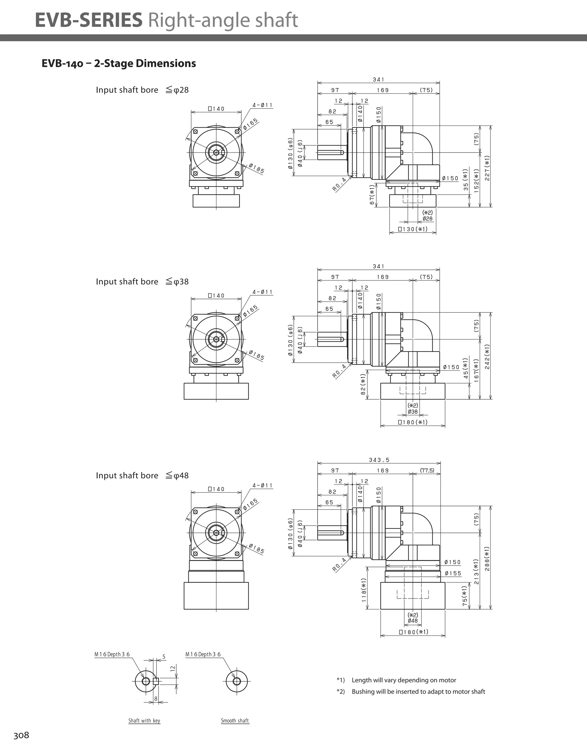
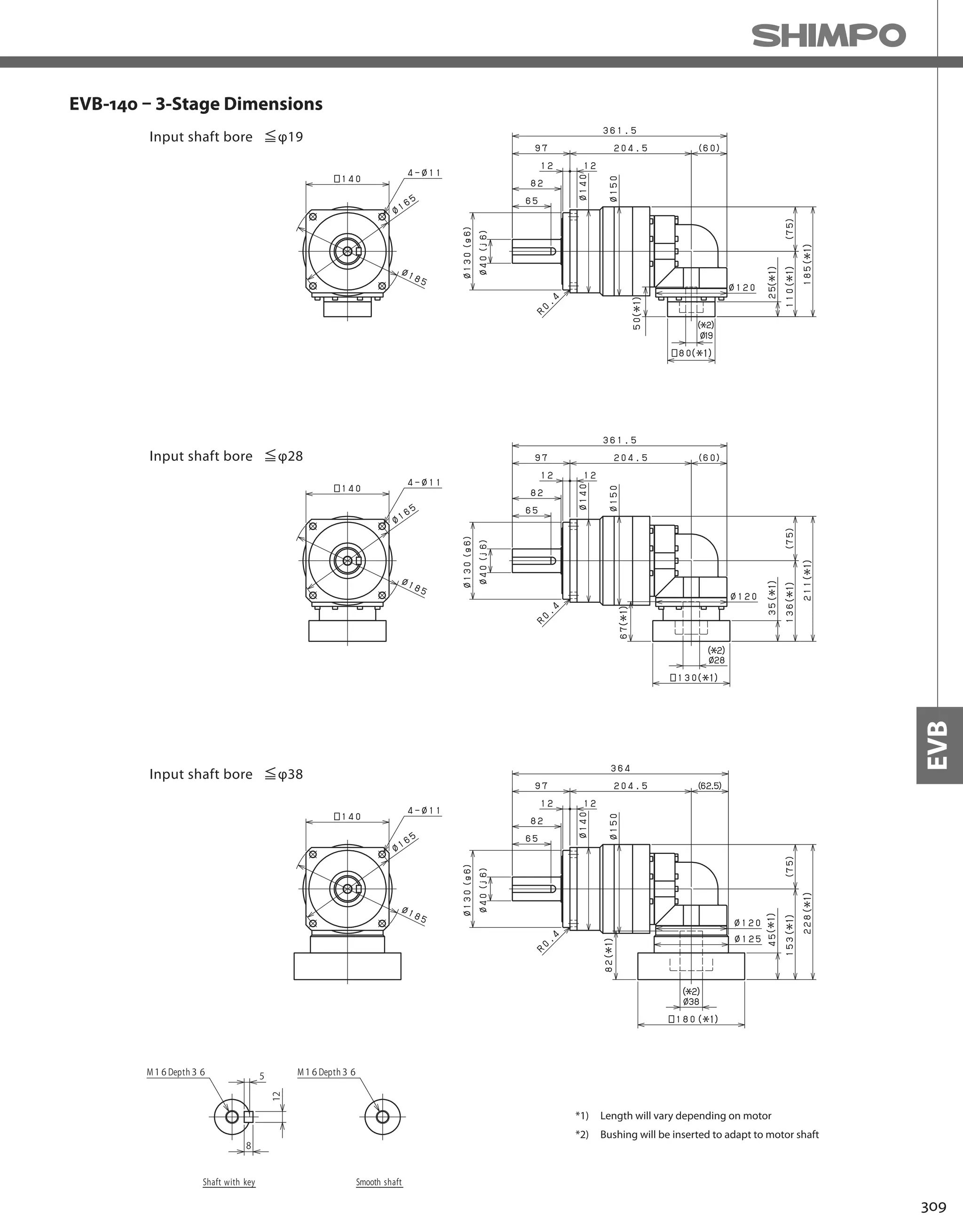

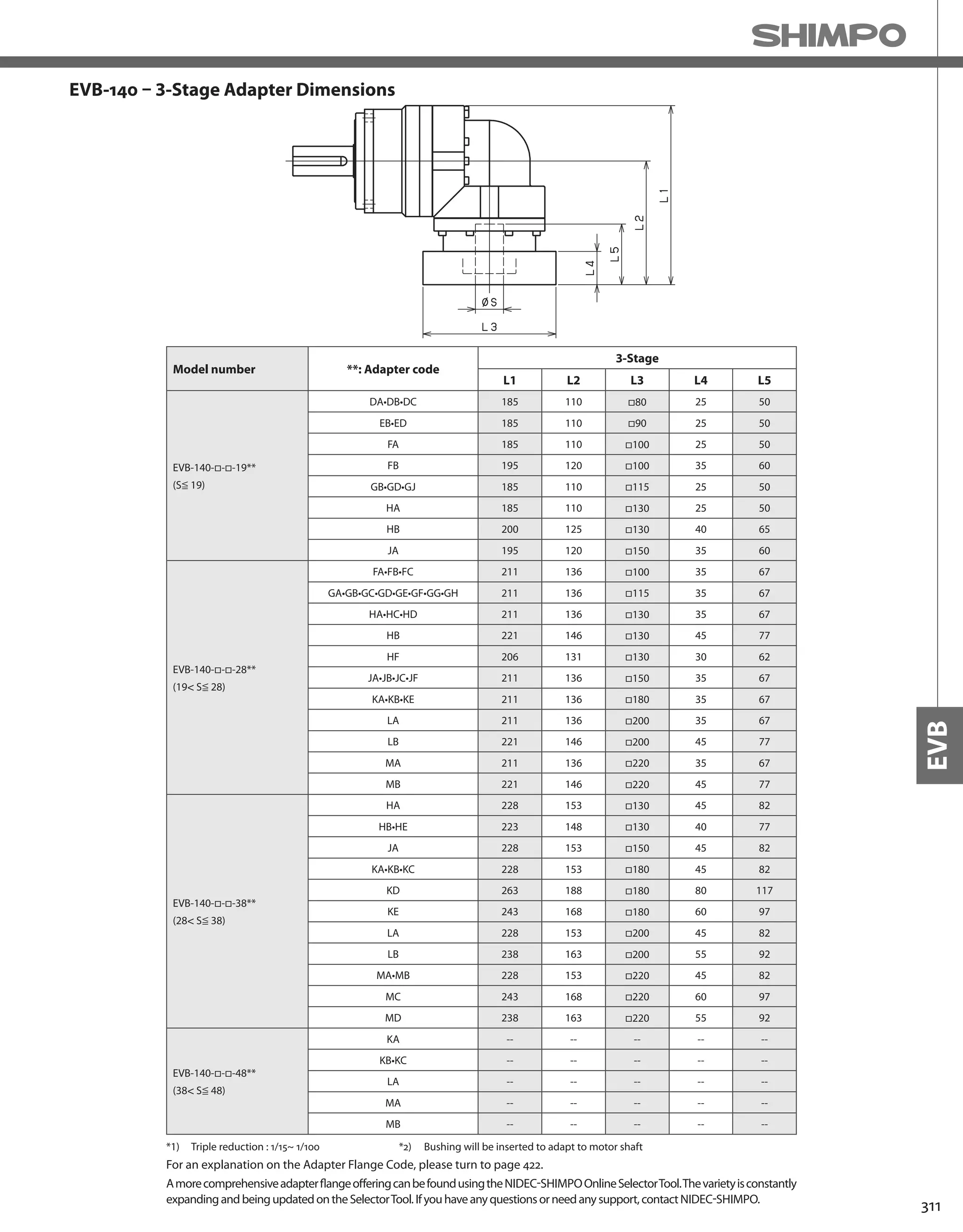
![312
EVB-SERIES Right-angle shaft
EVB-180 – 2-Stage Specifications
EVB-180 – 3-Stage Specifications
Frame Size 180
Stage 2-Stage
Ratio Units Note 3 4 5 6 7 8 9 10
Nominal Output Torque [Nm] *1 400 575 600 600 600 600 400 400
Maximum Acceleration Torque [Nm] *2 575 770 960 1120 1120 1120 775 775
Emergency Stop Torque [Nm] *3 1300 1700 2000 2500 2500 2500 2000 2000
Nominal Input Speed [rpm] *4 1500
Maximum Input Speed [rpm] *5 3000
No Load Running Torque [Nm] *6 10.8
Permitted Radial Load [N] *7 5600 6200 6700 7100 7400 7800 8100 8400
Permitted Axial Load [N] *8 4300 4900 5400 5800 6300 6600 7000 7300
Maximum Radial Load [N] *9 15000
Maximum Axial Load [N] *10 14000
Moment of Inertia (≤Ø 28) [kgcm2] -- -- -- -- -- -- -- -- --
Moment of Inertia (≤Ø 38) [kgcm2] -- 93.71 77.72 71.89 68.74 66.43 65.27 64.60 64.28
Moment of Inertia (≤ Ø 48) [kgcm2] -- 128.6 112.6 106.8 103.6 101.3 100.1 99.46 99.14
Moment of Inertia (≤ Ø 65) [kgcm2] -- 214.2 198.2 192.4 189.2 186.9 185.7 185.1 184.7
Efficiency [%] *11 93
Torsional Rigidity [Nm/arcmin] *12 175
Maximum Torsional Backlash [Arc-min] -- ≤ 6
Noise Level [dB] *13 ≤ 85
Protection Class -- *14 IP54 (IP65)
Ambient Temperature [°C] -- 0-40
Permitted Housing Temperature [°C] -- 90
Weight [kg] *15 49
Frame Size 180
Stage 3-Stage
Ratio Units Note 15 16 20 25 28 30 35 40
Nominal Output Torque [Nm] *1 400 555 600 600 600 400 600 600
Maximum Acceleration Torque [Nm] *2 775 1120 1120 1120 1120 775 1120 1120
Emergency Stop Torque [Nm] *3 2000 2500 2500 2500 2500 2000 2500 2500
Nominal Input Speed [rpm] *4 1500
Maximum Input Speed [rpm] *5 3000
No Load Running Torque [Nm] *6 4.7
Permitted Radial Load [N] *7 9600 9800 11000 11000 12000 12000 13000 13000
Permitted Axial Load [N] *8 8700 8900 9900 11000 11000 12000 13000 13000
Maximum Radial Load [N] *9 15000
Maximum Axial Load [N] *10 14000
Moment of Inertia (≤Ø 28) [kgcm2] -- 11.49 12.09 11.15 10.98 11.59 10.33 10.83 10.24
Moment of Inertia (≤Ø 38) [kgcm2] -- 20.28 20.88 19.94 19.77 20.38 19.11 19.62 19.03
Moment of Inertia (≤ Ø 48) [kgcm2] -- 25.10 25.70 24.76 24.59 25.20 23.94 24.44 23.85
Moment of Inertia (≤ Ø 65) [kgcm2] -- -- -- -- -- -- -- -- --
Efficiency [%] *11 88
Torsional Rigidity [Nm/arcmin] *12 175
Maximum Torsional Backlash [Arc-min] -- ≤ 9
Noise Level [dB] *13 ≤ 85
Protection Class -- *14 IP54 (IP65)
Ambient Temperature [°C] -- 0-40
Permitted Housing Temperature [°C] -- 90
Weight [kg] *15 36](https://image.slidesharecdn.com/shimpohighprecisioncatalog-140807090507-phpapp01/75/Shimpo-high-precision-catalog-314-2048.jpg)
![313
EVB
EVB-180 – 3-Stage Specifications
Frame Size 180
Stage 3-Stage
Ratio Units Note 45 50 60 70 80 90 100
Nominal Output Torque [Nm] *1 400 600 600 600 600 400 400
Maximum Acceleration Torque [Nm] *2 775 1120 1120 1120 1120 775 775
Emergency Stop Torque [Nm] *3 2000 2500 2500 2500 2500 2000 2000
Nominal Input Speed [rpm] *4 1500
Maximum Input Speed [rpm] *5 3000
No Load Running Torque [Nm] *6 4.7
Permitted Radial Load [N] *7 14000 14000 15000 15000 15000 15000 15000
Permitted Axial Load [N] *8 14000 14000 14000 14000 14000 14000 14000
Maximum Radial Load [N] *9 15000
Maximum Axial Load [N] *10 14000
Moment of Inertia (≤Ø 28) [kgcm2] -- 10.76 10.20 10.18 10.16 10.15 10.15 10.14
Moment of Inertia (≤Ø 38) [kgcm2] -- 19.55 18.99 18.96 18.95 18.94 18.93 18.93
Moment of Inertia (≤ Ø 48) [kgcm2] -- 24.37 23.81 23.78 23.77 23.76 23.75 23.75
Moment of Inertia (≤ Ø 65) [kgcm2] -- -- -- -- -- -- -- --
Efficiency [%] *11 88
Torsional Rigidity [Nm/arcmin] *12 175
Maximum Torsional Backlash [Arc-min] -- ≤ 9
Noise Level [dB] *13 ≤ 85
Protection Class -- *14 IP54 (IP65)
Ambient Temperature [°C] -- 0-40
Permitted Housing Temperature [°C] -- 90
Weight [kg] *15 36
*1) At nominal input speed, service life is 20,000 hours
*2) The maximum torque when starting or stopping operation
*3) The maximum torque allowed under a stress situation (Permitted 1,000 times during service life)
*4) The average input speed
*5) The maximum intermittent input speed
*6) This is the torque at no load applied on the input shaft. The input speed is 1500 rpm for EVB180
*7) At this load and nominal input speed, service life will be 20,000 hours. (The radial load applied to the output side bearing)
*8) At this load and nominal input speed, service life will be 20,000 hours. (The axial load applied to the output shaft center)
*9) The maximum radial load that the reducer can accept
*10) The maximum axial load that the reducer can accept
*11) The efficiency at the nominal torque rating
*12) This does not include the lost motion
*13) Contact NIDEC-SHIMPO for the testing conditions and environment
*14) IP65 (wash-down) is available as an option. Contact NIDEC-SHIMPO for more details and our food grade options
*15) The weight may vary slightly between models](https://image.slidesharecdn.com/shimpohighprecisioncatalog-140807090507-phpapp01/75/Shimpo-high-precision-catalog-315-2048.jpg)


![318
EVB-SERIES Right-angle shaft
EVB-220 – 2-Stage Specifications
EVB-220 – 3-Stage Specifications
Frame Size 220
Stage 2-Stage
Ratio Units Note 3 4 5 6 7 8 9 10
Nominal Output Torque [Nm] *1 575 765 960 1150 1200 1200 800 800
Maximum Acceleration Torque [Nm] *2 1015 1355 1695 1840 1840 1760 1520 1280
Emergency Stop Torque [Nm] *3 2500 3300 4000 4500 4500 4500 3600 3600
Nominal Input Speed [rpm] *4 1000
Maximum Input Speed [rpm] *5 2000
No Load Running Torque [Nm] *6 14.5
Permitted Radial Load [N] *7 5800 6400 6900 7300 7700 8000 8400 8700
Permitted Axial Load [N] *8 6400 7200 7900 8600 9200 9700 10000 11000
Maximum Radial Load [N] *9 15000
Maximum Axial Load [N] *10 14000
Moment of Inertia (≤Ø 38) [kgcm2] -- -- -- -- -- -- -- -- --
Moment of Inertia (≤Ø 48) [kgcm2] -- 148.0 122.9 113.3 108.1 104.7 102.7 101.6 101.0
Moment of Inertia (≤ Ø 65) [kgcm2] -- 223.2 198.1 188.6 183.3 180.0 178.0 176.8 176.2
Efficiency [%] *11 93
Torsional Rigidity [Nm/arcmin] *12 400
Maximum Torsional Backlash [Arc-min] -- ≤ 6
Noise Level [dB] *13 ≤ 85
Protection Class -- *14 IP54 (IP65)
Ambient Temperature [°C] -- 0-40
Permitted Housing Temperature [°C] -- 90
Weight [kg] *15 66
Frame Size 220
Stage 3-Stage
Ratio Units Note 15 16 20 25 28 30 35 40
Nominal Output Torque [Nm] *1 800 1200 1200 1200 1200 800 1200 1200
Maximum Acceleration Torque [Nm] *2 1280 1840 1840 1840 1840 1280 1840 1840
Emergency Stop Torque [Nm] *3 3600 4500 4500 4500 4500 3600 4500 4500
Nominal Input Speed [rpm] *4 1000
Maximum Input Speed [rpm] *5 2000
No Load Running Torque [Nm] *6 10.2
Permitted Radial Load [N] *7 9900 10000 11000 12000 12000 13000 13000 14000
Permitted Axial Load [N] *8 13000 13000 14000 14000 14000 14000 14000 14000
Maximum Radial Load [N] *9 15000
Maximum Axial Load [N] *10 14000
Moment of Inertia (≤Ø 38) [kgcm2] -- 36.32 37.24 35.75 35.47 36.39 34.39 35.21 34.25
Moment of Inertia (≤Ø 48) [kgcm2] -- 66.14 67.06 65.57 65.28 66.21 64.21 65.03 64.07
Moment of Inertia (≤ Ø 65) [kgcm2] -- -- -- -- -- -- -- -- --
Efficiency [%] *11 88
Torsional Rigidity [Nm/arcmin] *12 400
Maximum Torsional Backlash [Arc-min] -- ≤ 9
Noise Level [dB] *13 ≤ 85
Protection Class -- *14 IP54 (IP65)
Ambient Temperature [°C] -- 0-40
Permitted Housing Temperature [°C] -- 90
Weight [kg] *15 67](https://image.slidesharecdn.com/shimpohighprecisioncatalog-140807090507-phpapp01/75/Shimpo-high-precision-catalog-320-2048.jpg)
![319
EVB
EVB-220 – 3-Stage Specifications
Frame Size 220
Stage 3-Stage
Ratio Units Note 45 50 60 70 80 90 100
Nominal Output Torque [Nm] *1 800 1200 1200 1200 1200 800 800
Maximum Acceleration Torque [Nm] *2 1040 1840 1840 1840 1440 1040 960
Emergency Stop Torque [Nm] *3 3600 4500 4500 4500 4500 3600 3600
Nominal Input Speed [rpm] *4 1000
Maximum Input Speed [rpm] *5 2000
No Load Running Torque [Nm] *6 10.2
Permitted Radial Load [N] *7 14000 15000 15000 15000 15000 15000 15000
Permitted Axial Load [N] *8 14000 14000 14000 14000 14000 14000 14000
Maximum Radial Load [N] *9 15000
Maximum Axial Load [N] *10 14000
Moment of Inertia (≤Ø 38) [kgcm2] -- 35.10 34.18 34.14 34.11 34.10 34.09 34.08
Moment of Inertia (≤Ø 48) [kgcm2] -- 64.92 63.99 63.95 63.93 63.91 63.90 63.90
Moment of Inertia (≤ Ø 65) [kgcm2] -- -- -- -- -- -- -- --
Efficiency [%] *11 88
Torsional Rigidity [Nm/arcmin] *12 400
Maximum Torsional Backlash [Arc-min] -- ≤ 9
Noise Level [dB] *13 ≤ 85
Protection Class -- *14 IP54 (IP65)
Ambient Temperature [°C] -- 0-40
Permitted Housing Temperature [°C] -- 90
Weight [kg] *15 67
*1) At nominal input speed, service life is 20,000 hours
*2) The maximum torque when starting or stopping operation
*3) The maximum torque allowed under a stress situation (Permitted 1,000 times during service life)
*4) The average input speed
*5) The maximum intermittent input speed
*6) This is the torque at no load applied on the input shaft. The input speed is 1000 rpm for EVB220
*7) At this load and nominal input speed, service life will be 20,000 hours. (The radial load applied to the output side bearing)
*8) At this load and nominal input speed, service life will be 20,000 hours. (The axial load applied to the output shaft center)
*9) The maximum radial load that the reducer can accept
*10) The maximum axial load that the reducer can accept
*11) The efficiency at the nominal torque rating
*12) This does not include the lost motion
*13) Contact NIDEC-SHIMPO for the testing conditions and environment
*14) IP65 (wash-down) is available as an option. Contact NIDEC-SHIMPO for more details and our food grade options
*15) The weight may vary slightly between models](https://image.slidesharecdn.com/shimpohighprecisioncatalog-140807090507-phpapp01/75/Shimpo-high-precision-catalog-321-2048.jpg)


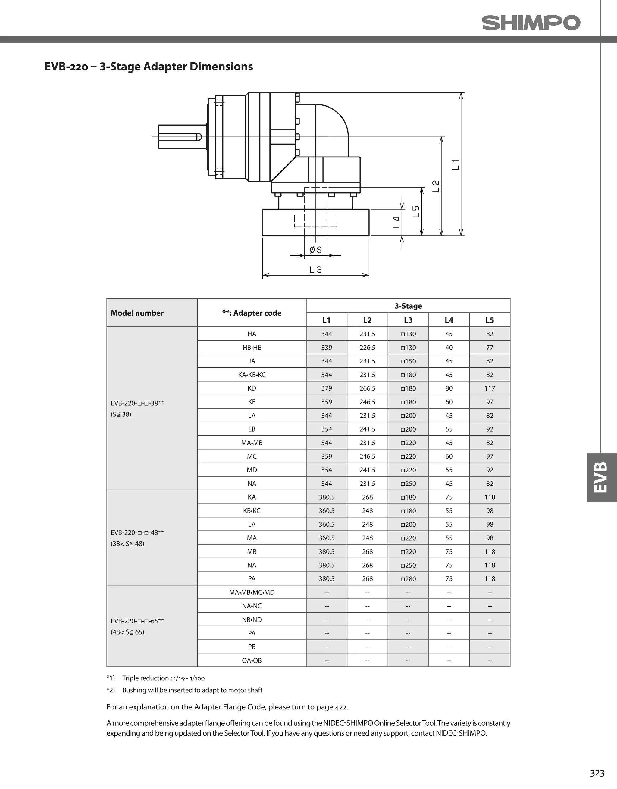
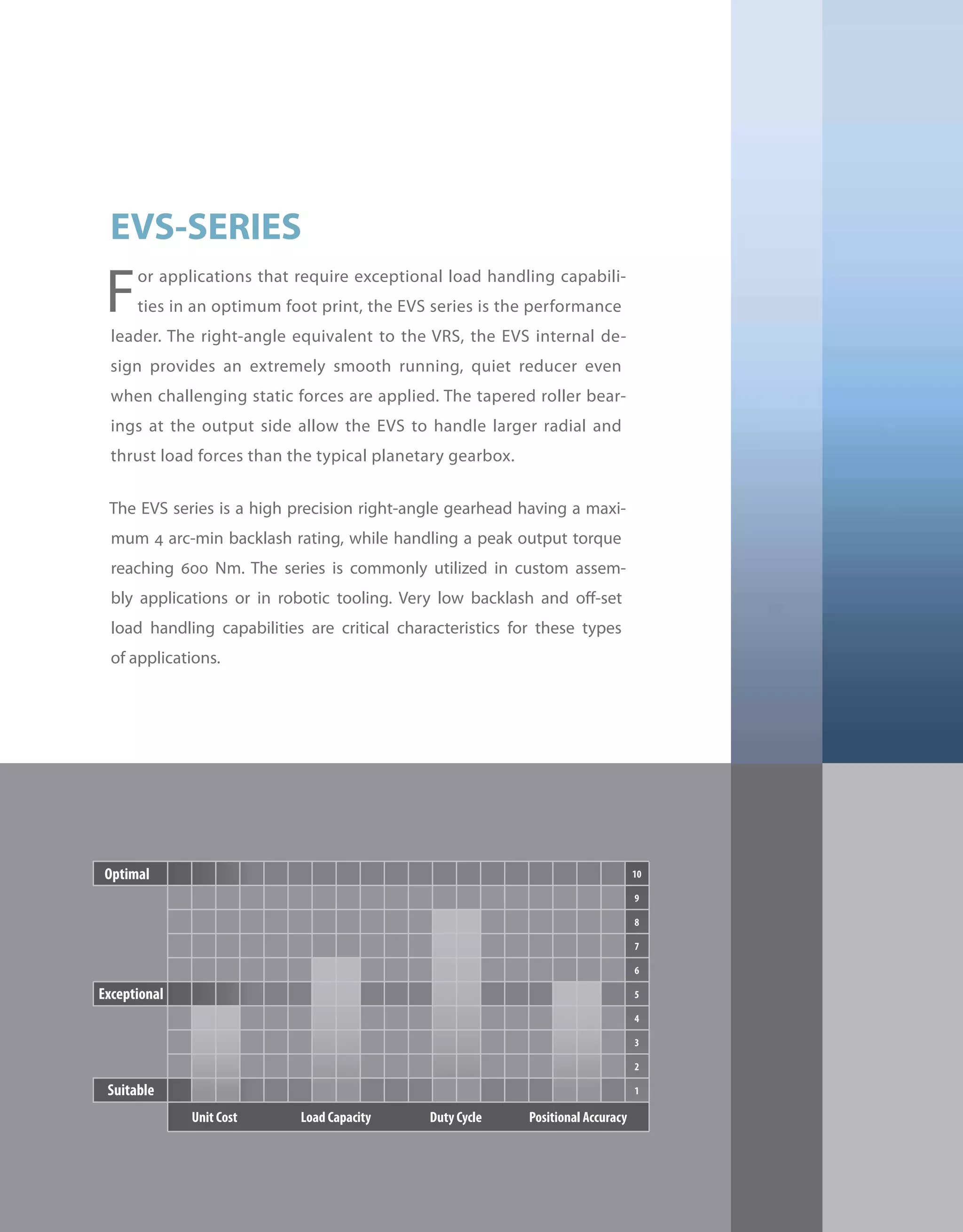
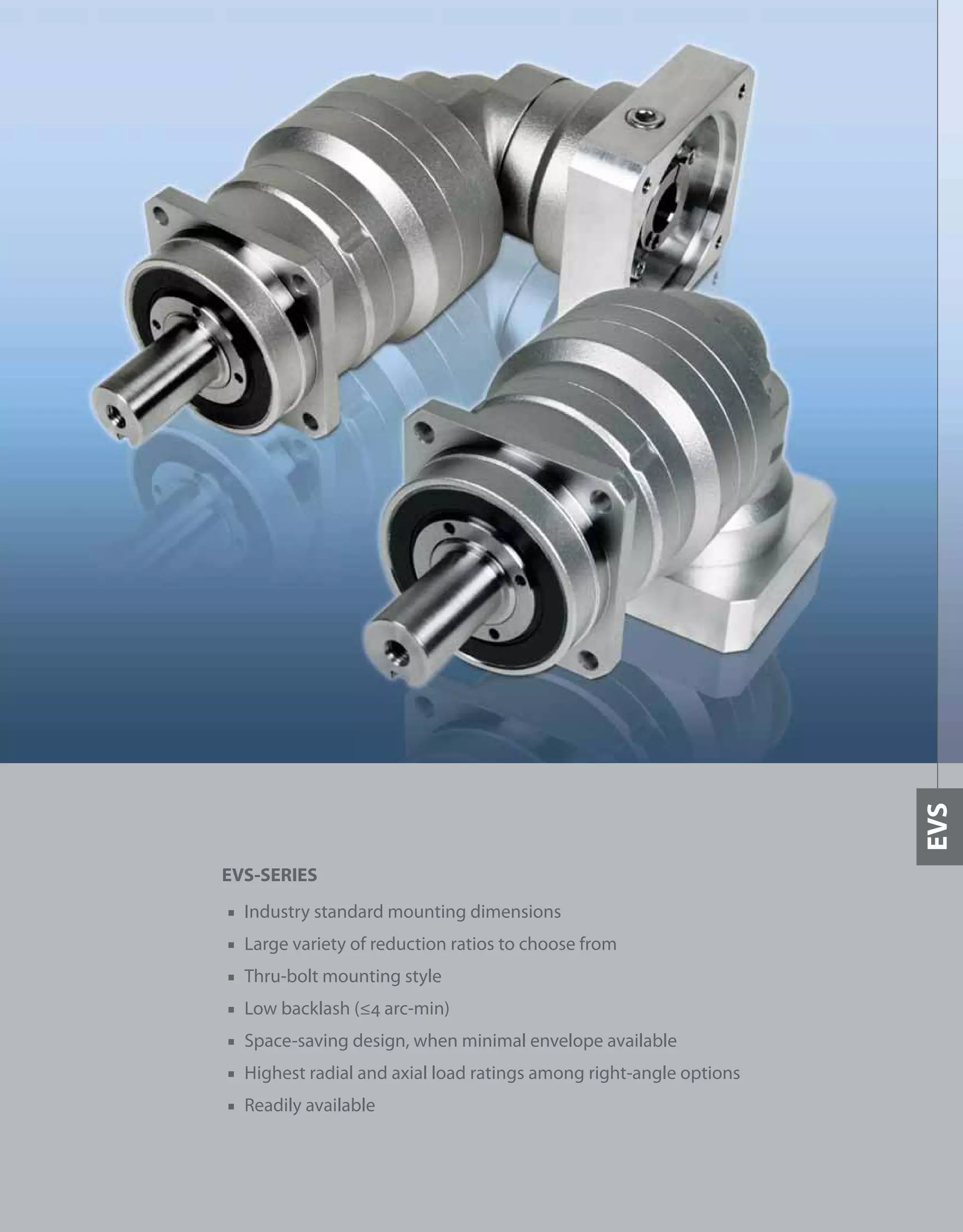
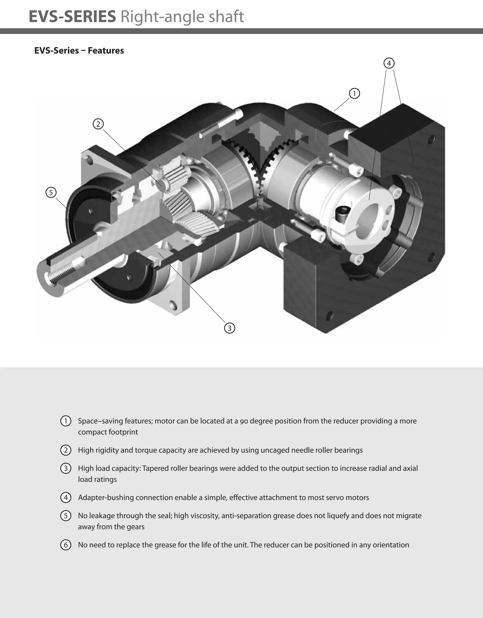

![328
EVS-SERIES Right-angle shaft
EVS-060 – 2-Stage Specifications
EVS-060 – 3-Stage Specifications
Frame Size 060
Stage 2-Stage
Ratio Unit Note 3 4 5 6 7 8 9 10
Nominal Output Torque [Nm] *1 12 16 22 24 24 24 16 16
Maximum Acceleration Torque [Nm] *2 24 32 40 45 45 45 32 32
Emergency Stop Torque [Nm] *3 50 65 80 90 90 90 65 65
Nominal Input Speed [rpm] *4 3000
Maximum Input Speed [rpm] *5 6000
No Load Running Torque [Nm] *6 0.33
Permitted Radial Load [N] *7 1700 1900 2000 2100 2200 2300 2400 2400
Permitted Axial Load [N] *8 2300 2500 2700 2700 2700 2700 2700 2700
Maximum Radial Load [N] *9 3000
Maximum Axial Load [N] *10 2700
Moment of Inertia (≤ Ø 8) [kgcm2] -- 0.320 0.271 0.251 0.242 0.235 0.232 0.229 0.228
Moment of Inertia (≤ Ø 14) [kgcm2] -- 0.395 0.346 0.326 0.317 0.310 0.307 0.304 0.303
Moment of Inertia (≤ Ø 19) [kgcm2] -- 0.584 0.535 0.516 0.506 0.500 0.496 0.494 0.492
Efficiency [%] *11 93
Torsional Rigidity [Nm/arc-min] *12 3
Maximum Torsional Backlash [arc-min] -- ≤ 4
Noise Level [dB] *13 80
Protection Class -- *14 IP54 (IP65)
Ambient Temperature [°C] -- 0-40
Permitted Housing Temperature [°C] -- 90
Weight [kg] *15 2
Frame Size 060
Stage 3-Stage
Ratio Unit Note 15 16 20 25 28 30 35 40
Nominal Output Torque [Nm] *1 16 24 24 24 24 16 24 24
Maximum Acceleration Torque [Nm] *2 32 45 45 45 45 32 45 45
Emergency Stop Torque [Nm] *3 65 90 90 90 90 65 90 90
Nominal Input Speed [rpm] *4 3000
Maximum Input Speed [rpm] *5 6000
No Load Running Torque [Nm] *6 0.20
Permitted Radial Load [N] *7 2800 2800 3000 3000 3000 3000 3000 3000
Permitted Axial Load [N] *8 2700 2700 2700 2700 2700 2700 2700 2700
Maximum Radial Load [N] *9 3000
Maximum Axial Load [N] *10 2700
Moment of Inertia (≤ Ø 8) [kgcm2] -- 0.074 0.079 0.072 0.071 0.077 0.062 0.070 0.061
Moment of Inertia (≤ Ø 14) [kgcm2] -- 0.118 0.124 0.116 0.115 0.122 0.106 0.115 0.106
Moment of Inertia (≤ Ø 19) [kgcm2] -- -- -- -- -- -- -- -- --
Efficiency [%] *11 88
Torsional Rigidity [Nm/arc-min] *12 3
Maximum Torsional Backlash [arc-min] -- ≤ 7
Noise Level [dB] *13 80
Protection Class -- *14 IP54 (IP65)
Ambient Temperature [°C] -- 0-40
Permitted Housing Temperature [°C] -- 90
Weight [kg] *15 1.8](https://image.slidesharecdn.com/shimpohighprecisioncatalog-140807090507-phpapp01/75/Shimpo-high-precision-catalog-330-2048.jpg)
![329
EVS
EVS-060 – 3-Stage Specifications
Frame Size 060
Stage 3-Stage
Ratio Unit Note 45 50 60 70 80 90 100
Nominal Output Torque [Nm] *1 16 24 24 24 24 16 16
Maximum Acceleration Torque [Nm] *2 32 45 45 45 45 32 32
Emergency Stop Torque [Nm] *3 65 90 90 90 90 65 65
Nominal Input Speed [rpm] *4 3000
Maximum Input Speed [rpm] *5 6000
No Load Running Torque [Nm] *6 0.20
Permitted Radial Load [N] *7 3000 3000 3000 3000 3000 3000 3000
Permitted Axial Load [N] *8 2700 2700 2700 2700 2700 2700 2700
Maximum Radial Load [N] *9 3000
Maximum Axial Load [N] *10 2700
Moment of Inertia (≤ Ø 8) [kgcm2] -- 0.070 0.061 0.061 0.061 0.061 0.061 0.061
Moment of Inertia (≤ Ø 14) [kgcm2] -- 0.115 0.106 0.106 0.106 0.105 0.105 0.105
Moment of Inertia (≤ Ø 19) [kgcm2] -- -- -- -- -- -- -- --
Efficiency [%] *11 88
Torsional Rigidity [Nm/arc-min] *12 3
Maximum Torsional Backlash [arc-min] -- ≤ 7
Noise Level [dB] *13 80
Protection Class -- *14 IP54 (IP65)
Ambient Temperature [°C] -- 0-40
Permitted Housing Temperature [°C] -- 90
Weight [kg] *15 1.8
*1) At nominal input speed, service life is 20,000 hours
*2) The maximum torque when starting or stopping operation
*3) The maximum torque allowed under a stress situation (Permitted 1,000 times during service life)
*4) The average input speed
*5) The maximum intermittent input speed
*6) This is the torque at no load applied on the input shaft. The input speed is 3000 rpm for EVS060
*7) At this load and nominal input speed, service life will be 20,000 hours. (The radial load applied to the output side bearing)
*8) At this load and nominal input speed, service life will be 20,000 hours. (The axial load applied to the output shaft center)
*9) The maximum radial load that the reducer can accept
*10) The maximum axial load that the reducer can accept
*11) The efficiency at the nominal torque rating
*12) This does not include the lost motion
*13) Contact NIDEC-SHIMPO for the testing conditions and environment
*14) IP65 (wash-down) is available as an option. Contact NIDEC-SHIMPO for more details and our food grade options
*15) The weight may vary slightly between models](https://image.slidesharecdn.com/shimpohighprecisioncatalog-140807090507-phpapp01/75/Shimpo-high-precision-catalog-331-2048.jpg)


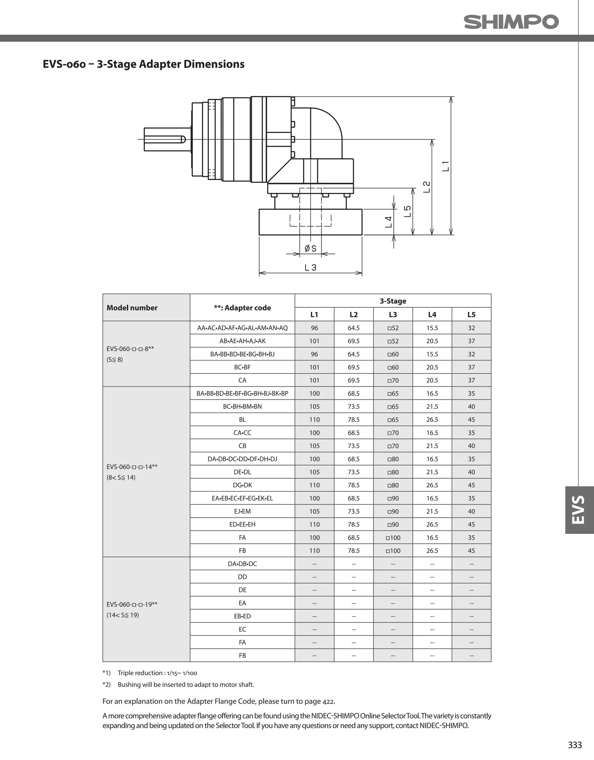
![334
EVS-SERIES Right-angle shaft
EVS-075 – 2-Stage Specifications
EVS-075 – 3-Stage Specifications
Frame Size 075
Stage 2-Stage
Ratio Unit Note 3 4 5 6 7 8 9 10
Nominal Output Torque [Nm] *1 45 60 65 65 65 65 45 45
Maximum Acceleration Torque [Nm] *2 65 90 90 90 90 90 65 65
Emergency Stop Torque [Nm] *3 130 170 220 220 220 220 170 170
Nominal Input Speed [rpm] *4 3000
Maximum Input Speed [rpm] *5 6000
No Load Running Torque [Nm] *6 1.13
Permitted Radial Load [N] *7 2300 2500 2700 2800 3000 3100 3200 3300
Permitted Axial Load [N] *8 3400 3700 3900 3900 3900 3900 3900 3900
Maximum Radial Load [N] *9 4300
Maximum Axial Load [N] *10 3900
Moment of Inertia (≤ Ø 8) [kgcm2] -- -- -- -- -- -- -- -- --
Moment of Inertia (≤ Ø 14) [kgcm2] -- 2.070 1.870 1.780 1.740 1.720 1.700 1.690 1.690
Moment of Inertia (≤ Ø 19) [kgcm2] -- 2.400 2.200 2.110 2.070 2.050 2.030 2.020 2.020
Moment of Inertia (≤ Ø 28) [kgcm2] -- 4.530 4.320 4.240 4.200 4.170 4.160 4.150 4.150
Efficiency [%] *11 93
Torsional Rigidity [Nm/arc-min] *12 10
Maximum Torsional Backlash [arc-min] -- ≤ 4
Noise Level [dB] *13 80
Protection Class -- *14 IP54 (IP65)
Ambient Temperature [°C] -- 0-40
Permitted Housing Temperature [°C] -- 90
Weight [kg] *15 4.8
Frame Size 075
Stage 3-Stage
Ratio Unit Note 15 16 20 25 28 30 35 40
Nominal Output Torque [Nm] *1 45 65 65 65 65 45 65 65
Maximum Acceleration Torque [Nm] *2 65 110 110 110 110 65 110 110
Emergency Stop Torque [Nm] *3 170 220 220 220 220 170 220 220
Nominal Input Speed [rpm] *4 3000
Maximum Input Speed [rpm] *5 6000
No Load Running Torque [Nm] *6 0.55
Permitted Radial Load [N] *7 3700 3800 4000 4300 4300 4300 4300 4300
Permitted Axial Load [N] *8 3900 3900 3900 3900 3900 3900 3900 3900
Maximum Radial Load [N] *9 4300
Maximum Axial Load [N] *10 3900
Moment of Inertia (≤ Ø 8) [kgcm2] -- 0.330 0.380 0.330 0.320 0.370 0.250 0.320 0.250
Moment of Inertia (≤ Ø 14) [kgcm2] -- 0.410 0.460 0.400 0.400 0.450 0.320 0.400 0.320
Moment of Inertia (≤ Ø 19) [kgcm2] -- 0.600 0.650 0.590 0.590 0.640 0.510 0.580 0.510
Moment of Inertia (≤ Ø 28) [kgcm2] -- -- -- -- -- -- -- -- --
Efficiency [%] *11 88
Torsional Rigidity [Nm/arc-min] *12 10
Maximum Torsional Backlash [arc-min] -- ≤ 7
Noise Level [dB] *13 80
Protection Class -- *14 IP54 (IP65)
Ambient Temperature [°C] -- 0-40
Permitted Housing Temperature [°C] -- 90
Weight [kg] *15 4.1](https://image.slidesharecdn.com/shimpohighprecisioncatalog-140807090507-phpapp01/75/Shimpo-high-precision-catalog-336-2048.jpg)
![335
EVS
EVS-075 – 3-Stage Specifications
Frame Size 075
Stage 3-Stage
Ratio Unit Note 45 50 60 70 80 90 100
Nominal Output Torque [Nm] *1 45 65 65 65 65 45 45
Maximum Acceleration Torque [Nm] *2 65 110 110 110 110 65 65
Emergency Stop Torque [Nm] *3 170 220 220 220 220 170 170
Nominal Input Speed [rpm] *4 3000
Maximum Input Speed [rpm] *5 6000
No Load Running Torque [Nm] *6 0.55
Permitted Radial Load [N] *7 4300 4300 4300 4300 4300 4300 4300
Permitted Axial Load [N] *8 3900 3900 3900 3900 3900 3900 3900
Maximum Radial Load [N] *9 4300
Maximum Axial Load [N] *10 3900
Moment of Inertia (≤ Ø 8) [kgcm2] -- 0.320 0.250 0.250 0.250 0.250 0.250 0.250
Moment of Inertia (≤ Ø 14) [kgcm2] -- 0.390 0.320 0.320 0.320 0.320 0.320 0.320
Moment of Inertia (≤ Ø 19) [kgcm2] -- 0.580 0.510 0.510 0.510 0.510 0.510 0.510
Moment of Inertia (≤ Ø 28) [kgcm2] -- -- -- -- -- -- -- --
Efficiency [%] *11 88
Torsional Rigidity [Nm/arc-min] *12 10
Maximum Torsional Backlash [arc-min] -- ≤ 7
Noise Level [dB] *13 80
Protection Class -- *14 IP54 (IP65)
Ambient Temperature [°C] -- 0-40
Permitted Housing Temperature [°C] -- 90
Weight [kg] *15 4.1
*1) At nominal input speed, service life is 20,000 hours
*2) The maximum torque when starting or stopping operation
*3) The maximum torque allowed under a stress situation (Permitted 1,000 times during service life)
*4) The average input speed
*5) The maximum intermittent input speed
*6) This is the torque at no load applied on the input shaft. The input speed is 3000 rpm for EVS075
*7) At this load and nominal input speed, service life will be 20,000 hours. (The radial load applied to the output side bearing)
*8) At this load and nominal input speed, service life will be 20,000 hours. (The axial load applied to the output shaft center)
*9) The maximum radial load that the reducer can accept
*10) The maximum axial load that the reducer can accept
*11) The efficiency at the nominal torque rating
*12) This does not include the lost motion
*13) Contact NIDEC-SHIMPO for the testing conditions and environment
*14) IP65 (wash-down) is available as an option. Contact NIDEC-SHIMPO for more details and our food grade options
*15) The weight may vary slightly between models](https://image.slidesharecdn.com/shimpohighprecisioncatalog-140807090507-phpapp01/75/Shimpo-high-precision-catalog-337-2048.jpg)


![340
EVS-SERIES Right-angle shaft
EVS-100 – 2-Stage Specifications
EVS-100 – 3-Stage Specifications
Frame Size 100
Stage 2-Stage
Ratio Unit Note 3 4 5 6 7 8 9 10
Nominal Output Torque [Nm] *1 75 100 120 150 150 150 110 110
Maximum Acceleration Torque [Nm] *2 150 200 240 300 300 300 200 200
Emergency Stop Torque [Nm] *3 320 430 500 550 550 550 450 450
Nominal Input Speed [rpm] *4 3000
Maximum Input Speed [rpm] *5 6000
No Load Running Torque [Nm] *6 1.88
Permitted Radial Load [N] *7 3400 3700 4000 4200 4400 4600 4800 4900
Permitted Axial Load [N] *8 4800 5200 5600 5900 6100 6300 6300 6300
Maximum Radial Load [N] *9 7000
Maximum Axial Load [N] *10 6300
Moment of Inertia (≤ Ø 14) [kgcm2] -- -- -- -- -- -- -- -- --
Moment of Inertia (≤ Ø 19) [kgcm2] -- 6.610 5.410 4.970 4.730 4.620 4.530 4.470 4.450
Moment of Inertia (≤ Ø 28) [kgcm2] -- 8.210 7.010 6.570 6.330 6.220 6.120 6.070 6.040
Moment of Inertia (≤ Ø 38) [kgcm2] -- 15.280 14.080 13.640 13.400 13.290 13.200 13.140 13.110
Efficiency [%] *11 93
Torsional Rigidity [Nm/arc-min] *12 31
Maximum Torsional Backlash [arc-min] -- ≤ 4
Noise Level [dB] *13 85
Protection Class -- *14 IP54 (IP65)
Ambient Temperature [°C] -- 0-40
Permitted Housing Temperature [°C] -- 90
Weight [kg] *15 10.5
Frame Size 100
Stage 3-Stage
Ratio Unit Note 15 16 20 25 28 30 35 40
Nominal Output Torque [Nm] *1 110 130 150 150 150 110 150 150
Maximum Acceleration Torque [Nm] *2 200 260 300 300 300 200 300 300
Emergency Stop Torque [Nm] *3 450 550 550 550 550 450 550 550
Nominal Input Speed [rpm] *4 3000
Maximum Input Speed [rpm] *5 6000
No Load Running Torque [Nm] *6 1.11
Permitted Radial Load [N] *7 5600 5700 6100 6500 6700 6900 7000 7000
Permitted Axial Load [N] *8 6300 6300 6300 6300 6300 6300 6300 6300
Maximum Radial Load [N] *9 7000
Maximum Axial Load [N] *10 6300
Moment of Inertia (≤ Ø 14) [kgcm2] -- 2.240 2.450 2.190 2.180 2.400 1.870 2.160 1.860
Moment of Inertia (≤ Ø 19) [kgcm2] -- 2.570 2.780 2.520 2.510 2.730 2.200 2.490 2.190
Moment of Inertia (≤ Ø 28) [kgcm2] -- 4.700 4.910 4.650 4.630 4.860 4.330 4.620 4.320
Moment of Inertia (≤ Ø 38) [kgcm2] -- -- -- -- -- -- -- -- --
Efficiency [%] *11 88
Torsional Rigidity [Nm/arc-min] *12 31
Maximum Torsional Backlash [arc-min] -- ≤ 7
Noise Level [dB] *13 85
Protection Class -- *14 IP54 (IP65)
Ambient Temperature [°C] -- 0-40
Permitted Housing Temperature [°C] -- 90
Weight [kg] *15 10.1](https://image.slidesharecdn.com/shimpohighprecisioncatalog-140807090507-phpapp01/75/Shimpo-high-precision-catalog-342-2048.jpg)
![341
EVS
EVS-100 – 3-Stage Specifications
Frame Size 100
Stage 3-Stage
Ratio Unit Note 45 50 60 70 80 90 100
Nominal Output Torque [Nm] *1 110 150 150 150 150 110 110
Maximum Acceleration Torque [Nm] *2 200 300 300 300 300 200 200
Emergency Stop Torque [Nm] *3 450 550 550 550 550 450 450
Nominal Input Speed [rpm] *4 3000
Maximum Input Speed [rpm] *5 6000
No Load Running Torque [Nm] *6 1.11
Permitted Radial Load [N] *7 7000 7000 7000 7000 7000 7000 7000
Permitted Axial Load [N] *8 6300 6300 6300 6300 6300 6300 6300
Maximum Radial Load [N] *9 7000
Maximum Axial Load [N] *10 6300
Moment of Inertia (≤ Ø 14) [kgcm2] -- 2.150 1.860 1.850 1.850 1.850 1.850 1.850
Moment of Inertia (≤ Ø 19) [kgcm2] -- 2.480 2.190 2.180 2.180 2.180 2.180 2.180
Moment of Inertia (≤ Ø 28) [kgcm2] -- 4.610 4.310 4.310 4.310 4.310 4.310 4.310
Moment of Inertia (≤ Ø 38) [kgcm2] -- -- -- -- -- -- -- --
Efficiency [%] *11 88
Torsional Rigidity [Nm/arc-min] *12 31
Maximum Torsional Backlash [arc-min] -- ≤ 7
Noise Level [dB] *13 85
Protection Class -- *14 IP54 (IP65)
Ambient Temperature [°C] -- 0-40
Permitted Housing Temperature [°C] -- 90
Weight [kg] *15 10.1
*1) At nominal input speed, service life is 20,000 hours
*2) The maximum torque when starting or stopping operation
*3) The maximum torque allowed under a stress situation (Permitted 1,000 times during service life)
*4) The average input speed
*5) The maximum intermittent input speed
*6) This is the torque at no load applied on the input shaft. The input speed is 3000 rpm for EVS100
*7) At this load and nominal input speed, service life will be 20,000 hours. (The radial load applied to the output side bearing)
*8) At this load and nominal input speed, service life will be 20,000 hours. (The axial load applied to the output shaft center)
*9) The maximum radial load that the reducer can accept
*10) The maximum axial load that the reducer can accept
*11) The efficiency at the nominal torque rating
*12) This does not include the lost motion
*13) Contact NIDEC-SHIMPO for the testing conditions and environment
*14) IP65 (wash-down) is available as an option. Contact NIDEC-SHIMPO for more details and our food grade options
*15) The weight may vary slightly between models](https://image.slidesharecdn.com/shimpohighprecisioncatalog-140807090507-phpapp01/75/Shimpo-high-precision-catalog-343-2048.jpg)


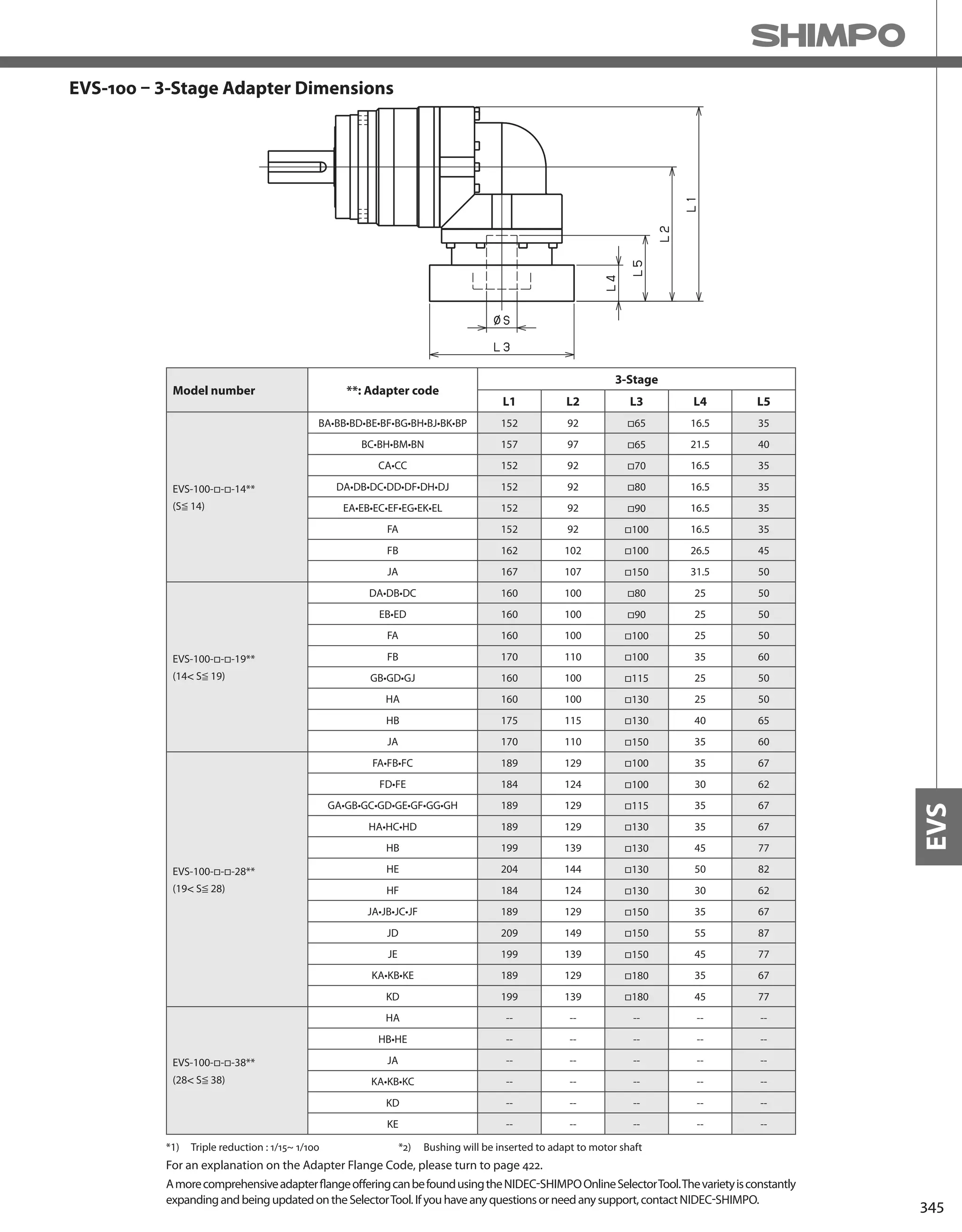
![346
EVS-SERIES Right-angle shaft
EVS-140 – 2-Stage Specifications
EVS-140 – 3-Stage Specifications
Frame Size 140
Stage 2-Stage
Ratio Unit Note 3 4 5 6 7 8 9 10
Nominal Output Torque [Nm] *1 130 170 200 260 300 300 200 200
Maximum Acceleration Torque [Nm] *2 260 340 400 520 600 600 400 400
Emergency Stop Torque [Nm] *3 700 950 1100 1100 1100 1100 750 750
Nominal Input Speed [rpm] *4 2000
Maximum Input Speed [rpm] *5 4000
No Load Running Torque [Nm] *6 3.26
Permitted Radial Load [N] *7 6700 7400 7900 8300 8700 9100 9400 9700
Permitted Axial Load [N] *8 9000 9000 9000 9000 9000 9000 9000 9000
Maximum Radial Load [N] *9 10000
Maximum Axial Load [N] *10 9000
Moment of Inertia (≤ Ø 19) [kgcm2] -- -- -- -- -- -- -- -- --
Moment of Inertia (≤ Ø 28) [kgcm2] -- 23.010 18.490 16.850 15.970 15.550 15.210 14.750 14.640
Moment of Inertia (≤ Ø 38) [kgcm2] -- 27.380 22.860 21.220 20.340 19.920 19.580 19.120 19.020
Moment of Inertia (≤ Ø 48) [kgcm2] -- 40.610 36.090 34.450 33.570 33.150 32.810 32.250 32.250
Efficiency [%] *11 93
Torsional Rigidity [Nm/arc-min] *12 60
Maximum Torsional Backlash [arc-min] -- ≤ 4
Noise Level [dB] *13 85
Protection Class -- *14 IP54 (IP65)
Ambient Temperature [°C] -- 0-40
Permitted Housing Temperature [°C] -- 90
Weight [kg] *15 20.6
Frame Size 140
Stage 3-Stage
Ratio Unit Note 15 16 20 25 28 30 35 40
Nominal Output Torque [Nm] *1 200 300 300 300 300 200 300 300
Maximum Acceleration Torque [Nm] *2 400 600 600 600 600 400 600 600
Emergency Stop Torque [Nm] *3 750 1100 1100 1100 1100 750 1100 1100
Nominal Input Speed [rpm] *4 2000
Maximum Input Speed [rpm] *5 4000
No Load Running Torque [Nm] *6 2.56
Permitted Radial Load [N] *7 10000 10000 10000 10000 10000 10000 10000 10000
Permitted Axial Load [N] *8 9000 9000 9000 9000 9000 9000 9000 9000
Maximum Radial Load [N] *9 10000
Maximum Axial Load [N] *10 9000
Moment of Inertia (≤ Ø 19) [kgcm2] -- 6.400 7.290 6.220 6.150 7.090 4.990 6.090 4.940
Moment of Inertia (≤ Ø 28) [kgcm2] -- 7.990 8.880 7.810 7.750 8.680 6.580 7.680 6.540
Moment of Inertia (≤ Ø 38) [kgcm2] -- 15.060 15.950 14.880 14.820 15.750 13.660 14.760 13.610
Moment of Inertia (≤ Ø 48) [kgcm2] -- -- -- -- -- -- -- -- --
Efficiency [%] *11 88
Torsional Rigidity [Nm/arc-min] *12 60
Maximum Torsional Backlash [arc-min] -- ≤ 7
Noise Level [dB] *13 85
Protection Class -- *14 IP54 (IP65)
Ambient Temperature [°C] -- 0-40
Permitted Housing Temperature [°C] -- 90
Weight [kg] *15 20.7](https://image.slidesharecdn.com/shimpohighprecisioncatalog-140807090507-phpapp01/75/Shimpo-high-precision-catalog-348-2048.jpg)
![347
EVS
EVS-140 – 3-Stage Specifications
Frame Size 140
Stage 3-Stage
Ratio Unit Note 45 50 60 70 80 90 100
Nominal Output Torque [Nm] *1 200 300 300 300 300 200 200
Maximum Acceleration Torque [Nm] *2 400 600 600 600 600 400 400
Emergency Stop Torque [Nm] *3 750 1100 1100 1100 1100 750 750
Nominal Input Speed [rpm] *4 2000
Maximum Input Speed [rpm] *5 4000
No Load Running Torque [Nm] *6 2.56
Permitted Radial Load [N] *7 10000 10000 10000 10000 10000 10000 10000
Permitted Axial Load [N] *8 9000 9000 9000 9000 9000 9000 9000
Maximum Radial Load [N] *9 10000
Maximum Axial Load [N] *10 9000
Moment of Inertia (≤ Ø 19) [kgcm2] -- 6.070 4.930 4.920 4.910 4.910 4.910 4.910
Moment of Inertia (≤ Ø 28) [kgcm2] -- 7.660 6.520 6.510 6.510 6.500 6.500 6.500
Moment of Inertia (≤ Ø 38) [kgcm2] -- 14.730 13.590 13.590 13.580 13.580 13.570 13.570
Moment of Inertia (≤ Ø 48) [kgcm2] -- -- -- -- -- -- -- --
Efficiency [%] *11 88
Torsional Rigidity [Nm/arc-min] *12 60
Maximum Torsional Backlash [arc-min] -- ≤ 7
Noise Level [dB] *13 85
Protection Class -- *14 IP54 (IP65)
Ambient Temperature [°C] -- 0-40
Permitted Housing Temperature [°C] -- 90
Weight [kg] *15 20.7
*1) At nominal input speed, service life is 20,000 hours
*2) The maximum torque when starting or stopping operation
*3) The maximum torque allowed under a stress situation (Permitted 1,000 times during service life)
*4) The average input speed
*5) The maximum intermittent input speed
*6) This is the torque at no load applied on the input shaft. The input speed is 2000 rpm for EVS140
*7) At this load and nominal input speed, service life will be 20,000 hours. (The radial load applied to the output side bearing)
*8) At this load and nominal input speed, service life will be 20,000 hours. (The axial load applied to the output shaft center)
*9) The maximum radial load that the reducer can accept
*10) The maximum axial load that the reducer can accept
*11) The efficiency at the nominal torque rating
*12) This does not include the lost motion
*13) Contact NIDEC-SHIMPO for the testing conditions and environment
*14) IP65 (wash-down) is available as an option. Contact NIDEC-SHIMPO for more details and our food grade options
*15) The weight may vary slightly between models](https://image.slidesharecdn.com/shimpohighprecisioncatalog-140807090507-phpapp01/75/Shimpo-high-precision-catalog-349-2048.jpg)
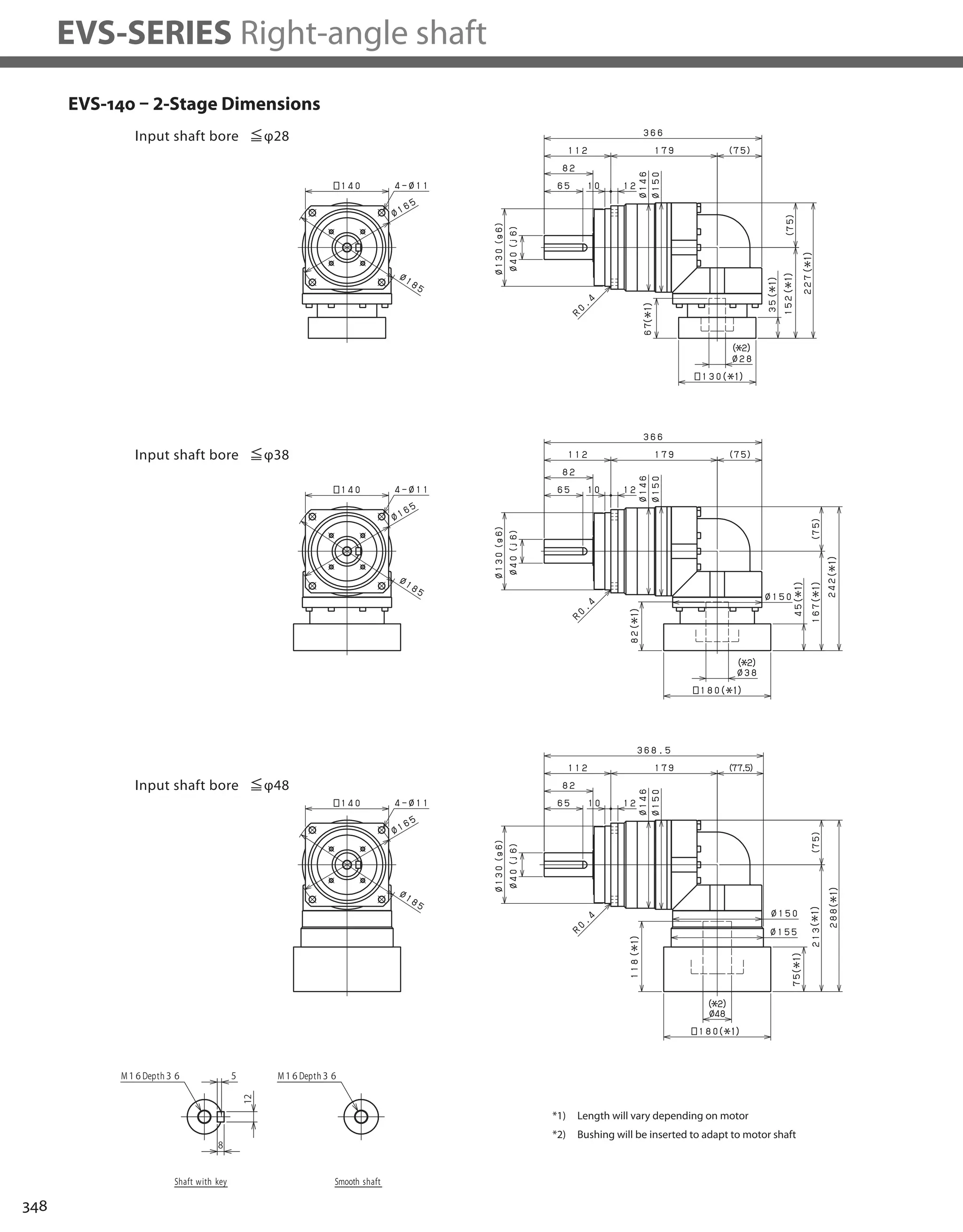


![352
EVS-SERIES Right-angle shaft
EVS-180 – 2-Stage Specifications
EVS-180 – 3-Stage Specifications
Frame Size 180
Stage 2-Stage
Ratio Units Note 3 4 5 6 7 8 9 10
Nominal Output Torque [Nm] *1 400 575 600 600 600 600 400 400
Maximum Acceleration Torque [Nm] *2 575 770 960 1120 1120 1120 775 775
Emergency Stop Torque [Nm] *3 1300 1700 2000 2500 2500 2500 2000 2000
Nominal Input Speed [rpm] *4 1500
Maximum Input Speed [rpm] *5 3000
No Load Running Torque [Nm] *6 10.8
Permitted Radial Load [N] *7 12000 13000 14000 15000 16000 17000 17000 18000
Permitted Axial Load [N] *8 16000 17000 17000 17000 17000 17000 17000 17000
Maximum Radial Load [N] *9 19000
Maximum Axial Load [N] *10 17000
Moment of Inertia (≤Ø 28) [kgcm2] -- -- -- -- -- -- -- -- --
Moment of Inertia (≤Ø 38) [kgcm2] -- 92.00 76.72 71.23 68.28 66.08 65.00 64.38 64.10
Moment of Inertia (≤Ø 48) [kgcm2] -- 126.9 111.6 106.1 103.1 100.9 99.86 99.25 98.97
Moment of Inertia (≤ Ø 65) [kgcm2] -- 212.5 197.2 191.7 188.7 186.6 185.5 184.9 184.6
Efficiency [%] *11 93
Torsional Rigidity [Nm/arcmin] *12 175
Maximum Torsional Backlash [Arc-min] -- ≤ 6
Noise Level [dB] *13 ≤ 85
Protection Class -- *14 IP54 (IP65)
Ambient Temperature [°C] -- 0-40
Permitted Housing Temperature [°C] -- 90
Weight [kg] *15 52
Frame Size 180
Stage 3-Stage
Ratio Units Note 15 16 20 25 28 30 35 40
Nominal Output Torque [Nm] *1 400 555 600 600 600 400 600 600
Maximum Acceleration Torque [Nm] *2 775 1120 1120 1120 1120 775 1120 1120
Emergency Stop Torque [Nm] *3 2000 2500 2500 2500 2500 2000 2500 2500
Nominal Input Speed [rpm] *4 1500
Maximum Input Speed [rpm] *5 3000
No Load Running Torque [Nm] *6 4.7
Permitted Radial Load [N] *7 19000 19000 19000 19000 19000 19000 19000 19000
Permitted Axial Load [N] *8 17000 17000 17000 17000 17000 17000 17000 17000
Maximum Radial Load [N] *9 19000
Maximum Axial Load [N] *10 17000
Moment of Inertia (≤Ø 28) [kgcm2] -- 11.42 12.03 11.11 10.96 11.57 10.31 10.82 10.23
Moment of Inertia (≤Ø 38) [kgcm2] -- 20.21 20.82 19.90 19.74 20.36 19.10 19.60 19.02
Moment of Inertia (≤Ø 48) [kgcm2] -- 25.03 25.64 24.72 24.56 25.18 23.92 24.42 23.84
Moment of Inertia (≤ Ø 65) [kgcm2] -- -- -- -- -- -- -- -- --
Efficiency [%] *11 88
Torsional Rigidity [Nm/arcmin] *12 175
Maximum Torsional Backlash [Arc-min] -- ≤ 9
Noise Level [dB] *13 ≤ 85
Protection Class -- *14 IP54 (IP65)
Ambient Temperature [°C] -- 0-40
Permitted Housing Temperature [°C] -- 90
Weight [kg] *15 39](https://image.slidesharecdn.com/shimpohighprecisioncatalog-140807090507-phpapp01/75/Shimpo-high-precision-catalog-354-2048.jpg)
![353
EVS
EVS-180 – 3-Stage Specifications
Frame Size 180
Stage 3-Stage
Ratio Units Note 45 50 60 70 80 90 100
Nominal Output Torque [Nm] *1 400 600 600 600 600 400 400
Maximum Acceleration Torque [Nm] *2 775 1120 1120 1120 1120 775 775
Emergency Stop Torque [Nm] *3 2000 2500 2500 2500 2500 2000 2000
Nominal Input Speed [rpm] *4 1500
Maximum Input Speed [rpm] *5 3000
No Load Running Torque [Nm] *6 4.7
Permitted Radial Load [N] *7 19000 19000 19000 19000 19000 19000 19000
Permitted Axial Load [N] *8 17000 17000 17000 17000 17000 17000 17000
Maximum Radial Load [N] *9 19000
Maximum Axial Load [N] *10 17000
Moment of Inertia (≤Ø 28) [kgcm2] -- 10.76 10.19 10.17 10.16 10.15 10.14 10.14
Moment of Inertia (≤Ø 38) [kgcm2] -- 19.54 18.98 18.96 18.94 18.94 18.93 18.93
Moment of Inertia (≤Ø 48) [kgcm2] -- 24.36 23.80 23.78 23.77 23.76 23.75 23.75
Moment of Inertia (≤ Ø 65) [kgcm2] -- -- -- -- -- -- -- --
Efficiency [%] *11 88
Torsional Rigidity [Nm/arcmin] *12 175
Maximum Torsional Backlash [Arc-min] -- ≤ 9
Noise Level [dB] *13 ≤ 85
Protection Class -- *14 IP54 (IP65)
Ambient Temperature [°C] -- 0-40
Permitted Housing Temperature [°C] -- 90
Weight [kg] *15 39
*1) At nominal input speed, service life is 20,000 hours
*2) The maximum torque when starting or stopping operation
*3) The maximum torque allowed under a stress situation (Permitted 1,000 times during service life)
*4) The average input speed
*5) The maximum intermittent input speed
*6) This is the torque at no load applied on the input shaft. The input speed is 1500 rpm for EVS180
*7) At this load and nominal input speed, service life will be 20,000 hours. (The radial load applied to the output side bearing)
*8) At this load and nominal input speed, service life will be 20,000 hours. (The axial load applied to the output shaft center)
*9) The maximum radial load that the reducer can accept
*10) The maximum axial load that the reducer can accept
*11) The efficiency at the nominal torque rating
*12) This does not include the lost motion
*13) Contact NIDEC-SHIMPO for the testing conditions and environment
*14) IP65 (wash-down) is available as an option. Contact NIDEC-SHIMPO for more details and our food grade options
*15) The weight may vary slightly between models](https://image.slidesharecdn.com/shimpohighprecisioncatalog-140807090507-phpapp01/75/Shimpo-high-precision-catalog-355-2048.jpg)
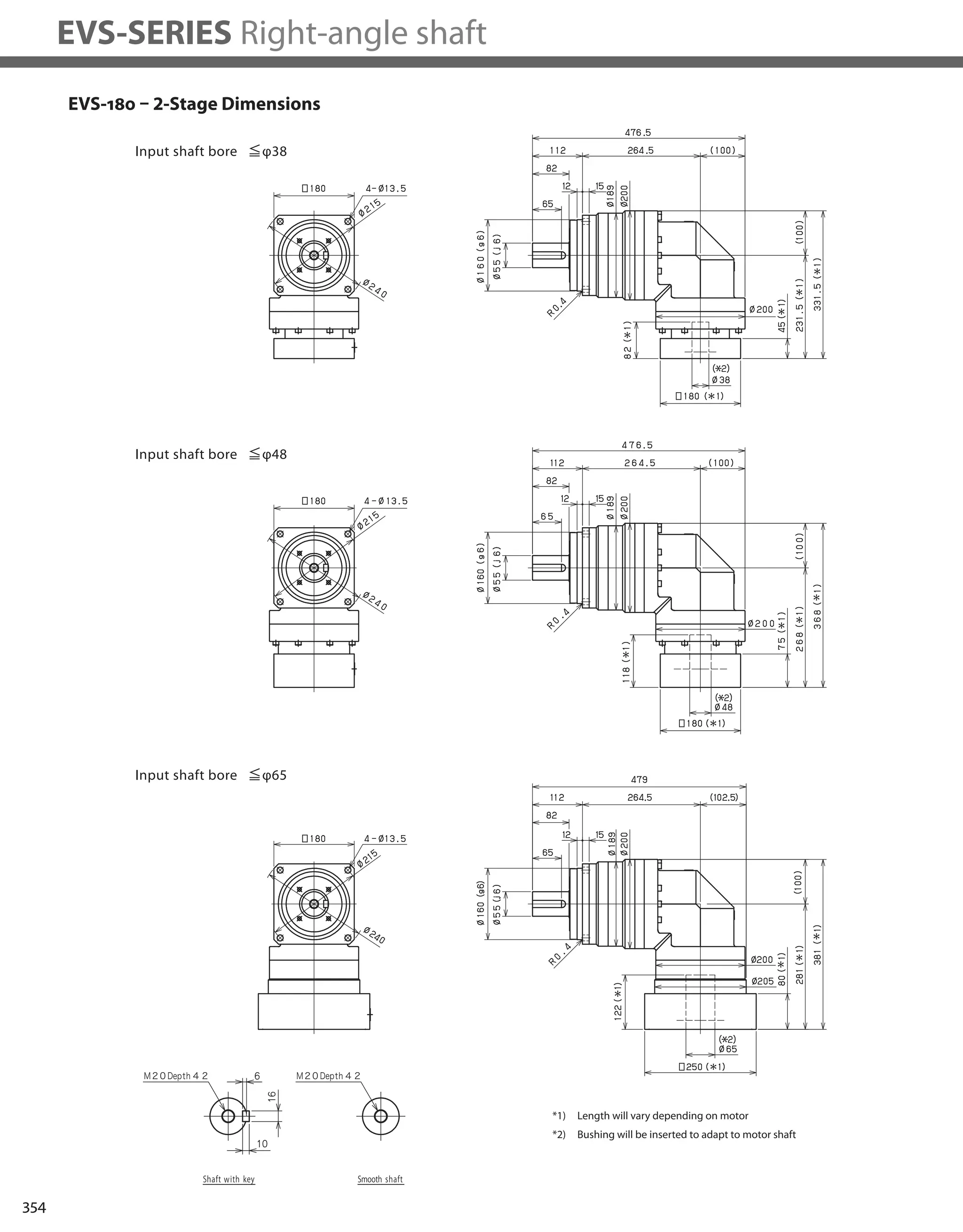
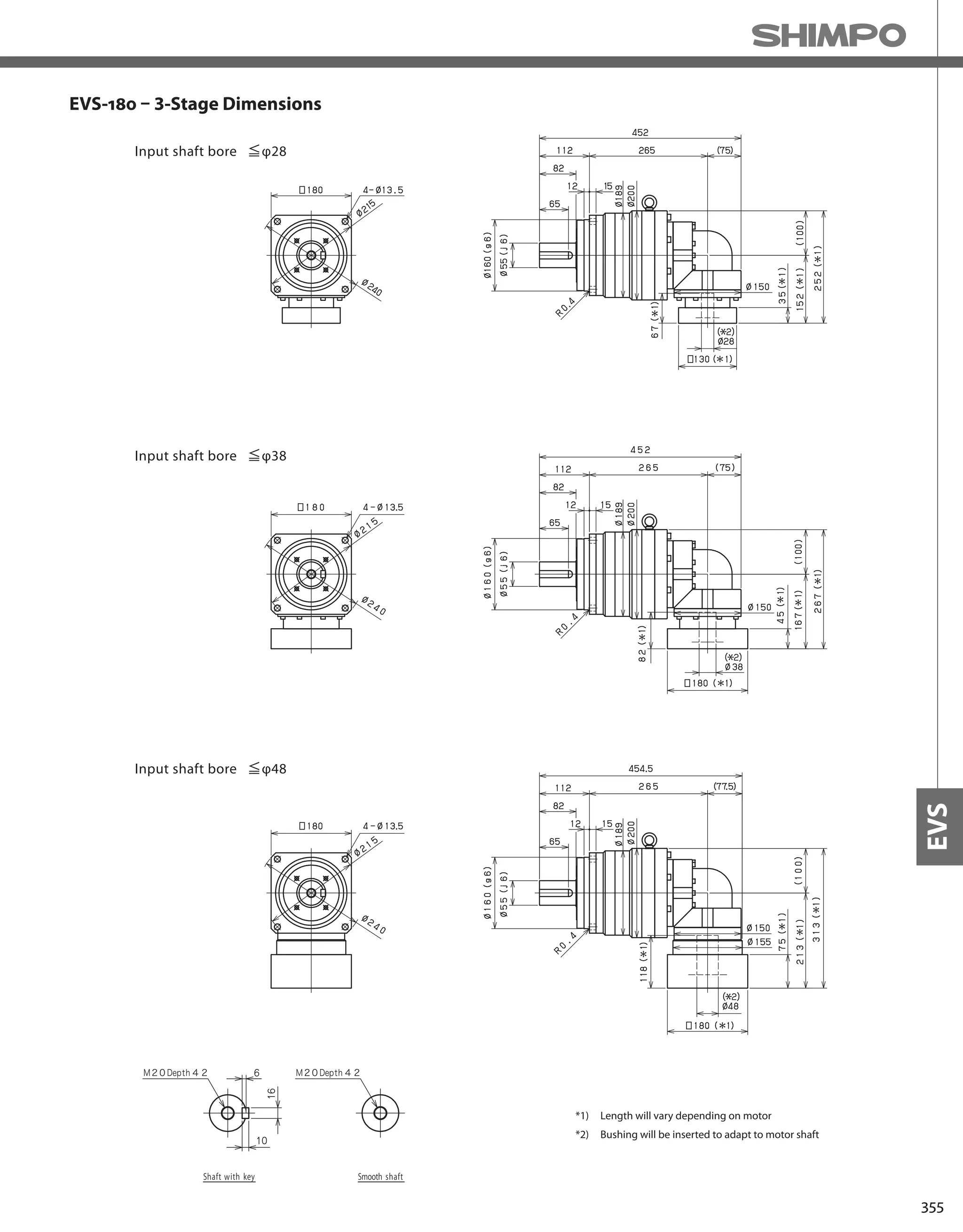
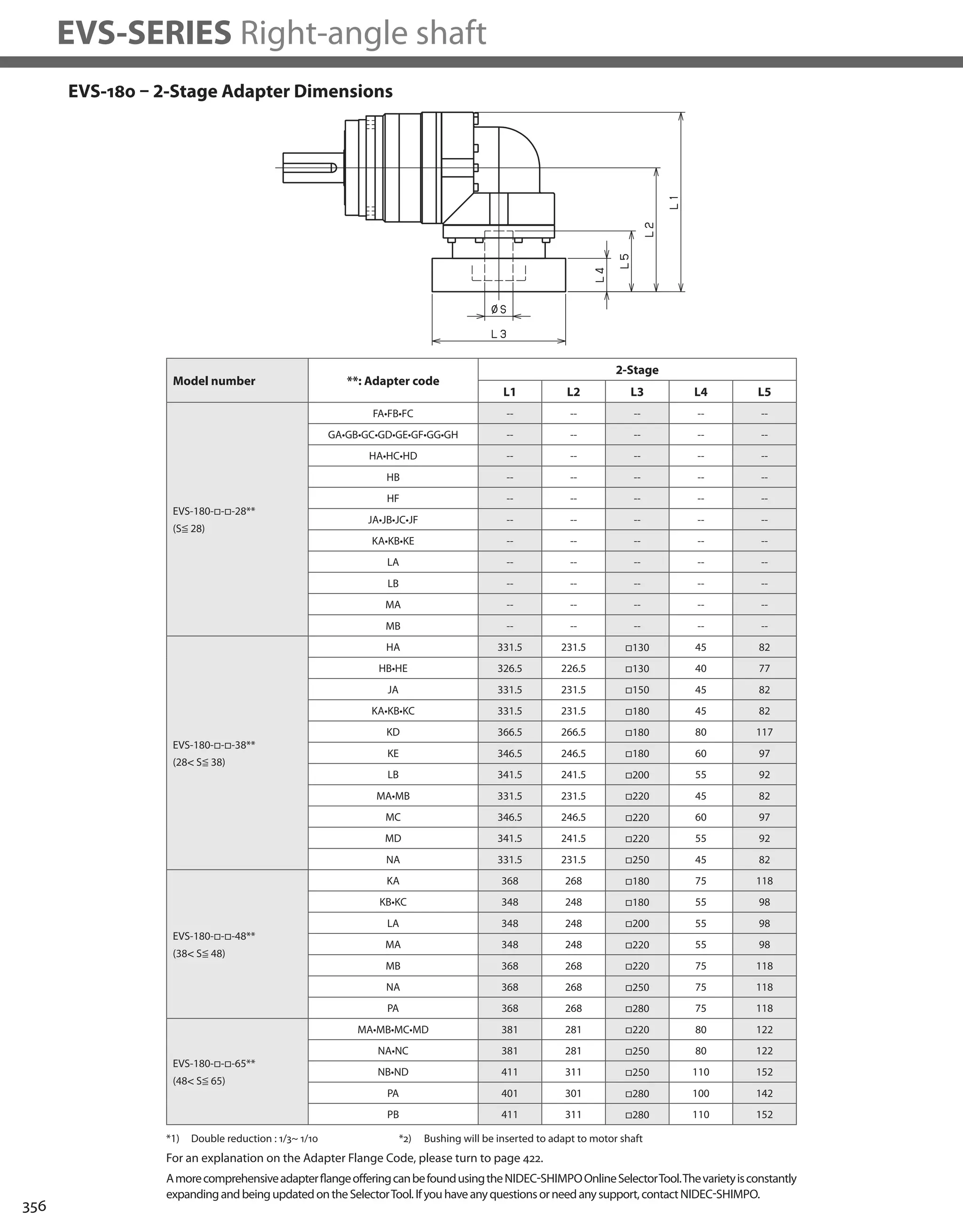
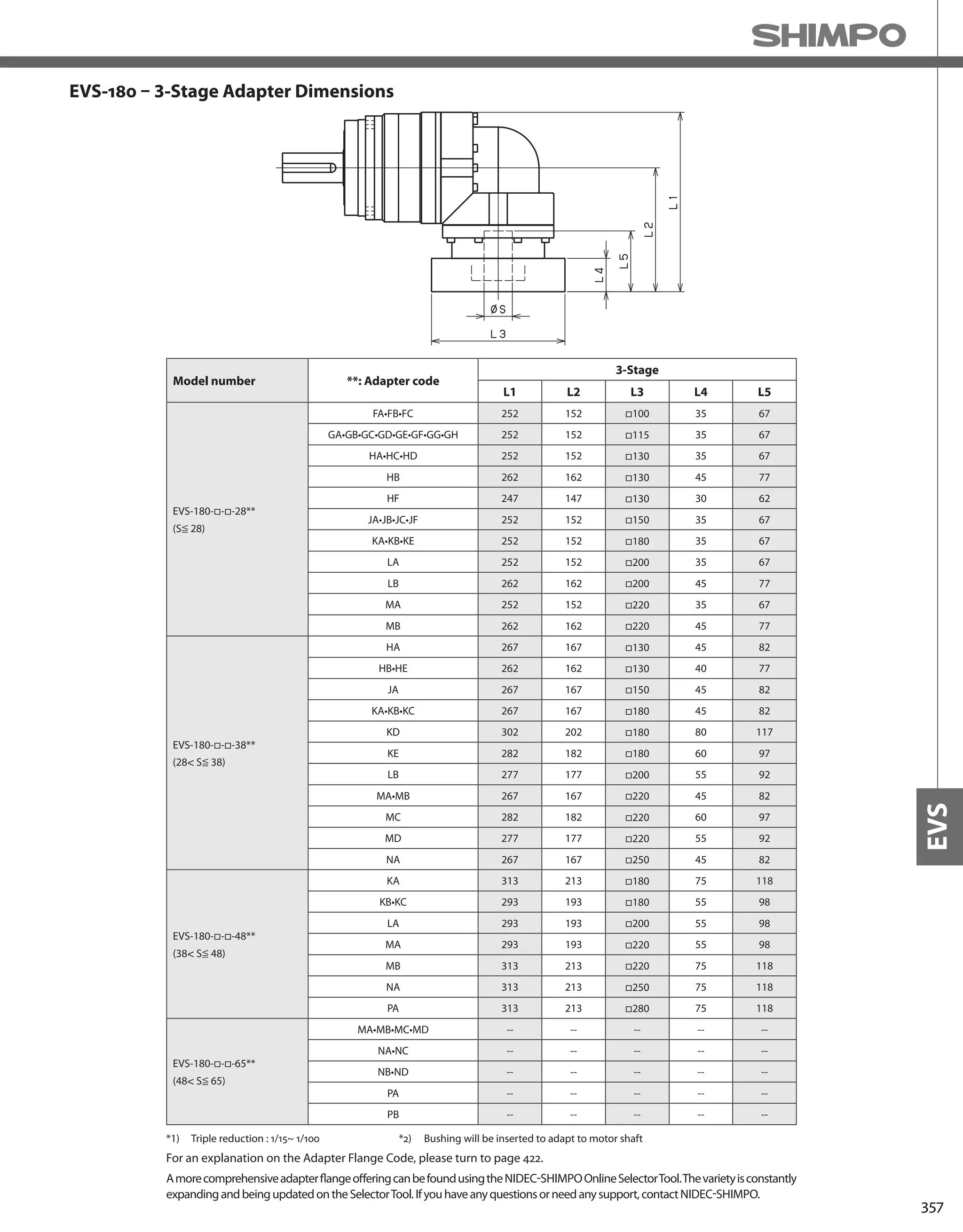
![358
EVS-SERIES Right-angle shaft
EVS-210 – 2-Stage Specifications
EVS-210 – 3-Stage Specifications
Frame Size 210
Stage 2-Stage
Ratio Units Note 3 4 5 6 7 8 9 10
Nominal Output Torque [Nm] *1 575 765 960 1150 1200 1200 800 800
Maximum Acceleration Torque [Nm] *2 1015 1355 1695 1840 1840 1760 1520 1280
Emergency Stop Torque [Nm] *3 2500 3300 4000 4500 4500 4500 3600 3600
Nominal Input Speed [rpm] *4 1000
Maximum Input Speed [rpm] *5 2000
No Load Running Torque [Nm] *6 14.5
Permitted Radial Load [N] *7 17000 18000 20000 21000 22000 23000 24000 24000
Permitted Axial Load [N] *8 22000 22000 22000 22000 22000 22000 22000 22000
Maximum Radial Load [N] *9 24000
Maximum Axial Load [N] *10 22000
Moment of Inertia (≤Ø 38) [kgcm2] -- -- -- -- -- -- -- -- --
Moment of Inertia (≤Ø 48) [kgcm2] -- 149.7 123.8 113.9 108.5 105.0 103.0 101.7 101.1
Moment of Inertia (≤ Ø 65) [kgcm2] -- 224.9 199.0 189.1 183.7 180.3 178.2 176.9 176.3
Efficiency [%] *11 93
Torsional Rigidity [Nm/arcmin] *12 400
Maximum Torsional Backlash [Arc-min] -- ≤ 6
Noise Level [dB] *13 ≤ 85
Protection Class -- *14 IP54 (IP65)
Ambient Temperature [°C] -- 0-40
Permitted Housing Temperature [°C] -- 90
Weight [kg] *15 71
Frame Size 210
Stage 3-Stage
Ratio Units Note 15 16 20 25 28 30 35 40
Nominal Output Torque [Nm] *1 800 1200 1200 1200 1200 800 1200 1200
Maximum Acceleration Torque [Nm] *2 1280 1840 1840 1840 1840 1280 1840 1840
Emergency Stop Torque [Nm] *3 3600 4500 4500 4500 4500 3600 4500 4500
Nominal Input Speed [rpm] *4 1000
Maximum Input Speed [rpm] *5 2000
No Load Running Torque [Nm] *6 10.2
Permitted Radial Load [N] *7 24000 24000 24000 24000 24000 24000 24000 24000
Permitted Axial Load [N] *8 22000 22000 22000 22000 22000 22000 22000 22000
Maximum Radial Load [N] *9 24000
Maximum Axial Load [N] *10 22000
Moment of Inertia (≤Ø 38) [kgcm2] -- 36.39 37.30 35.79 35.49 36.41 34.41 35.22 34.26
Moment of Inertia (≤Ø 48) [kgcm2] -- 66.21 67.12 65.61 65.31 66.23 64.23 65.04 64.08
Moment of Inertia (≤ Ø 65) [kgcm2] -- -- -- -- -- -- -- -- --
Efficiency [%] *11 88
Torsional Rigidity [Nm/arcmin] *12 400
Maximum Torsional Backlash [Arc-min] -- ≤ 9
Noise Level [dB] *13 ≤ 85
Protection Class -- *14 IP54 (IP65)
Ambient Temperature [°C] -- 0-40
Permitted Housing Temperature [°C] -- 90
Weight [kg] *15 73](https://image.slidesharecdn.com/shimpohighprecisioncatalog-140807090507-phpapp01/75/Shimpo-high-precision-catalog-360-2048.jpg)
![359
EVS
EVS-210 – 3-Stage Specifications
Frame Size 210
Stage 3-Stage
Ratio Units Note 45 50 60 70 80 90 100
Nominal Output Torque [Nm] *1 800 1200 1200 1200 1200 800 800
Maximum Acceleration Torque [Nm] *2 1040 1840 1840 1840 1440 1040 960
Emergency Stop Torque [Nm] *3 3600 4500 4500 4500 4500 3600 3600
Nominal Input Speed [rpm] *4 1000
Maximum Input Speed [rpm] *5 2000
No Load Running Torque [Nm] *6 10.2
Permitted Radial Load [N] *7 24000 24000 24000 24000 24000 24000 24000
Permitted Axial Load [N] *8 22000 22000 22000 22000 22000 22000 22000
Maximum Radial Load [N] *9 24000
Maximum Axial Load [N] *10 22000
Moment of Inertia (≤Ø 38) [kgcm2] -- 35.11 34.18 34.14 34.12 34.10 34.09 34.08
Moment of Inertia (≤Ø 48) [kgcm2] -- 64.92 64.00 63.96 63.93 63.92 63.90 63.90
Moment of Inertia (≤ Ø 65) [kgcm2] -- -- -- -- -- -- -- --
Efficiency [%] *11 88
Torsional Rigidity [Nm/arcmin] *12 400
Maximum Torsional Backlash [Arc-min] -- ≤ 9
Noise Level [dB] *13 ≤ 85
Protection Class -- *14 IP54 (IP65)
Ambient Temperature [°C] -- 0-40
Permitted Housing Temperature [°C] -- 90
Weight [kg] *15 73
*1) At nominal input speed, service life is 20,000 hours
*2) The maximum torque when starting or stopping operation
*3) The maximum torque allowed under a stress situation (Permitted 1,000 times during service life)
*4) The average input speed
*5) The maximum intermittent input speed
*6) This is the torque at no load applied on the input shaft. The input speed is 1000 rpm for EVS210
*7) At this load and nominal input speed, service life will be 20,000 hours. (The radial load applied to the output side bearing)
*8) At this load and nominal input speed, service life will be 20,000 hours. (The axial load applied to the output shaft center)
*9) The maximum radial load that the reducer can accept
*10) The maximum axial load that the reducer can accept
*11) The efficiency at the nominal torque rating
*12) This does not include the lost motion
*13) Contact NIDEC-SHIMPO for the testing conditions and environment
*14) IP65 (wash-down) is available as an option. Contact NIDEC-SHIMPO for more details and our food grade options
*15) The weight may vary slightly between models](https://image.slidesharecdn.com/shimpohighprecisioncatalog-140807090507-phpapp01/75/Shimpo-high-precision-catalog-361-2048.jpg)
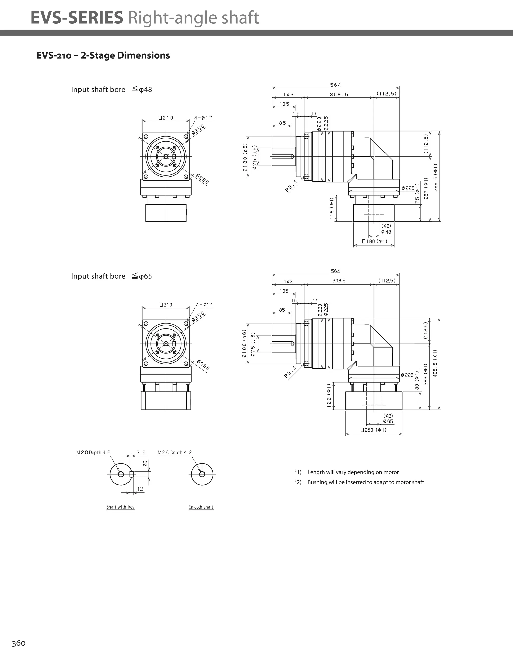


![364
EVS-SERIES Right-angle shaft
EVS-240 – 2-Stage Specifications
EVS-240 – 3-Stage Specifications
Frame Size 240
Stage 2-Stage
Ratio Units Note 3 4 5 6 7 8 9 10
Nominal Output Torque [Nm] *1 1005 1340 1680 1920 1920 1920 1280 1280
Maximum Acceleration Torque [Nm] *2 2000 2960 2960 2960 2960 2880 2400 2080
Emergency Stop Torque [Nm] *3 4000 5400 6500 7200 7200 7200 5400 5400
Nominal Input Speed [rpm] *4 1000
Maximum Input Speed [rpm] *5 2000
No Load Running Torque [Nm] *6 25.3
Permitted Radial Load [N] *7 21000 22000 24000 25000 26000 28000 29000 29000
Permitted Axial Load [N] *8 27000 27000 27000 27000 27000 27000 27000 27000
Maximum Radial Load [N] *9 30000
Maximum Axial Load [N] *10 27000
Moment of Inertia (≤Ø 48) [kgcm2] -- -- -- -- -- -- -- -- --
Moment of Inertia (≤ Ø 65) [kgcm2] -- 217.5 156.7 134.5 122.4 112.9 108.3 105.5 104.0
Efficiency [%] *11 93
Torsional Rigidity [Nm/arcmin] *12 550
Maximum Torsional Backlash [Arc-min] -- ≤ 6
Noise Level [dB] *13 ≤ 85
Protection Class -- *14 IP54 (IP65)
Ambient Temperature [°C] -- 0-40
Permitted Housing Temperature [°C] -- 90
Weight [kg] *15 122
Frame Size 240
Stage 3-Stage
Ratio Units Note 15 16 20 25 28 30 35 40
Nominal Output Torque [Nm] *1 1280 1920 1920 1920 1920 1280 1920 1920
Maximum Acceleration Torque [Nm] *2 2000 2960 2960 2960 2960 2000 2960 2960
Emergency Stop Torque [Nm] *3 5400 7200 7200 7200 7200 5400 7200 7200
Nominal Input Speed [rpm] *4 1000
Maximum Input Speed [rpm] *5 2000
No Load Running Torque [Nm] *6 16.4
Permitted Radial Load [N] *7 30000 30000 30000 30000 30000 30000 30000 30000
Permitted Axial Load [N] *8 27000 27000 27000 27000 27000 27000 27000 27000
Maximum Radial Load [N] *9 30000
Maximum Axial Load [N] *10 27000
Moment of Inertia (≤Ø 48) [kgcm2] -- 40.47 42.59 39.21 38.59 40.73 35.09 38.02 34.78
Moment of Inertia (≤ Ø 65) [kgcm2] -- -- -- -- -- -- -- -- --
Efficiency [%] *11 88
Torsional Rigidity [Nm/arcmin] *12 550
Maximum Torsional Backlash [Arc-min] -- ≤ 9
Noise Level [dB] *13 ≤ 85
Protection Class -- *14 IP54 (IP65)
Ambient Temperature [°C] -- 0-40
Permitted Housing Temperature [°C] -- 90
Weight [kg] *15 113](https://image.slidesharecdn.com/shimpohighprecisioncatalog-140807090507-phpapp01/75/Shimpo-high-precision-catalog-366-2048.jpg)
![365
EVS
EVS-240 – 3-Stage Specifications
Frame Size 240
Stage 3-Stage
Ratio Units Note 45 50 60 70 80 90 100
Nominal Output Torque [Nm] *1 1280 1920 1920 1920 1920 1280 1280
Maximum Acceleration Torque [Nm] *2 1680 2960 2960 2960 2160 1680 1440
Emergency Stop Torque [Nm] *3 5400 7200 7200 7200 7200 5400 5400
Nominal Input Speed [rpm] *4 1000
Maximum Input Speed [rpm] *5 2000
No Load Running Torque [Nm] *6 16.4
Permitted Radial Load [N] *7 30000 30000 30000 30000 30000 30000 30000
Permitted Axial Load [N] *8 27000 27000 27000 27000 27000 27000 27000
Maximum Radial Load [N] *9 30000
Maximum Axial Load [N] *10 27000
Moment of Inertia (≤Ø 48) [kgcm2] -- 37.78 34.62 34.53 34.48 34.45 34.42 34.41
Moment of Inertia (≤ Ø 65) [kgcm2] -- -- -- -- -- -- -- --
Efficiency [%] *11 88
Torsional Rigidity [Nm/arcmin] *12 550
Maximum Torsional Backlash [Arc-min] -- ≤ 9
Noise Level [dB] *13 ≤ 85
Protection Class -- *14 IP54 (IP65)
Ambient Temperature [°C] -- 0-40
Permitted Housing Temperature [°C] -- 90
Weight [kg] *15 113
*1) At nominal input speed, service life is 20,000 hours
*2) The maximum torque when starting or stopping operation
*3) The maximum torque allowed under a stress situation (Permitted 1,000 times during service life)
*4) The average input speed
*5) The maximum intermittent input speed
*6) This is the torque at no load applied on the input shaft. The input speed is 1000 rpm for EVS210
*7) At this load and nominal input speed, service life will be 20,000 hours. (The radial load applied to the output side bearing)
*8) At this load and nominal input speed, service life will be 20,000 hours. (The axial load applied to the output shaft center)
*9) The maximum radial load that the reducer can accept
*10) The maximum axial load that the reducer can accept
*11) The efficiency at the nominal torque rating
*12) This does not include the lost motion
*13) Contact NIDEC-SHIMPO for the testing conditions and environment
*14) IP65 (wash-down) is available as an option. Contact NIDEC-SHIMPO for more details and our food grade options
*15) The weight may vary slightly between models](https://image.slidesharecdn.com/shimpohighprecisioncatalog-140807090507-phpapp01/75/Shimpo-high-precision-catalog-367-2048.jpg)
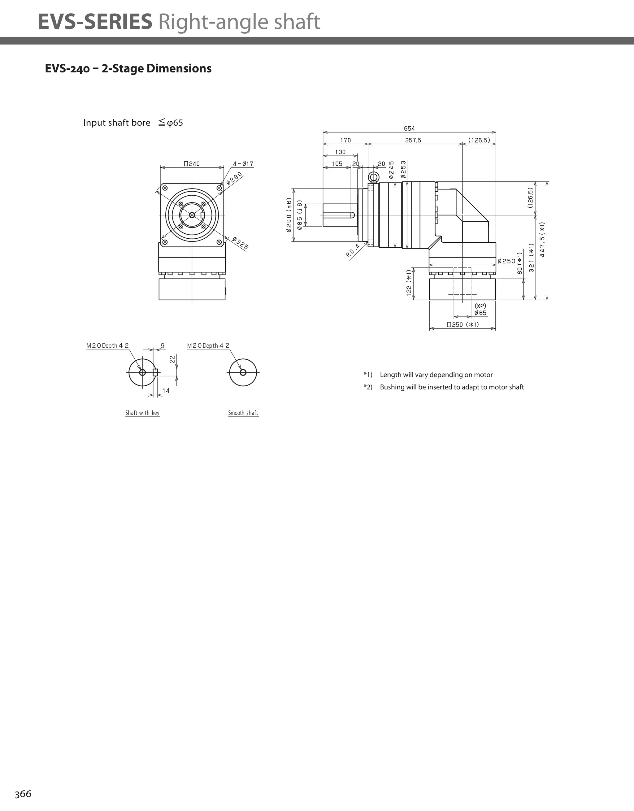


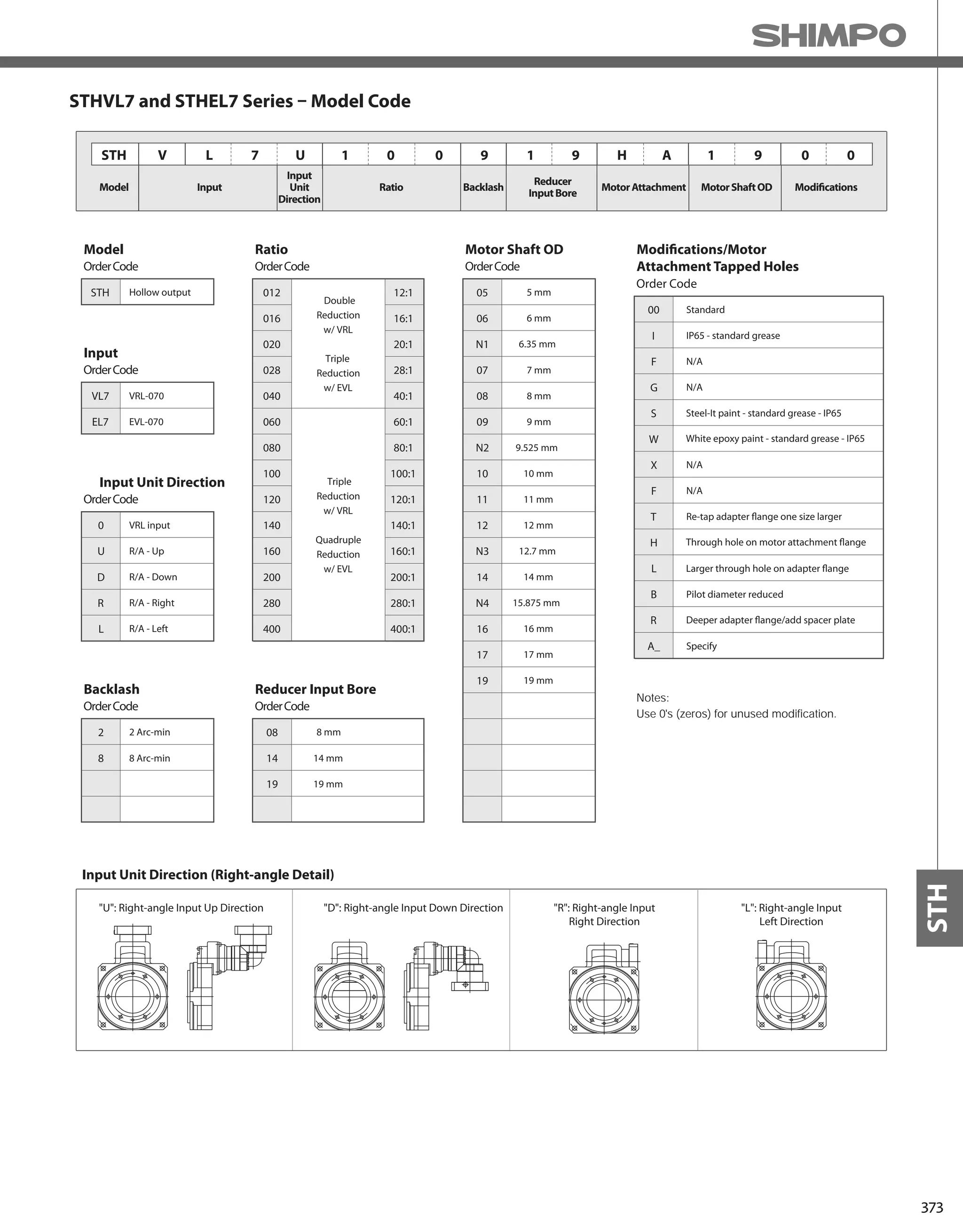
![374
STH-SERIES Hollow output rotary actuators
226
170
85
60
24
18 98.8
6-M8x1.25
2-Ø6(H7)
Output Shaft
L
9
4-Ø11
Ø135(h8)
Ø176(h8)
Ø104(H8)
Ø85(HollowDia)
15
45
Ø120
Ø205
30°
12 Depth
8 Depth
30°
STHVL7 2-Stage & 3-Stage Specifications
STHVL7 2-Stage & 3-Stage Dimensions
Frame Size STHVL7
Stage Units Notes 2-Stage 3-Stage
Ratio -- *1 12:1 16:1 20:1 28:1 40:1 60:1 80:1
Nominal Torque 1 [Nm] *2 65 85 85 85 68 68 85
Acceleration Torque [Nm] -- 126 170 170 170 133 133 170
Emergency Stop Torque [Nm] -- 240 240 240 240 240 240 240
Nominal Input Speed [rpm] -- 3000 3000
Max. Input Speed [rpm] -- 6000 6000
Moment of Inertia (≤Ø 8) [kgcm2] *3 1.109 0.640 0.426 0.240 0.143 0.094 0.076
Moment of Inertia (≤Ø 14) [kgcm2] *3 1.189 0.715 0.509 0.318 0.227 0.179 0.152
Moment of Inertia (≤Ø 19) [kgcm2] *3 1.399 0.925 0.709 0.528 0.427 0.389 0.372
Backlash [arc-min] -- 2 2
Accuracy [arc-sec] -- ±60 ±60
Torsional Stiffness [Nm/arc-min] -- 7.6 7.6
Weight [kg] -- 7.6 7.8
Max. Axial Load [N] -- 4000 4000
Max. Radial Load [N] -- 5000 5000
Max. Tilting Moment Load [Nm] -- 200 200
Max. Surface Runout [mm] -- 0.070 0.070
Max. Deflection [mm] -- 0.70 0.70
Efficiency [%] -- 86 86 90 90 90 86 86
Noise Level [dB] -- 72 72 65 65 65 65 65
Max. Ambient Temperature °C -- 0-40 0-40
Max. Surface Temperature °C -- 90 90
Lubrication -- -- Grease Grease
Protection -- *4 IP54 (IP65) IP54 (IP65)
Unit Life hr -- 20000 20000
*1) Contact NIDEC-SHIMPO for more optional ratios
*2) At nominal input speed
*3) At input shaft
*4) IP65 (wash-down) is available as an option. Contact NIDEC-SHIMPO for more details and our food grade options](https://image.slidesharecdn.com/shimpohighprecisioncatalog-140807090507-phpapp01/75/Shimpo-high-precision-catalog-376-2048.jpg)
![375
STH
226
170
85
60
24
18 98.8
6-M8x1.25
2-Ø6(H7)
Output Shaft
L
9
4-Ø11
Ø135(h8)
Ø176(h8)
Ø104(H8)
Ø85(HollowDia)
15
45
Ø120
Ø205
30°
12 Depth
8 Depth
30°
STHVL7 3-Stage Specifications
STHVL7 3-Stage Dimensions
Frame Size STHVL7
Stage Units Notes 3-Stage
Ratio -- *1 100:1 120:1 140:1 160:1 200:1 280:1 400:1
Nominal Torque 1 [Nm] *2 85 68 85 85 85 85 68
Acceleration Torque [Nm] -- 170 133 170 170 170 170 133
Emergency Stop Torque [Nm] -- 240 240 240 240 240 240 240
Nominal Input Speed [rpm] -- 3000
Max. Input Speed [rpm] -- 6000
Moment of Inertia (≤Ø 8) [kgcm2] *3 0.067 0.059 0.060 0.054 0.052 0.051 0.050
Moment of Inertia (≤Ø 14) [kgcm2] *3 0.144 0.140 0.137 0.135 0.133 0.132 0.131
Moment of Inertia (≤Ø 19) [kgcm2] *3 0.364 0.350 0.357 0.345 0.343 0.342 0.341
Backlash [arc-min] -- 2
Accuracy [arc-sec] -- ±60
Torsional Stiffness [Nm/arc-min] -- 7.6
Weight [kg] -- 7.8
Max. Axial Load [N] -- 4000
Max. Radial Load [N] -- 5000
Max. Tilting Moment Load [Nm] -- 200
Max. Surface Runout [mm] -- 0.070
Max. Deflection [mm] -- 0.70
Efficiency [%] -- 86 86 86 86 86 86 86
Noise Level [dB] -- 65 65 65 65 65 65 65
Max. Ambient Temperature °C -- 0-40
Max. Surface Temperature °C -- 90
Lubrication -- -- Grease
Protection -- *4 IP54 (IP65)
Unit Life hr -- 20000
*1) Contact NIDEC-SHIMPO for more optional ratios
*2) At nominal input speed
*3) At input shaft
*4) IP65 (wash-down) is available as an option. Contact NIDEC-SHIMPO for more details and our food grade options](https://image.slidesharecdn.com/shimpohighprecisioncatalog-140807090507-phpapp01/75/Shimpo-high-precision-catalog-377-2048.jpg)
![376
STH-SERIES Hollow output rotary actuators
226
170
85
Ø135(h8)
Ø176(h8)
Ø104(H8)
Ø85(HollowDia)
L
60
24
18
M
4-Ø11
6-M8x1.25
2-Ø6(H7)
Output Shaft
Ø120
Ø205
15
9
30°
30°
45
12 Depth
8 Depth
STHEL7 2-Stage & 3-Stage Specifications
Frame Size STHEL7
Stage Units Notes 2-Stage 3-Stage
Ratio -- *1 12:1 16:1 20:1 28:1 40:1 60:1 80:1
Nominal Torque 1 [Nm] *2 43 58 84 85 61 61 85
Acceleration Torque [Nm] -- 86 115 152 170 122 122 170
Emergency Stop Torque [Nm] -- 180 234 240 240 204 240 240
Nominal Input Speed [rpm] -- 3000 3000
Max. Input Speed [rpm] -- 6000 6000
Moment of Inertia (≤Ø 8) [kgcm2] *3 1.280 0.811 0.597 0.412 0.314 0.112 0.093
Moment of Inertia (≤Ø 14) [kgcm2] *3 1.355 0.886 0.672 0.487 0.389 0.157 0.138
Moment of Inertia (≤Ø 19) [kgcm2] *3 1.544 1.075 0.862 0.676 0.578 -- --
Backlash [arc-min] -- 8 8
Accuracy [arc-sec] -- ±60 ±60
Torsional Stiffness [Nm/arc-min] -- 7.6 7.6
Weight [kg] -- 8.0 7.8
Max. Axial Load [N] -- 4000 4000
Max. Radial Load [N] -- 5000 5000
Max. Tilting Moment Load [Nm] -- 200 200
Max. Surface Runout [mm] -- 0.070 0.070
Max. Deflection [mm] -- 0.70 0.70
Efficiency [%] -- 84 84 88 88 88 84 84
Noise Level [dB] -- 72 72 65 65 65 65 65
Max. Ambient Temperature °C -- 0-40 0-40
Max. Surface Temperature °C -- 90 90
Lubrication -- -- Grease Grease
Protection -- *4 IP54 (IP65) IP54 (IP65)
Unit Life hr -- 20000 20000
STHEL7 2-Stage & 3-Stage Dimensions
*1) Contact NIDEC-SHIMPO for more optional ratios
*2) At nominal input speed
*3) At input shaft
*4) IP65 (wash-down) is available as an option. Contact NIDEC-SHIMPO for more details and our food
grade options](https://image.slidesharecdn.com/shimpohighprecisioncatalog-140807090507-phpapp01/75/Shimpo-high-precision-catalog-378-2048.jpg)
![377
STH
226
170
85
Ø135(h8)
Ø176(h8)
Ø104(H8)
Ø85(HollowDia)
L
60
24
18
M
4-Ø11
6-M8x1.25
2-Ø6(H7)
Output Shaft
Ø120
Ø205
15
9
30°
30°
45
12 Depth
8 Depth
STHEL7 3-Stage Specifications
Frame Size STHEL7
Stage Units Notes 3-Stage
Ratio -- *1 100:1 120:1 140:1 160:1 200:1 280:1 400:1
Nominal Torque 1 [Nm] *2 85 61 85 85 85 85 61
Acceleration Torque [Nm] -- 170 122 170 170 170 170 122
Emergency Stop Torque [Nm] -- 240 240 240 240 240 240 240
Nominal Input Speed [rpm] -- 3000
Max. Input Speed [rpm] -- 6000
Moment of Inertia (≤Ø 8) [kgcm2] *3 0.085 0.072 0.077 0.066 0.064 0.063 0.062
Moment of Inertia (≤Ø 14) [kgcm2] *3 0.129 0.116 0.122 0.111 0.108 0.106 0.106
Moment of Inertia (≤Ø 19) [kgcm2] *3 -- -- -- -- -- -- --
Backlash [arc-min] -- 8
Accuracy [arc-sec] -- ±60
Torsional Stiffness [Nm/arc-min] -- 7.6
Weight [kg] -- 7.8
Max. Axial Load [N] -- 4000
Max. Radial Load [N] -- 5000
Max. Tilting Moment Load [Nm] -- 200
Max. Surface Runout [mm] -- 0.070
Max. Deflection [mm] -- 0.70
Efficiency [%] -- 84 84 84 84 84 84 84
Noise Level [dB] -- 65 65 65 65 65 65 65
Max. Ambient Temperature °C -- 0-40
Max. Surface Temperature °C -- 90
Lubrication -- -- Grease
Protection -- *4 IP54 (IP65)
Unit Life hr -- 20000
STHEL7 3-Stage Dimensions
*1) Contact NIDEC-SHIMPO for more optional ratios
*2) At nominal input speed
*3) At input shaft
*4) IP65 (wash-down) is available as an option. Contact NIDEC-SHIMPO for more details and our food
grade options](https://image.slidesharecdn.com/shimpohighprecisioncatalog-140807090507-phpapp01/75/Shimpo-high-precision-catalog-379-2048.jpg)


![381
STR
STR-Series – Model Code
Contact us for additional information or refer to our online reducer selection tool.
Selection tool www.nidec-shimpo.co.jp/selection/eng
* Adapter flange code
Modifications
STR 1 0 0 0 8 0 E R
Gearbox mount side (Right [R], Left [L])
Input Reducer type (Inline [V], Right-angle [E], None [N])
(Variety ranging from 15:1 - 2000:1)Reduction ratio
Actuator size (040, 063, 080, 100, 125, 160, 250)
Model name STR product
1 4 B K 1 2 0 0
*1) Adapter flange code
Adapter flange code varies depending on the motor.](https://image.slidesharecdn.com/shimpohighprecisioncatalog-140807090507-phpapp01/75/Shimpo-high-precision-catalog-383-2048.jpg)
![382
STR-SERIES Rotary indexer
STR-040V – 1-Stage and 2-Stage Specifications with VRSF-B
*1) At nominal input speed
*2) Speeds are at the actuator input. Limits when used with additional gearbox are higher
*3) At input shaft
*4) IP65 (wash-down) is available as an option. Contact NIDEC-SHIMPO for more details and our food grade options
Frame Size 040V
Stage 1-Stage 2-Stage
Ratio Units Notes 15 45 75 135
Nominal Torque [Nm] *1 27 27 27 27
Acceleration Torque [Nm] -- 58 58 58 58
No Load Torque [Nm] *1 0.5 0.2 0.2 0.2
Nominal Input Speed [rpm] *2 900 2700 3000 3000
Maximum Input Speed [rpm] *2 3000 5000 5000 5000
Reflected Inertia (Single) [kg-m2x10-4] *3 0.292 -- -- --
Reflected Inertia (≤Ø 8) [kg-m2x10-4] *3 -- 0.082 0.06 0.053
Reflected Inertia (≤Ø 14) [kg-m2x10-4] *3 -- 0.151 0.131 0.121
Backlash [arc-min] -- 0 0 0 0
Angular Transmission Accuracy [arc-min] -- ≤ 1.5 ≤ 1.5
Angular Repeatability Accuracy [arc-min] -- ± 0.2 ± 0.2
Surface Runout [μm (max)] -- 10 10 10 10
Weight [kg] -- 2.5 3.2 3.2 3.2
Maximum Axial Load [N] -- 999 999 999 999
Maximum Radial Load [N] -- 669 669 669 669
Maximum Tilting Moment Load [Nm] -- 33 33 33 33
Efficiency [%] -- 80 76 76 76
Protection Class -- *4 IP54 (IP65)
6-M5 Depth10
V
47.5
95
0.5
62
65
Ø40
Ø55
Ø30h7
Ø25
70
31
115
434032
1008
72
Ø25
17.5
21 ±0.05
27
122
40.5 ±0.1
81 ±0.03
65±0.1
INPUT FLANGE
OUTPUT TABLE SURFACE
Depth10
S
W
R
V
Depth10
***2-Ø5 H7 Depth8
(SURFACE V&W)
3-Ø6.9 DRILL THRU, Counterbore Ø11 Depth 6.5
3-M8 Depth 15
R
U
T
***2-Ø5 H7 Depth8
VRSF-B
Ø42
Ø26
S
U
Tdc
ab
11.5
52 5
6101
52
**
S
W
V
R
Ø60
4-Ø5.5 DRILL THRU
NOTE:
** Refer to page 22, for VRSF B-Frame dimensions
*** Optional
ROTATION:
a=d
a=c (upon special request)
STR-040 Dimensions with VRSF-B](https://image.slidesharecdn.com/shimpohighprecisioncatalog-140807090507-phpapp01/75/Shimpo-high-precision-catalog-384-2048.jpg)
![383
STR
STR-040V – 3-Stage Specifications with VRSF-B
*1) At nominal input speed
*2) Speeds are at the actuator input. Limits when used with additional gearbox are higher
*3) At input shaft
*4) IP65 (wash-down) is available as an option. Contact NIDEC-SHIMPO for more details and our food grade options
Frame Size 040V
Stage 3-Stage
Ratio Units Notes 225 300 375 525
Nominal Torque [Nm] *1 27 27 27 27
Acceleration Torque [Nm] -- 58 58 58 58
No Load Torque [Nm] *1 0.1 0.1 0.1 0.1
Nominal Input Speed [rpm] *2 3000 3000 3000 3000
Maximum Input Speed [rpm] *2 5000 5000 5000 5000
Reflected Inertia (Single) [kg-m2x10-4] *3 -- -- -- --
Reflected Inertia (≤Ø 8) [kg-m2x10-4] *3 0.058 0.057 0.057 0.053
Reflected Inertia (≤Ø 14) [kg-m2x10-4] *3 0.131 0.131 0.131 0.121
Backlash [arc-min] -- 0 0 0 0
Angular Transmission Accuracy [arc-min] -- ≤ 1.5
Angular Repeatability Accuracy [arc-min] -- ± 0.2
Surface Runout [μm (max)] -- 10 10 10 10
Weight [kg] -- 3.4 3.4 3.4 3.4
Maximum Axial Load [N] -- 999 999 999 999
Maximum Radial Load [N] -- 669 669 669 669
Maximum Tilting Moment Load [Nm] -- 33 33 33 33
Efficiency [%] -- 72 72 72 72
Protection Class -- *4 IP54 (IP65)
6-M5 Depth10
V
47.5
95
0.5
62
65
Ø40
Ø55
Ø30h7
Ø25
70
31
115
434032
1008
72
Ø25
17.5
21 ±0.05
27
122
40.5 ±0.1
81 ±0.03
65±0.1
INPUT FLANGE
OUTPUT TABLE SURFACE
Depth10
S
W
R
V
Depth10
***2-Ø5 H7 Depth8
(SURFACE V&W)
3-Ø6.9 DRILL THRU, Counterbore Ø11 Depth 6.5
3-M8 Depth 15
R
U
T
***2-Ø5 H7 Depth8
VRSF-B
Ø42
Ø26
S
U
Tdc
ab
11.5
52 5
6101
52
**
S
W
V
R
Ø60
4-Ø5.5 DRILL THRU
NOTE:
** Refer to page 22, for VRSF B-Frame dimensions
*** Optional
ROTATION:
a=d
a=c (upon special request)
STR-040 Dimensions with VRSF-B](https://image.slidesharecdn.com/shimpohighprecisioncatalog-140807090507-phpapp01/75/Shimpo-high-precision-catalog-385-2048.jpg)
![384
STR-SERIES Rotary indexer
STR-063V – 2-Stage and 3-Stage Specifications with VRB-060
STR-063V – 1-Stage and 2-Stage Specifications with VRB-060
*1) At nominal input speed
*2) Speeds are at the actuator input. Limits when used with additional gearbox are higher
*3) At input shaft
*4) IP65 (wash-down) is available as an option. Contact NIDEC-SHIMPO for more details and our food grade options
*1) At nominal input speed
*2) Speeds are at the actuator input. Limits when used with additional gearbox are higher
*3) At input shaft
*4) IP65 (wash-down) is available as an option. Contact NIDEC-SHIMPO for more details and our food grade options
Frame Size 063V
Stage 1-Stage 2-Stage
Ratio Units Notes 20 60 80 100 120 140 160 180
Nominal Torque [Nm] *1 69 69 69 69 69 69 69 69
Acceleration Torque [Nm] -- 129 129 129 129 129 129 129 129
No Load Torque [Nm] *1 0.8 0.1 0.1 0.1 0.1 0.1 0.1 0.1
Nominal Input Speed [rpm] *2 800 2400 3000 3000 3000 3000 3000 3000
Maximum Input Speed [rpm] *2 3000 6000 6000 6000 6000 6000 6000 6000
Reflected Inertia (Single) [kg-m2x10-4] *3 0.862 -- -- -- -- -- -- --
Reflected Inertia (≤Ø 8) [kg-m2x10-4] *3 -- 0.142 0.097 0.079 0.070 0.064 0.061 0.059
Reflected Inertia (≤Ø 14) [kg-m2x10-4] *3 -- 0.222 0.172 0.162 0.152 0.142 0.142 0.142
Reflected Inertia (≤Ø 19) [kg-m2x10-4] *3 -- 0.432 0.382 0.362 0.362 0.352 0.352 0.342
Backlash [arc-min] -- 0 0 0 0 0 0 0 0
Angular Transmission Accuracy [arc-min] -- ≤ 1.0 ≤ 1.0
Angular Repeatability Accuracy [arc-min] -- ± 0.1 ± 0.1
Surface Runout [μm (max)] -- 10 10 10 10 10 10 10 10
Weight [kg] -- 5.6 7.0 7.0 7.0 7.0 7.0 7.0 7.0
Maximum Axial Load [N] -- 1657 1657 1657 1657 1657 1657 1657 1657
Maximum Radial Load [N] -- 1359 1359 1359 1359 1359 1359 1359 1359
Maximum Tilting Moment Load [Nm] -- 79 79 79 79 79 79 79 79
Efficiency [%] -- 82 78 78 78 78 78 78 78
Protection Class -- *4 IP54 (IP65)
Frame Size 063V
Stage 2-Stage 3-Stage
Ratio Units Notes 200 300 320 400 500 560 600 700
Nominal Torque [Nm] *1 69 69 69 69 69 69 69 69
Acceleration Torque [Nm] -- 129 129 129 129 129 129 129 129
No Load Torque [Nm] *1 0.1 0.1 0.1 0.1 0.1 0.1 0.1 0.1
Nominal Input Speed [rpm] *2 3000 3000 3000 3000 3000 3000 3000 3000
Maximum Input Speed [rpm] *2 6000 6000 6000 6000 6000 6000 6000 6000
Reflected Inertia (Single) [kg-m2x10-4] *3 -- -- -- -- -- --- --- ---
Reflected Inertia (≤Ø 8) [kg-m2x10-4] *3 0.058 0.057 0.059 0.056 0.055 0.057 0.051 0.055
Reflected Inertia (≤Ø 14) [kg-m2x10-4] *3 0.142 0.142 0.142 0.132 0.132 0.142 0.132 0.132
Reflected Inertia (≤Ø 19) [kg-m2x10-4] *3 0.342 0.352 0.362 0.352 0.352 0.362 0.342 0.352
Backlash [arc-min] -- 0 0 0 0 0 0 0 0
Angular Transmission Accuracy [arc-min] -- ≤ 1.0 ≤ 1.0
Angular Repeatability Accuracy [arc-min] -- ± 0.1 ± 0.1
Surface Runout [μm (max)] -- 10 10 10 10 10 10 10 10
Weight [kg] -- 7.0 7.2 7.2 7.2 7.2 7.2 7.2 7.2
Maximum Axial Load [N] -- 1657 1657 1657 1657 1657 1657 1657 1657
Maximum Radial Load [N] -- 1359 1359 1359 1359 1359 1359 1359 1359
Maximum Tilting Moment Load [Nm] -- 79 79 79 79 79 79 79 79
Efficiency [%] -- 78 74 74 74 74 74 74 74
Protection Class -- *4 IP54 (IP65)](https://image.slidesharecdn.com/shimpohighprecisioncatalog-140807090507-phpapp01/75/Shimpo-high-precision-catalog-386-2048.jpg)
![385
STR
STR-063V – 3-Stage Specifications with VRB-060
*1) At nominal input speed
*2) Speeds are at the actuator input. Limits when used with additional gearbox are higher
*3) At input shaft
*4) IP65 (wash-down) is available as an option. Contact NIDEC-SHIMPO for more details and our food grade options
Frame Size 063V
Stage 3-Stage
Ratio Units Notes 800 900 1000 1200 1400 1600 1800 2000
Nominal Torque [Nm] *1 69 69 69 69 69 69 69 69
Acceleration Torque [Nm] -- 129 129 129 129 129 129 129 129
No Load Torque [Nm] *1 0.1 0.1 0.1 0.1 0.1 0.1 0.1 0.1
Nominal Input Speed [rpm] *2 3000 3000 3000 3000 3000 3000 3000 3000
Maximum Input Speed [rpm] *2 6000 6000 6000 6000 6000 6000 6000 6000
Reflected Inertia (Single) [kg-m2x10-4] *3 --- --- --- --- --- --- --- ---
Reflected Inertia (≤Ø 8) [kg-m2x10-4] *3 0.051 0.055 0.051 0.051 0.051 0.051 0.051 0.051
Reflected Inertia (≤Ø 14) [kg-m2x10-4] *3 0.132 0.132 0.132 0.132 0.132 0.132 0.132 0.132
Reflected Inertia (≤Ø 19) [kg-m2x10-4] *3 0.342 0.352 0.342 0.342 0.342 0.342 0.342 0.342
Backlash [arc-min] -- 0 0 0 0 0 0 0 0
Angular Transmission Accuracy [arc-min] -- ≤ 1.0
Angular Repeatability Accuracy [arc-min] -- ± 0.1
Surface Runout [μm (max)] -- 10 10 10 10 10 10 10 10
Weight [kg] -- 7.2 7.2 7.2 7.2 7.2 7.2 7.2 7.2
Maximum Axial Load [N] -- 1657 1657 1657 1657 1657 1657 1657 1657
Maximum Radial Load [N] -- 1359 1359 1359 1359 1359 1359 1359 1359
Maximum Tilting Moment Load [Nm] -- 79 79 79 79 79 79 79 79
Efficiency [%] -- 74 74 74 74 74 74 74 74
Protection Class -- *4 IP54 (IP65)
STR-063 Dimensions with VRB-060
139.510.5
4-M5 Depth 10
V
Ø70
59 10.5
b a
104
52
10
R
95
606340
163
143
U
V
144.5
24.5
37.5
120
100 10
60
**
VRB-060
***2-Ø5 H7 Depth 8
3-Ø8.6 DRILL THRU, Counterbore Ø14 Depth 8.6
3-M10 Depth 15
(SURFACE V & W)
(SURFACE V & W)
*** Ø5 H7 Depth 8
6-M6 Depth12
c d
Ø75
0.5
Ø70
Ø50Depth10
W
Ø90
Ø60h7
Ø50Depth10
40
70
73
78
OUTPUT TABLE SURFACE
INPUT FLANGE
V
Ø51
±0.03
±0.05
±0.1
±0.1
**
S
W
NOTE:
** Refer to page 92, for VRB-060 dimensions
*** Optional
ROTATION:
a=d
a=c (upon special request)](https://image.slidesharecdn.com/shimpohighprecisioncatalog-140807090507-phpapp01/75/Shimpo-high-precision-catalog-387-2048.jpg)
![386
STR-SERIES Rotary indexer
STR-063E – 1-Stage and 2-Stage Specifications with EVB-060
STR-063E – 2-Stage and 3-Stage Specifications with EVB-060
*1) At nominal input speed
*2) Speeds are at the actuator input. Limits when used with additional gearbox are higher
*3) At input shaft
*4) IP65 (wash-down) is available as an option. Contact NIDEC-SHIMPO for more details and our food grade options
*1) At nominal input speed
*2) Speeds are at the actuator input. Limits when used with additional gearbox are higher
*3) At input shaft
*4) IP65 (wash-down) is available as an option. Contact NIDEC-SHIMPO for more details and our food grade options
Frame Size 063E
Stage 1-Stage 2-Stage
Ratio Units Notes 20 60 80 100 120 140 160 180
Nominal Torque [Nm] *1 69 69 69 69 69 69 69 69
Acceleration Torque [Nm] -- 129 129 129 129 129 129 129 129
No Load Torque [Nm] *1 0.8 0.4 0.4 0.4 0.4 0.4 0.4 0.4
Nominal Input Speed [rpm] *2 800 2400 3000 3000 3000 3000 3000 3000
Maximum Input Speed [rpm] *2 3000 6000 6000 6000 6000 6000 6000 6000
Reflected Inertia (Single) [kg-m2x10-4] *3 0.862 -- -- -- -- -- -- --
Reflected Inertia (≤Ø 8) [kg-m2x10-4] *3 -- 0.311 0.266 0.248 0.239 0.234 0.230 0.228
Reflected Inertia (≤Ø 14) [kg-m2x10-4] *3 -- 0.386 0.341 0.323 0.314 0.309 0.305 0.303
Reflected Inertia (≤Ø 19) [kg-m2x10-4] *3 -- 0.575 0.53 0.513 0.504 0.498 0.495 0.493
Backlash [arc-min] -- 0 0 0 0 0 0 0 0
Angular Transmission Accuracy [arc-min] -- ≤ 1.0 ≤ 1.0
Angular Repeatability Accuracy [arc-min] -- ± 0.1 ± 0.1
Surface Runout [μm (max)] -- 10 10 10 10 10 10 10 10
Weight [kg] -- 5.6 7.4 7.4 7.4 7.4 7.4 7.4 7.4
Maximum Axial Load [N] -- 1657 1657 1657 1657 1657 1657 1657 1657
Maximum Radial Load [N] -- 1359 1359 1359 1359 1359 1359 1359 1359
Maximum Tilting Moment Load [Nm] -- 79 79 79 79 79 79 79 79
Efficiency [%] -- 82 74 74 74 74 74 74 74
Protection Class -- *4 IP54 (IP65)
Frame Size 063E
Stage 2-Stage 3-Stage
Ratio Units Notes 200 300 320 400 500 560 600 700
Nominal Torque [Nm] *1 69 69 69 69 69 69 69 69
Acceleration Torque [Nm] -- 129 129 129 129 129 129 129 129
No Load Torque [Nm] *1 0.4 0.2 0.2 0.2 0.2 0.2 0.2 0.2
Nominal Input Speed [rpm] *2 3000 3000 3000 3000 3000 3000 3000 3000
Maximum Input Speed [rpm] *2 6000 6000 6000 6000 6000 6000 6000 6000
Reflected Inertia (Single) [kg-m2x10-4] *3 -- -- -- -- -- -- -- --
Reflected Inertia (≤Ø 8) [kg-m2x10-4] *3 0.227 0.073 0.079 0.071 0.071 0.077 0.062 0.07
Reflected Inertia (≤Ø 14) [kg-m2x10-4] *3 0.302 0.118 0.124 0.116 0.115 0.122 0.106 0.115
Reflected Inertia (≤Ø 19) [kg-m2x10-4] *3 0.491 -- -- -- -- -- -- --
Backlash [arc-min] -- 0 0 0 0 0 0 0 0
Angular Transmission Accuracy [arc-min] -- ≤ 1.0 ≤ 1.0
Angular Repeatability Accuracy [arc-min] -- ± 0.1 ± 0.1
Surface Runout [μm (max)] -- 10 10 10 10 10 10 10 10
Weight [kg] -- 7.4 7.2 7.2 7.2 7.2 7.2 7.2 7.2
Maximum Axial Load [N] -- 1657 1657 1657 1657 1657 1657 1657 1657
Maximum Radial Load [N] -- 1359 1359 1359 1359 1359 1359 1359 1359
Maximum Tilting Moment Load [Nm] -- 79 79 79 79 79 79 79 79
Efficiency [%] -- 74 70 70 70 70 70 70 70
Protection Class -- *4 IP54 (IP65)](https://image.slidesharecdn.com/shimpohighprecisioncatalog-140807090507-phpapp01/75/Shimpo-high-precision-catalog-388-2048.jpg)
![387
STR
*1) At nominal input speed
*2) Speeds are at the actuator input. Limits when used with additional gearbox are higher
*3) At input shaft
*4) IP65 (wash-down) is available as an option. Contact NIDEC-SHIMPO for more details and our food grade options
Frame Size 063E
Stage 3-Stage
Ratio Units Notes 800 900 1000 1200 1400 1600 1800 2000
Nominal Torque [Nm] *1 69 69 69 69 69 69 69 69
Acceleration Torque [Nm] -- 129 129 129 129 129 129 129 129
No Load Torque [Nm] *1 0.2 0.2 0.2 0.2 0.2 0.2 0.2 0.2
Nominal Input Speed [rpm] *2 3000 3000 3000 3000 3000 3000 3000 3000
Maximum Input Speed [rpm] *2 6000 6000 6000 6000 6000 6000 6000 6000
Reflected Inertia (Single) [kg-m2x10-4] *3 -- -- -- -- -- -- -- --
Reflected Inertia (≤Ø 8) [kg-m2x10-4] *3 0.061 0.07 0.061 0.061 0.061 0.061 0.061 0.061
Reflected Inertia (≤Ø 14) [kg-m2x10-4] *3 0.106 0.115 0.106 0.106 0.105 0.105 0.105 0.105
Reflected Inertia (≤Ø 19) [kg-m2x10-4] *3 -- -- -- -- -- -- -- --
Backlash [arc-min] -- 0 0 0 0 0 0 0 0
Angular Transmission Accuracy [arc-min] -- ≤ 1.0
Angular Repeatability Accuracy [arc-min] -- ± 0.1
Surface Runout [μm (max)] -- 10 10 10 10 10 10 10 10
Weight [kg] -- 7.2 7.2 7.2 7.2 7.2 7.2 7.2 7.2
Maximum Axial Load [N] -- 1657 1657 1657 1657 1657 1657 1657 1657
Maximum Radial Load [N] -- 1359 1359 1359 1359 1359 1359 1359 1359
Maximum Tilting Moment Load [Nm] -- 79 79 79 79 79 79 79 79
Efficiency [%] -- 70 70 70 70 70 70 70 70
Protection Class -- *4 IP54 (IP65)
STR-063E – 3-Stage Specifications with EVB-060
0.5
Ø70
Ø90
Ø60h7
Ø50Depth10
Ø50Depth10
Ø51
40
70
73
78
INPUT FLANGE
V
OUTPUT TABLE SURFACE
W
144.5
24.5
95±0.1
104 ±0.03
52±0.1
37.5
6063
120
40
163
10143
100 10
60
V
*** 2-Ø 5H7 Depth 8
*** Ø5 H7 Depth 8
R
U
6-M6 Depth 12
c d
** EVB-060
Ø75
**
**
3-Ø8.6 DRILL THRU, Counterbore Ø14 Depth 8.6
3-M10 Depth 15
(SURFACE V & W)
(SURFACE V & W)
59 10.5
139.510.5
b a
4-M5 Depth10
V
Ø70
±0.05
S
W
NOTE:
** Refer to page 290, for EVB-060 dimensions
*** Optional
ROTATION:
a=d
a=c (upon special request)
STR-063 Dimensions with EVB-060](https://image.slidesharecdn.com/shimpohighprecisioncatalog-140807090507-phpapp01/75/Shimpo-high-precision-catalog-389-2048.jpg)
![388
STR-SERIES Rotary indexer
STR-080V – 1-Stage and 2-Stage Specifications with VRB-060
Frame Size 080V
Stage 1-Stage 2-Stage
Ratio Units Notes 20 60 80 100 120 140 160 180
Nominal Torque [Nm] *1 113 113 113 113 113 113 113 113
Acceleration Torque [Nm] -- 202 202 202 202 202 202 202 202
No Load Torque [Nm] *1 1.3 0.1 0.1 0.1 0.1 0.1 0.1 0.1
Nominal Input Speed [rpm] *2 700 2100 2800 3000 3000 3000 3000 3000
Maximum Input Speed [rpm] *2 2500 6000 6000 6000 6000 6000 6000 6000
Reflected Inertia (Single) [kg-m2x10-4] *3 3.066 -- -- -- -- -- -- --
Reflected Inertia (≤Ø 8) [kg-m2x10-4] *3 -- 0.148 0.103 0.085 0.076 0.070 0.067 0.065
Reflected Inertia (≤Ø 14) [kg-m2x10-4] *3 -- 0.228 0.178 0.168 0.158 0.148 0.148 0.148
Reflected Inertia (≤Ø 19) [kg-m2x10-4] *3 -- 0.438 0.388 0.368 0.368 0.358 0.358 0.348
Backlash [arc-min] -- 0 0 0 0 0 0 0 0
Angular Transmission Accuracy [arc-min] -- ≤ 0.7 ≤ 0.7
Angular Repeatability Accuracy [arc-min] -- ± 0.08 ± 0.08
Surface Runout [μm (max)] -- 10 10 10 10 10 10 10 10
Weight [kg] -- 11.6 13.0 13.0 13.0 13.0 13.0 13.0 13.0
Maximum Axial Load [N] -- 3302 3302 3302 3302 3302 3302 3302 3302
Maximum Radial Load [N] -- 2819 2819 2819 2819 2819 2819 2819 2819
Maximum Tilting Moment Load [Nm] -- 210 210 210 210 210 210 210 210
Efficiency [%] -- 80 76 76 76 76 76 76 76
Protection Class -- *4 IP54 (IP65)
Frame Size 080V
Stage 2-Stage 3-Stage
Ratio Units Notes 200 300 320 400 500 560 600 700
Nominal Torque [Nm] *1 113 113 113 113 113 113 113 113
Acceleration Torque [Nm] -- 202 202 202 202 202 202 202 202
No Load Torque [Nm] *1 0.1 0.1 0.1 0.1 0.1 0.1 0.1 0.1
Nominal Input Speed [rpm] *2 3000 3000 3000 3000 3000 3000 3000 3000
Maximum Input Speed [rpm] *2 6000 6000 6000 6000 6000 6000 6000 6000
Reflected Inertia (Single) [kg-m2x10-4] *3 -- -- -- -- -- -- -- --
Reflected Inertia (≤Ø 8) [kg-m2x10-4] *3 0.064 0.063 0.065 0.062 0.061 0.063 0.057 0.061
Reflected Inertia (≤Ø 14) [kg-m2x10-4] *3 0.148 0.148 0.148 0.138 0.138 0.148 0.138 0.138
Reflected Inertia (≤Ø 19) [kg-m2x10-4] *3 0.348 0.358 0.368 0.358 0.358 0.368 0.348 0.358
Backlash [arc-min] -- 0 0 0 0 0 0 0 0
Angular Transmission Accuracy [arc-min] -- ≤ 0.7 ≤ 0.7
Angular Repeatability Accuracy [arc-min] -- ± 0.08 ± 0.08
Surface Runout [μm (max)] -- 10 10 10 10 10 10 10 10
Weight [kg] -- 13.0 13.2 13.2 13.2 13.2 13.2 13.2 13.2
Maximum Axial Load [N] -- 3302 3302 3302 3302 3302 3302 3302 3302
Maximum Radial Load [N] -- 2819 2819 2819 2819 2819 2819 2819 2819
Maximum Tilting Moment Load [Nm] -- 210 210 210 210 210 210 210 210
Efficiency [%] -- 76 72 72 72 72 72 72 72
Protection Class -- *4 IP54 (IP65)
STR-080V – 2-Stage and 3-Stage Specifications with VRB-060
*1) At nominal input speed
*2) Speeds are at the actuator input. Limits when used with additional gearbox are higher
*3) At input shaft
*4) IP65 (wash-down) is available as an option. Contact NIDEC-SHIMPO for more details and our food grade options
*1) At nominal input speed
*2) Speeds are at the actuator input. Limits when used with additional gearbox are higher
*3) At input shaft
*4) IP65 (wash-down) is available as an option. Contact NIDEC-SHIMPO for more details and our food grade options](https://image.slidesharecdn.com/shimpohighprecisioncatalog-140807090507-phpapp01/75/Shimpo-high-precision-catalog-390-2048.jpg)
![389
STR
STR-080V – 3-Stage Specifications with VRB-060
Frame Size 080V
Stage 3-Stage
Ratio Units Notes 800 900 1000 1200 1400 1600 1800 2000
Nominal Torque [Nm] *1 113 113 113 113 113 113 113 113
Acceleration Torque [Nm] -- 202 202 202 202 202 202 202 202
No Load Torque [Nm] *1 0.1 0.1 0.1 0.1 0.1 0.1 0.1 0.1
Nominal Input Speed [rpm] *2 3000 3000 3000 3000 3000 3000 3000 3000
Maximum Input Speed [rpm] *2 6000 6000 6000 6000 6000 6000 6000 6000
Reflected Inertia (Single) [kg-m2x10-4] *3 -- -- -- -- -- -- -- --
Reflected Inertia (≤Ø 8) [kg-m2x10-4] *3 0.057 0.061 0.057 0.057 0.057 0.057 0.057 0.057
Reflected Inertia (≤Ø 14) [kg-m2x10-4] *3 0.138 0.138 0.138 0.138 0.138 0.138 0.138 0.138
Reflected Inertia (≤Ø 19) [kg-m2x10-4] *3 0.348 0.358 0.348 0.348 0.348 0.348 0.348 0.348
Backlash [arc-min] -- 0 0 0 0 0 0 0 0
Angular Transmission Accuracy [arc-min] -- ≤ 0.7
Angular Repeatability Accuracy [arc-min] -- ± 0.08
Surface Runout [μm (max)] -- 10 10 10 10 10 10 10 10
Weight [kg] -- 13.2 13.2 13.2 13.2 13.2 13.2 13.2 13.2
Maximum Axial Load [N] -- 3302 3302 3302 3302 3302 3302 3302 3302
Maximum Radial Load [N] -- 2819 2819 2819 2819 2819 2819 2819 2819
Maximum Tilting Moment Load [Nm] -- 210 210 210 210 210 210 210 210
Efficiency [%] -- 72 72 72 72 72 72 72 72
Protection Class -- *4 IP54 (IP65)
*1) At nominal input speed
*2) Speeds are at the actuator input. Limits when used with additional gearbox are higher
*3) At input shaft
*4) IP65 (wash-down) is available as an option. Contact NIDEC-SHIMPO for more details and our food grade options
STR-080V Dimensions with VRB-060
T
T
ab
WV
4-M5 Depth 10
12.579
10.5184.5
dc
V
*** 2-Ø5 H7 Depth 8
(SURFACE V OR W)
*** Ø5 H7 Depth 8
** VRB-060
6-M8 Depth16
R
3-Ø10.5 DRILL THRU, Counterbore Ø17.5 Depth 10.8
3-M12 Depth 18
(SURFACE V & W)
194±0.00
74±0.1
8080
18612
210
50
U
Ø102
125±0.00
55±0.1
51±0.00 80
12
160
136
28.5
188.5
**
S
INPUT FLANGE
V
W
OUTPUT TABLE SURFACE
100
95
92
52
Ø75Depth15
Ø85h7
Ø120
Ø76
0.5
Ø95
Ø75Depth15
U
NOTE:
** Refer to page 92, for VRB-060 dimensions
*** Optional
ROTATION:
a=d
a=c (upon special request)](https://image.slidesharecdn.com/shimpohighprecisioncatalog-140807090507-phpapp01/75/Shimpo-high-precision-catalog-391-2048.jpg)
![390
STR-SERIES Rotary indexer
STR-080E – 1-Stage and 2-Stage Specifications with EVB-060
Frame Size 080E
Stage 1-Stage 2-Stage
Ratio Units Notes 20 60 80 100 120 140 160 180
Nominal Torque [Nm] *1 113 113 113 113 113 113 113 113
Acceleration Torque [Nm] -- 202 202 202 202 202 202 202 202
No Load Torque [Nm] *1 1.3 0.4 0.4 0.4 0.4 0.4 0.4 0.4
Nominal Input Speed [rpm] *2 700 2100 2800 3000 3000 3000 3000 3000
Maximum Input Speed [rpm] *2 2500 6000 6000 6000 6000 6000 6000 6000
Reflected Inertia (Single) [kg-m2x10-4] *3 3.066 -- -- -- -- -- -- --
Reflected Inertia (≤Ø 8) [kg-m2x10-4] *3 -- 0.319 0.274 0.256 0.247 0.242 0.238 0.236
Reflected Inertia (≤Ø 14) [kg-m2x10-4] *3 -- 0.394 0.349 0.331 0.322 0.317 0.313 0.311
Reflected Inertia (≤Ø 19) [kg-m2x10-4] *3 -- 0.583 0.538 0.521 0.512 0.506 0.503 0.501
Backlash [arc-min] -- 0 0 0 0 0 0 0 0
Angular Transmission Accuracy [arc-min] -- ≤ 0.7 ≤ 0.7
Angular Repeatability Accuracy [arc-min] -- ± 0.08 ± 0.08
Surface Runout [μm (max)] -- 10 10 10 10 10 10 10 10
Weight [kg] -- 11.6 13.4 13.4 13.4 13.4 13.4 13.4 13.4
Maximum Axial Load [N] -- 3302 3302 3302 3302 3302 3302 3302 3302
Maximum Radial Load [N] -- 2819 2819 2819 2819 2819 2819 2819 2819
Maximum Tilting Moment Load [Nm] -- 210 210 210 210 210 210 210 210
Efficiency [%] -- 80 72 72 72 72 72 72 72
Protection Class -- *4 IP54 (IP65)
Frame Size 080E
Stage 2-Stage 3-Stage
Ratio Units Notes 200 300 320 400 500 560 600 700
Nominal Torque [Nm] *1 113 113 113 113 113 113 113 113
Acceleration Torque [Nm] -- 202 202 202 202 202 202 202 202
No Load Torque [Nm] *1 0.4 0.3 0.3 0.3 0.3 0.3 0.3 0.3
Nominal Input Speed [rpm] *2 3000 3000 3000 3000 3000 3000 3000 3000
Maximum Input Speed [rpm] *2 6000 6000 6000 6000 6000 6000 6000 6000
Reflected Inertia (Single) [kg-m2x10-4] *3 -- -- -- -- -- -- -- --
Reflected Inertia (≤Ø 8) [kg-m2x10-4] *3 0.235 0.081 0.087 0.079 0.079 0.085 0.070 0.078
Reflected Inertia (≤Ø 14) [kg-m2x10-4] *3 0.310 0.126 0.132 0.124 0.123 0.130 0.114 0.123
Reflected Inertia (≤Ø 19) [kg-m2x10-4] *3 0.499 -- -- -- -- -- -- --
Backlash [arc-min] -- 0 0 0 0 0 0 0 0
Angular Transmission Accuracy [arc-min] -- ≤ 0.7 ≤ 0.7
Angular Repeatability Accuracy [arc-min] -- ± 0.08 ± 0.08
Surface Runout [μm (max)] -- 10 10 10 10 10 10 10 10
Weight [kg] -- 13.4 13.2 13.2 13.2 13.2 13.2 13.2 13.2
Maximum Axial Load [N] -- 3302 3302 3302 3302 3302 3302 3302 3302
Maximum Radial Load [N] -- 2819 2819 2819 2819 2819 2819 2819 2819
Maximum Tilting Moment Load [Nm] -- 210 210 210 210 210 210 210 210
Efficiency [%] -- 72 68 68 68 68 68 68 68
Protection Class -- *4 IP54 (IP65)
STR-080E – 2-Stage and 3-Stage Specifications with EVB-060
*1) At nominal input speed
*2) Speeds are at the actuator input. Limits when used with additional gearbox are higher
*3) At input shaft
*4) IP65 (wash-down) is available as an option. Contact NIDEC-SHIMPO for more details and our food grade options
*1) At nominal input speed
*2) Speeds are at the actuator input. Limits when used with additional gearbox are higher
*3) At input shaft
*4) IP65 (wash-down) is available as an option. Contact NIDEC-SHIMPO for more details and our food grade options](https://image.slidesharecdn.com/shimpohighprecisioncatalog-140807090507-phpapp01/75/Shimpo-high-precision-catalog-392-2048.jpg)
![391
STR
Frame Size 080E
Stage 3-Stage
Ratio Units Notes 800 900 1000 1200 1400 1600 1800 2000
Nominal Torque [Nm] *1 113 113 113 113 113 113 113 113
Acceleration Torque [Nm] -- 202 202 202 202 202 202 202 202
No Load Torque [Nm] *1 0.3 0.3 0.3 0.3 0.3 0.3 0.3 0.3
Nominal Input Speed [rpm] *2 3000 3000 3000 3000 3000 3000 3000 3000
Maximum Input Speed [rpm] *2 6000 6000 6000 6000 6000 6000 6000 6000
Reflected Inertia (Single) [kg-m2x10-4] *3 -- -- -- -- -- -- -- --
Reflected Inertia (≤Ø 8) [kg-m2x10-4] *3 0.069 0.078 0.069 0.069 0.069 0.069 0.069 0.069
Reflected Inertia (≤Ø 14) [kg-m2x10-4] *3 0.114 0.123 0.114 0.114 0.113 0.113 0.113 0.113
Reflected Inertia (≤Ø 19) [kg-m2x10-4] *3 -- -- -- -- -- -- -- --
Backlash [arc-min] -- 0 0 0 0 0 0 0 0
Angular Transmission Accuracy [arc-min] -- ≤ 0.7
Angular Repeatability Accuracy [arc-min] -- ± 0.08
Surface Runout [μm (max)] -- 10 10 10 10 10 10 10 10
Weight [kg] -- 13.2 13.2 13.2 13.2 13.2 13.2 13.2 13.2
Maximum Axial Load [N] -- 3302 3302 3302 3302 3302 3302 3302 3302
Maximum Radial Load [N] -- 2819 2819 2819 2819 2819 2819 2819 2819
Maximum Tilting Moment Load [Nm] -- 210 210 210 210 210 210 210 210
Efficiency [%] -- 68 68 68 68 68 68 68 68
Protection Class -- *4 IP54 (IP65)
STR-080E – 3-Stage Specifications with EVB-060
STR-080E Dimensions with EVB-060
*1) At nominal input speed
*2) Speeds are at the actuator input. Limits when used with additional gearbox are higher
*3) At input shaft
*4) IP65 (wash-down) is available as an option. Contact NIDEC-SHIMPO for more details and our food grade options
T
ab
WV
4-M5 Depth 10
12.579
10.5184.5
c d
V
*** 2-Ø5 H7 Depth 8
(SURFACE V OR W)
*** Ø5 H7 Depth 8
** VRB-060
6-M8 Depth 16
R
3-Ø10.5 DRILL THRU, Counterbore Ø17.5 Depth 10.8
3-M12 Depth 18
(SURFACE V & W)
80
12
51±0.00
160
136
28.5
188.5
S
**
194±0.00
74±0.1
125±0.00
55±0.1
8080
18612
210
50
U
Ø102
INPUT FLANGE
V
W
OUTPUT TABLE SURFACE
100
95
92
52
0.5
Ø95
Ø75Depth15
Ø75Depth15
Ø85h7
Ø120
Ø76
U
T
**
NOTE:
** Refer to page 290, for EVB-060 dimensions
*** Optional
ROTATION:
a=d
a=c (upon special request)](https://image.slidesharecdn.com/shimpohighprecisioncatalog-140807090507-phpapp01/75/Shimpo-high-precision-catalog-393-2048.jpg)
![392
STR-SERIES Rotary indexer
STR-100V – 1-Stage and 2-Stage Specifications with VRB-090
Frame Size 100V
Stage 1-Stage 2-Stage
Ratio Units Notes 20 60 80 100 120 140 160 180
Nominal Torque [Nm] *1 330 330 330 330 330 330 330 330
Acceleration Torque [Nm] -- 565 565 565 565 565 565 565 565
No Load Torque [Nm] *1 2.6 0.3 0.3 0.3 0.3 0.3 0.3 0.3
Nominal Input Speed [rpm] *2 600 1800 2400 3000 3000 3000 3000 3000
Maximum Input Speed [rpm] *2 2000 6000 6000 6000 6000 6000 6000 6000
Reflected Inertia (Single) [kg-m2x10-4] *3 8.687 -- -- -- -- -- -- --
Reflected Inertia (≤Ø 8) [kg-m2x10-4] *3 -- -- -- -- -- -- -- --
Reflected Inertia (≤Ø 14) [kg-m2x10-4] *3 -- 0.742 0.512 0.422 0.382 0.342 0.332 0.312
Reflected Inertia (≤Ø 19) [kg-m2x10-4] *3 -- 1.222 0.972 0.882 0.842 0.812 0.792 0.782
Reflected Inertia (≤Ø 28) [kg-m2x10-4] *3 -- 3.222 3.022 2.922 2.822 2.822 2.822 2.822
Backlash [arc-min] -- 0 0 0 0 0 0 0 0
Angular Transmission Accuracy [arc-min] -- ≤ 0.7 ≤ 0.7
Angular Repeatability Accuracy [arc-min] -- ± 0.08 ± 0.08
Surface Runout [μm (max)] -- 10 10 10 10 10 10 10 10
Weight [kg] -- 21.5 25.2 25.2 25.2 25.2 25.2 25.2 25.2
Maximum Axial Load [N] -- 3724 3724 3724 3724 3724 3724 3724 3724
Maximum Radial Load [N] -- 3109 3109 3109 3109 3109 3109 3109 3109
Maximum Tilting Moment Load [Nm] -- 284 284 284 284 284 284 284 284
Efficiency [%] -- 82 78 78 78 78 78 78 78
Protection Class IP54 (IP65)
Frame Size 100V
Stage 2-Stage 3-Stage
Ratio Units Notes 200 300 320 400 500 560 600 700
Nominal Torque [Nm] *1 330 330 330 330 330 330 330 330
Acceleration Torque [Nm] -- 565 565 565 565 565 565 565 565
No Load Torque [Nm] *1 0.3 0.2 0.2 0.2 0.2 0.2 0.2 0.2
Nominal Input Speed [rpm] *2 3000 3000 3000 3000 3000 3000 3000 3000
Maximum Input Speed [rpm] *2 6000 6000 6000 6000 6000 6000 6000 6000
Reflected Inertia (Single) [kg-m2x10-4] *3 -- -- -- -- -- -- -- --
Reflected Inertia (≤Ø 8) [kg-m2x10-4] *3 -- 0.152 0.172 0.152 0.142 0.162 0.122 0.142
Reflected Inertia (≤Ø 14) [kg-m2x10-4] *3 0.312 0.302 0.322 0.302 0.302 0.312 0.272 0.292
Reflected Inertia (≤Ø 19) [kg-m2x10-4] *3 0.772 0.742 0.762 0.742 0.732 0.752 0.722 0.732
Reflected Inertia (≤Ø 28) [kg-m2x10-4] *3 2.822 2.722 2.822 2.722 2.722 2.722 2.622 2.722
Backlash [arc-min] -- 0 0 0 0 0 0 0 0
Angular Transmission Accuracy [arc-min] -- ≤ 0.7 ≤ 0.7
Angular Repeatability Accuracy [arc-min] -- ± 0.08 ± 0.08
Surface Runout [μm (max)] -- 10 10 10 10 10 10 10 10
Weight [kg] -- 25.2 25.7 25.7 25.7 25.7 25.7 25.7 25.7
Maximum Axial Load [N] -- 3724 3724 3724 3724 3724 3724 3724 3724
Maximum Radial Load [N] -- 3109 3109 3109 3109 3109 3109 3109 3109
Maximum Tilting Moment Load [Nm] -- 284 284 284 284 284 284 284 284
Efficiency [%] -- 78 74 74 74 74 74 74 74
Protection Class IP54 (IP65)
STR-100V – 2-Stage and 3-Stage Specifications with VRB-090
*1) At nominal input speed
*2) Speeds are at the actuator input. Limits when used with additional gearbox are higher
*3) At input shaft
*4) IP65 (wash-down) is available as an option. Contact NIDEC-SHIMPO for more details and our food grade options
*1) At nominal input speed
*2) Speeds are at the actuator input. Limits when used with additional gearbox are higher
*3) At input shaft
*4) IP65 (wash-down) is available as an option. Contact NIDEC-SHIMPO for more details and our food grade options](https://image.slidesharecdn.com/shimpohighprecisioncatalog-140807090507-phpapp01/75/Shimpo-high-precision-catalog-394-2048.jpg)
![393
STR
Frame Size 100V
Stage 3-Stage
Ratio Units Notes 800 900 1000 1200 1400 1600 1800 2000
Nominal Torque [Nm] *1 330 330 330 330 330 330 330 330
Acceleration Torque [Nm] -- 565 565 565 565 565 565 565 565
No Load Torque [Nm] *1 0.2 0.2 0.2 0.2 0.2 0.2 0.2 0.2
Nominal Input Speed [rpm] *2 3000 3000 3000 3000 3000 3000 3000 3000
Maximum Input Speed [rpm] *2 6000 6000 6000 6000 6000 6000 6000 6000
Reflected Inertia (Single) [kg-m2x10-4] *3 -- -- -- -- -- -- -- --
Reflected Inertia (≤Ø 8) [kg-m2x10-4] *3 0.121 0.142 0.120 0.120 0.119 0.119 0.119 0.119
Reflected Inertia (≤Ø 14) [kg-m2x10-4] *3 0.272 0.292 0.272 0.272 0.272 0.272 0.272 0.272
Reflected Inertia (≤Ø 19) [kg-m2x10-4] *3 0.722 0.732 0.712 0.712 0.712 0.712 0.712 0.712
Reflected Inertia (≤Ø 28) [kg-m2x10-4] *3 2.622 2.722 2.622 2.622 2.622 2.622 2.622 2.622
Backlash [arc-min] -- 0 0 0 0 0 0 0 0
Angular Transmission Accuracy [arc-min] -- ≤ 0.7
Angular Repeatability Accuracy [arc-min] -- ± 0.08
Surface Runout [μm (max)] -- 10 10 10 10 10 10 10 10
Weight [kg] -- 25.7 25.7 25.7 25.7 25.7 25.7 25.7 25.7
Maximum Axial Load [N] -- 3724 3724 3724 3724 3724 3724 3724 3724
Maximum Radial Load [N] -- 3109 3109 3109 3109 3109 3109 3109 3109
Maximum Tilting Moment Load [Nm] -- 284 284 284 284 284 284 284 284
Efficiency [%] -- 74 74 74 74 74 74 74 74
Protection Class IP54 (IP65)
STR-100V – 1-Stage and 3-Stage Specifications with VRB-090
*1) At nominal input speed
*2) Speeds are at the actuator input. Limits when used with additional gearbox are higher
*3) At input shaft
*4) IP65 (wash-down) is available as an option. Contact NIDEC-SHIMPO for more details and our food grade options
STR-100 Dimensions with VRB-090
10.599
10.5227
99
4-M6 Depth 12
W
Ø100
V
ab
T
15
95
190
160
60±1.27
32.5
222.5
** VRB-090
T
S
6-M10 Depth 20
Ø5H7 Depth 8
10095
255
60
22515
89±2.5
239±0.76
U
***2-Ø5h7 Depth 8
(SURFACE V & W)
4-Ø10.5 DRILL THRU, Counterbore Ø17.5 Depth 10.8
4-M12 Depth 20
(SURFACE V & W)
45100
66±2.5
151
R
Ø120m
m
V
c d
±0.76
122
115
110
60
OUTPUT TABLE SURFACE
INPUT FLANGE
Ø86
Ø145
Ø95h7
Ø85Depth15
(0.5)
Ø85Depth15
Ø110
U
W
V
**
NOTE:
** Refer to page 98, for VRB-090 dimensions
*** Optional
ROTATION:
a=d
a=c (upon special request)](https://image.slidesharecdn.com/shimpohighprecisioncatalog-140807090507-phpapp01/75/Shimpo-high-precision-catalog-395-2048.jpg)
![394
STR-SERIES Rotary indexer
Frame Size 100E
Stage 1-Stage 2-Stage
Ratio Units Notes 20 60 80 100 120 140 160 180
Nominal Torque [Nm] *1 330 330 330 330 330 330 330 330
Acceleration Torque [Nm] -- 565 565 565 565 565 565 565 565
No Load Torque [Nm] *1 2.6 1.3 1.3 1.3 1.3 1.3 1.3 1.3
Nominal Input Speed [rpm] *2 600 1800 2400 3000 3000 3000 3000 3000
Maximum Input Speed [rpm] *2 2000 6000 6000 6000 6000 6000 6000 6000
Reflected Inertia [kg-m2x10-4] *3 8.687 -- -- -- -- -- -- --
Reflected Inertia (≤Ø 8) [kg-m2x10-4] *3 -- -- -- -- -- -- -- --
Reflected Inertia (≤Ø 14) [kg-m2x10-4] *3 -- 2.132 1.912 1.822 1.782 1.752 1.732 1.722
Reflected Inertia (≤Ø 19) [kg-m22x10-4] *3 -- 2.462 2.242 2.152 2.112 2.082 2.062 2.052
Reflected Inertia (≤Ø 28) [kg-m2x10-4] *3 -- 4.592 4.372 4.282 4.232 4.202 4.192 4.182
Backlash [arc-min] -- 0 0 0 0 0 0 0 0
Angular Transmission Accuracy [arc-min] -- ≤ 0.7 ≤ 0.7
Angular Repeatability Accuracy [arc-min] -- ± 0.08 ± 0.08
Surface Runout [μm (max)] -- 10 10 10 10 10 10 10 10
Weight [kg] -- 21.5 26.6 26.6 26.6 26.6 26.6 26.6 26.6
Maximum Axial Load [N] -- 3724 3724 3724 3724 3724 3724 3724 3724
Maximum Radial Load [N] -- 3109 3109 3109 3109 3109 3109 3109 3109
Maximum Tilting Moment Load [Nm] -- 284 284 284 284 284 284 284 284
Efficiency [%] -- 82 74 74 74 74 74 74 74
Protection Class -- *4 IP54 (IP65)
Frame Size 100E
Stage 2-Stage 3-Stage
Ratio Units Notes 200 300 320 400 500 560 600 700
Nominal Torque [Nm] *1 330 330 330 330 330 330 330 330
Acceleration Torque [Nm] -- 565 565 565 565 565 565 565 565
No Load Torque [Nm] *1 1.3 0.7 0.7 0.7 0.7 0.7 0.7 0.7
Nominal Input Speed [rpm] *2 3000 3000 3000 3000 3000 3000 3000 3000
Maximum Input Speed [rpm] *2 6000 6000 6000 6000 6000 6000 6000 6000
Reflected Inertia [kg-m2x10-4] *3 -- -- -- -- -- -- -- --
Reflected Inertia (≤Ø 8) [kg-m2x10-4] *3 -- 0.362 0.402 0.352 0.342 0.392 0.272 0.342
Reflected Inertia (≤Ø 14) [kg-m2x10-4] *3 1.712 0.432 0.482 0.422 0.422 0.472 0.352 0.422
Reflected Inertia (≤Ø 19) [kg-m22x10-4] *3 2.042 0.622 0.672 0.612 0.612 0.662 0.532 0.612
Reflected Inertia (≤Ø 28) [kg-m2x10-4] *3 4.172 -- -- -- -- -- -- --
Backlash [arc-min] -- 0 0 0 0 0 0 0 0
Angular Transmission Accuracy [arc-min] -- ≤ 0.7 ≤ 0.7
Angular Repeatability Accuracy [arc-min] -- ± 0.08 ± 0.08
Surface Runout [μm (max)] -- 10 10 10 10 10 10 10 10
Weight [kg] -- 26.6 25.9 25.9 25.9 25.9 25.9 25.9 25.9
Maximum Axial Load [N] -- 3724 3724 3724 3724 3724 3724 3724 3724
Maximum Radial Load [N] -- 3109 3109 3109 3109 3109 3109 3109 3109
Maximum Tilting Moment Load [Nm] -- 284 284 284 284 284 284 284 284
Efficiency [%] -- 74 70 70 70 70 70 70 70
Protection Class -- *4 IP54 (IP65)
STR-100E – 1-Stage and 2-Stage Specifications with EVB-090
STR-100E – 2-Stage and 3-Stage Specifications with EVB-090
*1) At nominal input speed
*2) Speeds are at the actuator input. Limits when used with additional gearbox are higher
*3) At input shaft
*4) IP65 (wash-down) is available as an option. Contact NIDEC-SHIMPO for more details and our food grade options
*1) At nominal input speed
*2) Speeds are at the actuator input. Limits when used with additional gearbox are higher
*3) At input shaft
*4) IP65 (wash-down) is available as an option. Contact NIDEC-SHIMPO for more details and our food grade options](https://image.slidesharecdn.com/shimpohighprecisioncatalog-140807090507-phpapp01/75/Shimpo-high-precision-catalog-396-2048.jpg)
![395
STR
Frame Size 100E
Stage 3-Stage
Ratio Units Notes 800 900 1000 1200 1400 1600 1800 2000
Nominal Torque [Nm] *1 330 330 330 330 330 330 330 330
Acceleration Torque [Nm] -- 565 565 565 565 565 565 565 565
No Load Torque [Nm] *1 0.7 0.7 0.7 0.7 0.7 0.7 0.7 0.7
Nominal Input Speed [rpm] *2 3000 3000 3000 3000 3000 3000 3000 3000
Maximum Input Speed [rpm] *2 6000 6000 6000 6000 6000 6000 6000 6000
Reflected Inertia [kg-m2x10-4] *3 -- -- -- -- -- -- -- --
Reflected Inertia (≤Ø 8) [kg-m2x10-4] *3 0.272 0.342 0.272 0.272 0.272 0.272 0.272 0.272
Reflected Inertia (≤Ø 14) [kg-m2x10-4] *3 0.342 0.412 0.342 0.342 0.342 0.342 0.342 0.342
Reflected Inertia (≤Ø 19) [kg-m22x10-4] *3 0.532 0.602 0.532 0.532 0.532 0.532 0.532 0.532
Reflected Inertia (≤Ø 28) [kg-m2x10-4] *3 -- -- -- -- -- -- -- --
Backlash [arc-min] -- 0 0 0 0 0 0 0 0
Angular Transmission Accuracy [arc-min] -- ≤ 0.7
Angular Repeatability Accuracy [arc-min] -- ± 0.08
Surface Runout [μm (max)] -- 10 10 10 10 10 10 10 10
Weight [kg] -- 25.9 25.9 25.9 25.9 25.9 25.9 25.9 25.9
Maximum Axial Load [N] -- 3724 3724 3724 3724 3724 3724 3724 3724
Maximum Radial Load [N] -- 3109 3109 3109 3109 3109 3109 3109 3109
Maximum Tilting Moment Load [Nm] -- 284 284 284 284 284 284 284 284
Efficiency [%] -- 70 70 70 70 70 70 70 70
Protection Class -- *4 IP54 (IP65)
STR-100E – 3-Stage Specifications with EVB-090
*1) At nominal input speed
*2) Speeds are at the actuator input. Limits when used with additional gearbox are higher
*3) At input shaft
*4) IP65 (wash-down) is available as an option. Contact NIDEC-SHIMPO for more details and our food grade options
STR-100 Dimensions with EVB-090
122
115
110
60
OUTPUT TABLE SURFACE
INPUT FLANGE
Ø145
Ø95h7
Ø85Depth15
(0.5)
Ø85Depth15
Ø110
Ø86
W
V
U
95
190
160
60
32.5
222.5
T
S
6-M10 Depth 20
Ø5 H7 Depth 8
10095
255
60
22515
89
239
U
2-Ø5 H7 Depth 8
4-Ø10.5 DRILL THRU, Counterbore Ø17.5 Depth 10.8
4-M12 Depth 20
(SURFACE V & W)
45100
66
151
** EVB-090
R
Ø120m
m
V
15
c d
10.599
10.5
4-M6 Depth 12
227
99
Ø100
W
V
ab
T
±0.76
±2.5
±0.76
±2.5
±1.27
**
**
(SURFACE V & W)
NOTE:
** Refer to page 296, for EVB-090 dimensions
*** Optional
ROTATION:
a=d
a=c (upon special request)](https://image.slidesharecdn.com/shimpohighprecisioncatalog-140807090507-phpapp01/75/Shimpo-high-precision-catalog-397-2048.jpg)
![396
STR-SERIES Rotary indexer
STR-125V – 1-Stage and 2-Stage Specifications with VRB-090
Frame Size 125V
Stage 1-Stage 2-Stage
Ratio Units Notes 20 60 80 100 120 140 160 180
Nominal Torque [Nm] *1 548 548 548 548 548 548 548 548
Acceleration Torque [Nm] -- 939 939 939 939 939 939 939 939
No Load Torque [Nm] *1 3.8 0.4 0.4 0.4 0.4 0.4 0.4 0.4
Nominal Input Speed [rpm] *2 600 1800 2400 3000 3000 3000 3000 3000
Maximum Input Speed [rpm] *2 1600 4800 6000 6000 6000 6000 6000 6000
Reflected Inertia (Single) [kg-m2x10-4] *3 14.85 -- -- -- -- -- -- --
Reflected Inertia (≤Ø 8) [kg-m2x10-4] *3 -- -- -- -- -- -- -- --
Reflected Inertia (≤Ø 14) [kg-m2x10-4] *3 -- 0.757 0.527 0.437 0.397 0.357 0.347 0.327
Reflected Inertia (≤Ø 19) [kg-m2x10-4] *3 -- 1.237 0.987 0.897 0.857 0.827 0.807 0.797
Reflected Inertia (≤Ø 28) [kg-m2x10-4] *3 -- 3.237 3.037 2.937 2.837 2.837 2.837 2.837
Backlash [arc-min] -- 0 0 0 0 0 0 0 0
Angular Transmission Accuracy [arc-min] -- ≤ 0.7 ≤ 0.7
Angular Repeatability Accuracy [arc-min] -- ± 0.08 ± 0.08
Surface Runout [μm (max)] -- 10 10 10 10 10 10 10 10
Weight [kg] -- 36.3 40.0 40.0 40.0 40.0 40.0 40.0 40.0
Maximum Axial Load [N] -- 8178 8178 8178 8178 8178 8178 8178 8178
Maximum Radial Load [N] -- 7452 7452 7452 7452 7452 7452 7452 7452
Maximum Tilting Moment Load [Nm] -- 764 764 764 764 764 764 764 764
Efficiency [%] -- 80 76 76 76 76 76 76 76
Protection Class -- *4 IP54 (IP65)
Frame Size 125V
Stage 2-Stage 3-Stage
Ratio Units Notes 200 300 320 400 500 560 600 700
Nominal Torque [Nm] *1 548 548 548 548 548 548 548 548
Acceleration Torque [Nm] -- 939 939 939 939 939 939 939 939
No Load Torque [Nm] *1 0.4 0.2 0.2 0.2 0.2 0.2 0.2 0.2
Nominal Input Speed [rpm] *2 3000 3000 3000 3000 3000 3000 3000 3000
Maximum Input Speed [rpm] *2 6000 6000 6000 6000 6000 6000 6000 6000
Reflected Inertia (Single) [kg-m2x10-4] *3 -- -- -- -- -- -- -- --
Reflected Inertia (≤Ø 8) [kg-m2x10-4] *3 -- 0.167 0.187 0.167 0.157 0.177 0.137 0.157
Reflected Inertia (≤Ø 14) [kg-m2x10-4] *3 0.327 0.317 0.337 0.317 0.317 0.327 0.287 0.307
Reflected Inertia (≤Ø 19) [kg-m2x10-4] *3 0.787 0.757 0.777 0.757 0.747 0.767 0.737 0.747
Reflected Inertia (≤Ø 28) [kg-m2x10-4] *3 2.837 2.737 2.837 2.737 2.737 2.737 2.637 2.737
Backlash [arc-min] -- 0 0 0 0 0 0 0 0
Angular Transmission Accuracy [arc-min] -- ≤ 0.7 ≤ 0.7
Angular Repeatability Accuracy [arc-min] -- ± 0.08 ± 0.08
Surface Runout [μm (max)] -- 10 10 10 10 10 10 10 10
Weight [kg] -- 40.0 40.5 40.5 40.5 40.5 40.5 40.5 40.5
Maximum Axial Load [N] -- 8178 8178 8178 8178 8178 8178 8178 8178
Maximum Radial Load [N] -- 7452 7452 7452 7452 7452 7452 7452 7452
Maximum Tilting Moment Load [Nm] -- 764 764 764 764 764 764 764 764
Efficiency [%] -- 76 72 72 72 72 72 72 72
Protection Class -- *4 IP54 (IP65)
STR-125V – 2-Stage and 3-Stage Specifications with VRB-090
*1) At nominal input speed
*2) Speeds are at the actuator input. Limits when used with additional gearbox are higher
*3) At input shaft
*4) IP65 (wash-down) is available as an option. Contact NIDEC-SHIMPO for more details and our food grade options
*1) At nominal input speed
*2) Speeds are at the actuator input. Limits when used with additional gearbox are higher
*3) At input shaft
*4) IP65 (wash-down) is available as an option. Contact NIDEC-SHIMPO for more details and our food grade options](https://image.slidesharecdn.com/shimpohighprecisioncatalog-140807090507-phpapp01/75/Shimpo-high-precision-catalog-398-2048.jpg)
![397
STR
Frame Size 125V
Stage 3-Stage
Ratio Units Notes 800 900 1000 1200 1400 1600 1800 2000
Nominal Torque [Nm] *1 548 548 548 548 548 548 548 548
Acceleration Torque [Nm] -- 939 939 939 939 939 939 939 939
No Load Torque [Nm] *1 0.2 0.2 0.2 0.2 0.2 0.2 0.2 0.2
Nominal Input Speed [rpm] *2 3000 3000 3000 3000 3000 3000 3000 3000
Maximum Input Speed [rpm] *2 6000 6000 6000 6000 6000 6000 6000 6000
Reflected Inertia (Single) [kg-m2x10-4] *3 -- -- -- -- -- -- -- --
Reflected Inertia (≤Ø 8) [kg-m2x10-4] *3 0.136 0.157 0.135 0.135 0.134 0.134 0.134 0.134
Reflected Inertia (≤Ø 14) [kg-m2x10-4] *3 0.287 0.307 0.287 0.287 0.287 0.287 0.287 0.287
Reflected Inertia (≤Ø 19) [kg-m2x10-4] *3 0.737 0.747 0.727 0.727 0.727 0.727 0.727 0.727
Reflected Inertia (≤Ø 28) [kg-m2x10-4] *3 2.637 2.737 2.637 2.637 2.637 2.637 2.637 2.637
Backlash [arc-min] -- 0 0 0 0 0 0 0 0
Angular Transmission Accuracy [arc-min] -- ≤ 0.7
Angular Repeatability Accuracy [arc-min] -- ± 0.08
Surface Runout [μm (max)] -- 10 10 10 10 10 10 10 10
Weight [kg] -- 40.5 40.5 40.5 40.5 40.5 40.5 40.5 40.5
Maximum Axial Load [N] -- 8178 8178 8178 8178 8178 8178 8178 8178
Maximum Radial Load [N] -- 7452 7452 7452 7452 7452 7452 7452 7452
Maximum Tilting Moment Load [Nm] -- 764 764 764 764 764 764 764 764
Efficiency [%] -- 72 72 72 72 72 72 72 72
Protection Class -- *4 IP54 (IP65)
STR-125V – 3-Stage Specifications with VRB-090
*1) At nominal input speed
*2) Speeds are at the actuator input. Limits when used with additional gearbox are higher
*3) At input shaft
*4) IP65 (wash-down) is available as an option. Contact NIDEC-SHIMPO for more details and our food grade options
STR-125 Dimensions with VRB-090
100 20
267.520
W
Ø100
b a
T
V
50140
86±0.1
191 ±0.03
** VRB-090
R
4-Ø14 DRILL THRU, Counterbore Ø20 Depth 13
4-M16 Depth 25
(SURFACE V & W)
***2-Ø5 H7 Depth 8
315
12012570
28515
112±0.1
292±0.03
Ø5 H7 Depth 8
U
6-M12 Depth 24
77.5 ±0.05
240
120
210 15
32.5
272.5
T
Ø155
V
c d
(0.5)
140
130
125
70
Ø180
Ø130h7
Ø115Depth20
Ø115Depth20
Ø150
INPUT FLANGE
S OUTPUT TABLE SURFACE
V
Ø116
U
W
**
(SURFACE V & W)
NOTE:
** Refer to page 98, for VRB-090 dimensions
*** Optional
ROTATION:
a=d
a=c (upon special request)](https://image.slidesharecdn.com/shimpohighprecisioncatalog-140807090507-phpapp01/75/Shimpo-high-precision-catalog-399-2048.jpg)
![398
STR-SERIES Rotary indexer
STR-125E – 1-Stage and 2-Stage Specifications with EVB-090
Frame Size 125E
Stage 1-Stage 2-Stage
Ratio Units Notes 20 60 80 100 120 140 160 180
Nominal Torque [Nm] *1 548 548 548 548 548 548 548 548
Acceleration Torque [Nm] -- 939 939 939 939 939 939 939 939
No Load Torque [Nm] *1 3.8 1.3 1.3 1.3 1.3 1.3 1.3 1.3
Nominal Input Speed [rpm] *2 600 1800 2400 3000 3000 3000 3000 3000
Maximum Input Speed [rpm] *2 1600 4800 6000 6000 6000 6000 6000 6000
Reflected Inertia (Single) [kg-m2x10-4] *3 14.85 -- -- -- -- -- -- --
Reflected Inertia (≤Ø 8) [kg-m2x10-4] *3 -- -- -- -- -- -- -- --
Reflected Inertia (≤Ø 14) [kg-m2x10-4] *3 -- 2.147 1.927 1.837 1.797 1.767 1.747 1.737
Reflected Inertia (≤Ø 19) [kg-m2x10-4] *3 -- 2.477 2.257 2.167 2.127 2.097 2.077 2.067
Reflected Inertia (≤Ø 28) [kg-m2x10-4] *3 -- 4.607 4.387 4.297 4.247 4.217 4.207 4.197
Backlash [arc-min] -- 0 0 0 0 0 0 0 0
Angular Transmission Accuracy [arc-min] -- ≤ 0.7 ≤ 0.7
Angular Repeatability Accuracy [arc-min] -- ± 0.08 ± 0.08
Surface Runout [μm (max)] -- 10 10 10 10 10 10 10 10
Weight [kg] -- 36.3 41.4 41.4 41.4 41.4 41.4 41.4 41.4
Maximum Axial Load [N] -- 8178 8178 8178 8178 8178 8178 8178 8178
Maximum Radial Load [N] -- 7452 7452 7452 7452 7452 7452 7452 7452
Maximum Tilting Moment Load [Nm] -- 764 764 764 764 764 764 764 764
Efficiency [%] -- 80 72 72 72 72 72 72 72
Protection Class -- *4 IP54 (IP65)
Frame Size 125E
Stage 2-Stage 3-Stage
Ratio Units Notes 200 300 320 400 500 560 600 700
Nominal Torque [Nm] *1 548 548 548 548 548 548 548 548
Acceleration Torque [Nm] -- 939 939 939 939 939 939 939 939
No Load Torque [Nm] *1 1.3 0.7 0.7 0.7 0.7 0.7 0.7 0.7
Nominal Input Speed [rpm] *2 3000 3000 3000 3000 3000 3000 3000 3000
Maximum Input Speed [rpm] *2 6000 6000 6000 6000 6000 6000 6000 6000
Reflected Inertia (Single) [kg-m2x10-4] *3 -- -- -- -- -- -- -- --
Reflected Inertia (≤Ø 8) [kg-m2x10-4] *3 -- 0.377 0.417 0.367 0.357 0.407 0.287 0.357
Reflected Inertia (≤Ø 14) [kg-m2x10-4] *3 1.727 0.447 0.497 0.437 0.437 0.487 0.367 0.437
Reflected Inertia (≤Ø 19) [kg-m2x10-4] *3 2.057 0.637 0.687 0.627 0.627 0.677 0.547 0.627
Reflected Inertia (≤Ø 28) [kg-m2x10-4] *3 4.187 -- -- -- -- -- -- --
Backlash [arc-min] -- 0 0 0 0 0 0 0 0
Angular Transmission Accuracy [arc-min] -- ≤ 0.7 ≤ 0.7
Angular Repeatability Accuracy [arc-min] -- ± 0.08 ± 0.08
Surface Runout [μm (max)] -- 10 10 10 10 10 10 10 10
Weight [kg] -- 41.4 40.7 40.7 40.7 40.7 40.7 40.7 40.7
Maximum Axial Load [N] -- 8178 8178 8178 8178 8178 8178 8178 8178
Maximum Radial Load [N] -- 7452 7452 7452 7452 7452 7452 7452 7452
Maximum Tilting Moment Load [Nm] -- 764 764 764 764 764 764 764 764
Efficiency [%] -- 72 68 68 68 68 68 68 68
Protection Class -- *4 IP54 (IP65)
STR-125E – 2-Stage and 3-Stage Specifications with EVB-090
*1) At nominal input speed
*2) Speeds are at the actuator input. Limits when used with additional gearbox are higher
*3) At input shaft
*4) IP65 (wash-down) is available as an option. Contact NIDEC-SHIMPO for more details and our food grade options
*1) At nominal input speed
*2) Speeds are at the actuator input. Limits when used with additional gearbox are higher
*3) At input shaft
*4) IP65 (wash-down) is available as an option. Contact NIDEC-SHIMPO for more details and our food grade options](https://image.slidesharecdn.com/shimpohighprecisioncatalog-140807090507-phpapp01/75/Shimpo-high-precision-catalog-400-2048.jpg)
![399
STR
Frame Size 125E
Stage 3-Stage
Ratio Units Notes 800 900 1000 1200 1400 1600 1800 2000
Nominal Torque [Nm] *1 548 548 548 548 548 548 548 548
Acceleration Torque [Nm] -- 939 939 939 939 939 939 939 939
No Load Torque [Nm] *1 0.7 0.7 0.7 0.7 0.7 0.7 0.7 0.7
Nominal Input Speed [rpm] *2 3000 3000 3000 3000 3000 3000 3000 3000
Maximum Input Speed [rpm] *2 6000 6000 6000 6000 6000 6000 6000 6000
Reflected Inertia (Single) [kg-m2x10-4] *3 -- -- -- -- -- -- -- --
Reflected Inertia (≤Ø 8) [kg-m2x10-4] *3 0.287 0.357 0.287 0.287 0.287 0.287 0.287 0.287
Reflected Inertia (≤Ø 14) [kg-m2x10-4] *3 0.357 0.427 0.357 0.357 0.357 0.357 0.357 0.357
Reflected Inertia (≤Ø 19) [kg-m2x10-4] *3 0.547 0.617 0.547 0.547 0.547 0.547 0.547 0.547
Reflected Inertia (≤Ø 28) [kg-m2x10-4] *3 -- -- -- -- -- -- -- --
Backlash [arc-min] -- 0 0 0 0 0 0 0 0
Angular Transmission Accuracy [arc-min] -- ≤ 0.7
Angular Repeatability Accuracy [arc-min] -- ± 0.08
Surface Runout [μm (max)] -- 10 10 10 10 10 10 10 10
Weight [kg] -- 40.7 40.7 40.7 40.7 40.7 40.7 40.7 40.7
Maximum Axial Load [N] -- 8178 8178 8178 8178 8178 8178 8178 8178
Maximum Radial Load [N] -- 7452 7452 7452 7452 7452 7452 7452 7452
Maximum Tilting Moment Load [Nm] -- 764 764 764 764 764 764 764 764
Efficiency [%] -- 68 68 68 68 68 68 68 68
Protection Class -- *4 IP54 (IP65)
STR-125E – 3-Stage Specifications with EVB-090
*1) At nominal input speed
*2) Speeds are at the actuator input. Limits when used with additional gearbox are higher
*3) At input shaft
*4) IP65 (wash-down) is available as an option. Contact NIDEC-SHIMPO for more details and our food grade options
STR-125 Dimensions with EVB-090
50140
86±0.1
191±0.03
R
4-Ø14 DRILL THRU, Counterbore Ø20 Depth 13
4-M16 Depth 25
(SURFACE V & W)
***2-Ø5 H7 Depth 8
315
12012570
28515
112±0.1
292±0.03
U
Ø155
V
** EVB-090
77.5 ±0.05
240
120
210 15
32.5
272.5
Ø5 H7 Depth 8 T
6-M12 Depth 24
c d
100 20
267.520
W
Ø100
V
b a
T
(0.5)
140
130
125
70
Ø115Depth20
Ø150
INPUT FLANGE
S
V
Ø180
Ø130H7
Ø115Depth20
OUTPUT TABLE SURFACE
W
Ø116
U
**
**
(SURFACE V & W)
NOTE:
** Refer to page 296, for EVB-090 dimensions
*** Optional
ROTATION:
a=d
a=c (upon special request)](https://image.slidesharecdn.com/shimpohighprecisioncatalog-140807090507-phpapp01/75/Shimpo-high-precision-catalog-401-2048.jpg)
![400
STR-SERIES Rotary indexer
STR-160V – 1-Stage and 2-Stage Specifications with VRB-115
Frame Size 160V
Stage 1-Stage 2-Stage
Ratio Units Notes 20 60 80 100 120 140 160 180
Nominal Torque [Nm] *1 1165 1165 1165 1165 1165 1165 1165 1165
Acceleration Torque [Nm] -- 1888 1888 1888 1888 1888 1888 1888 1888
No Load Torque [Nm] *1 6.6 1.1 1.1 1.1 1.1 1.1 1.1 1.1
Nominal Input Speed [rpm] *2 500 1500 2000 2500 3000 3000 3000 3000
Maximum Input Speed [rpm] *2 1000 3000 4000 5000 6000 6000 6000 6000
Reflected Inertia (Single) [kg-m2x10-4] *3 46.99 -- -- -- -- -- -- --
Reflected Inertia (≤Ø 14) [kg-m2x10-4] *3 -- -- -- -- -- -- -- --
Reflected Inertia (≤Ø 19) [kg-m2x10-4] *3 -- 3.417 2.117 1.717 1.417 1.217 1.117 1.097
Reflected Inertia (≤Ø 28) [kg-m2x10-4] *3 -- 5.417 4.217 3.717 3.417 3.317 3.217 3.117
Reflected Inertia (≤Ø 38) [kg-m2x10-4] *3 -- 13.12 12.12 11.12 11.12 11.12 11.12 11.12
Backlash [arc-min] -- 0 0 0 0 0 0 0 0
Angular Transmission Accuracy [arc-min] -- ≤ 1.5 ≤ 1.5
Angular Repeatability Accuracy [arc-min] -- ± 0.15 ± 0.15
Surface Runout [μm (max)] -- 20 20 20 20 20 20 20 20
Weight [kg] -- 126 134 134 134 134 134 134 134
Maximum Axial Load [N] -- 17170 17170 17170 17170 17170 17170 17170 17170
Maximum Radial Load [N] -- 7283 7283 7283 7283 7283 7283 7283 7283
Maximum Tilting Moment Load [Nm] -- 1216.3 1216.3 1216.3 1216.3 1216.3 1216.3 1216.3 1216.3
Efficiency [%] -- 80 76 76 76 76 76 76 76
Protection Class -- *4 IP54 (IP65)
Frame Size 160V
Stage 2-Stage 3-Stage
Ratio Units Notes 200 300 320 400 500 560 600 700
Nominal Torque [Nm] *1 1165 1165 1165 1165 1165 1165 1165 1165
Acceleration Torque [Nm] -- 1888 1888 1888 1888 1888 1888 1888 1888
No Load Torque [Nm] *1 1.1 0.5 0.5 0.5 0.5 0.5 0.5 0.5
Nominal Input Speed [rpm] *2 3000 3000 3000 3000 3000 3000 3000 3000
Maximum Input Speed [rpm] *2 6000 6000 6000 6000 6000 6000 6000 6000
Reflected Inertia (Single) [kg-m2x10-4] *3 -- -- -- -- -- -- -- --
Reflected Inertia (≤Ø 14) [kg-m2x10-4] *3 -- 0.547 0.597 0.517 0.497 0.557 0.407 0.487
Reflected Inertia (≤Ø 19) [kg-m2x10-4] *3 1.097 0.977 1.037 0.947 0.937 0.997 0.857 0.927
Reflected Inertia (≤Ø 28) [kg-m2x10-4] *3 3.117 2.917 3.017 2.917 2.917 2.917 2.817 2.817
Reflected Inertia (≤Ø 38) [kg-m2x10-4] *3 11.12 11.12 11.12 11.12 11.12 11.12 10.12 11.12
Backlash [arc-min] -- 0 0 0 0 0 0 0 0
Angular Transmission Accuracy [arc-min] -- ≤ 1.5 ≤ 1.5
Angular Repeatability Accuracy [arc-min] -- ± 0.15 ± 0.15
Surface Runout [μm (max)] -- 20 20 20 20 20 20 20 20
Weight [kg] -- 134 135 135 135 135 135 135 135
Maximum Axial Load [N] -- 17170 17170 17170 17170 17170 17170 17170 17170
Maximum Radial Load [N] -- 7283 7283 7283 7283 7283 7283 7283 7283
Maximum Tilting Moment Load [Nm] -- 1216.3 1216.3 1216.3 1216.3 1216.3 1216.3 1216.3 1216.3
Efficiency [%] -- 76 72 72 72 72 72 72 72
Protection Class -- *4 IP54 (IP65)
*1) At nominal input speed
*2) Speeds are at the actuator input. Limits when used with additional gearbox are higher
*3) At input shaft
*4) IP65 (wash-down) is available as an option. Contact NIDEC-SHIMPO for more details and our food grade options
*1) At nominal input speed
*2) Speeds are at the actuator input. Limits when used with additional gearbox are higher
*3) At input shaft
*4) IP65 (wash-down) is available as an option. Contact NIDEC-SHIMPO for more details and our food grade options
STR-160V – 2-Stage and 3-Stage Specifications with VRB-115](https://image.slidesharecdn.com/shimpohighprecisioncatalog-140807090507-phpapp01/75/Shimpo-high-precision-catalog-402-2048.jpg)
![401
STR
10185
92.5
R
OUTPUT FLANGE
INPUT FLANGE
Ø160
Ø205h7
Ø250
Ø300h7
V
FIXED FLANGE
Ø75Depth26
23
198
211
10
23
GL
PLUG
PT 1/2
Ø77
U
OIL LEVEL
W
280 22.5
325
77.5 77.5
206 59.5
14122
245 40
45
162.5
415
121.5 32
478.5
R
V
T
** VRB-115
4-M12 Depth 24
8-M10 Depth 20
4-M10 Depth 20
2-14 DRILL
2-M16 THRU
(SURFACE V & W)
***2-14 DRILL
Counterbore 20 Depth 13
2-M16 Depth 25
(SURFACE V & W)
V
U
W
T
U
PLUG
PT 1/2
17
Ø225
cd
Ø125
180 2.5
1805
T
ab
V
W
4-M8 Depth 16
Ø130
**
NOTE:
** Refer to page 104, for VRB-115 dimensions
*** Optional
ROTATION:
a=d
a=c (upon special request)
STR-160 Dimensions with VRB-115
Frame Size 160V
Stage 3-Stage
Ratio Units Notes 800 900 1000 1200 1400 1600 1800 2000
Nominal Torque [Nm] *1 1165 1165 1165 1165 1165 1165 1165 1165
Acceleration Torque [Nm] -- 1888 1888 1888 1888 1888 1888 1888 1888
No Load Torque [Nm] *1 0.5 0.5 0.5 0.5 0.5 0.5 0.5 0.5
Nominal Input Speed [rpm] *2 3000 3000 3000 3000 3000 3000 3000 3000
Maximum Input Speed [rpm] *2 6000 6000 6000 6000 6000 6000 6000 6000
Reflected Inertia (Single) [kg-m2x10-4] *3 -- -- -- -- -- -- -- --
Reflected Inertia (≤Ø 14) [kg-m2x10-4] *3 0.397 0.487 0.397 0.397 0.397 0.397 0.387 0.387
Reflected Inertia (≤Ø 19) [kg-m2x10-4] *3 0.847 0.917 0.847 0.847 0.847 0.847 0.847 0.847
Reflected Inertia (≤Ø 28) [kg-m2x10-4] *3 2.817 2.817 2.817 2.817 2.817 2.817 2.817 2.817
Reflected Inertia (≤Ø 38) [kg-m2x10-4] *3 10.12 11.12 10.12 10.12 10.12 10.12 10.12 10.12
Backlash [arc-min] -- 0 0 0 0 0 0 0 0
Angular Transmission Accuracy [arc-min] -- ≤ 1.5
Angular Repeatability Accuracy [arc-min] -- ± 0.15
Surface Runout [μm (max)] -- 20 20 20 20 20 20 20 20
Weight [kg] -- 135 135 135 135 135 135 135 135
Maximum Axial Load [N] -- 17170 17170 17170 17170 17170 17170 17170 17170
Maximum Radial Load [N] -- 7283 7283 7283 7283 7283 7283 7283 7283
Maximum Tilting Moment Load [Nm] -- 1216.3 1216.3 1216.3 1216.3 1216.3 1216.3 1216.3 1216.3
Efficiency [%] -- 72 72 72 72 72 72 72 72
Protection Class -- *4 IP54 (IP65)
STR-160V – 3-Stage Specifications with VRB-115
*1) At nominal input speed
*2) Speeds are at the actuator input. Limits when used with additional gearbox are higher
*3) At input shaft
*4) IP65 (wash-down) is available as an option. Contact NIDEC-SHIMPO for more details and our food grade options](https://image.slidesharecdn.com/shimpohighprecisioncatalog-140807090507-phpapp01/75/Shimpo-high-precision-catalog-403-2048.jpg)
![402
STR-SERIES Rotary indexer
STR-160E – 1-Stage and 2-Stage Specifications with EVB-115
Frame Size 160E
Stage 1-Stage 2-Stage
Ratio Units Notes 20 60 80 100 120 140 160 180
Nominal Torque [Nm] *1 1165 1165 1165 1165 1165 1165 1165 1165
Acceleration Torque [Nm] -- 1888 1888 1888 1888 1888 1888 1888 1888
No Load Torque [Nm] *1 6.6 2.2 2.2 2.2 2.2 2.2 2.2 2.2
Nominal Input Speed [rpm] *2 500 1500 2000 2500 3000 3000 3000 3000
Maximum Input Speed [rpm] *2 1000 3000 4000 5000 6000 6000 6000 6000
Reflected Inertia (Single) [kg-m2x10-4] *3 46.99 -- -- -- -- -- -- --
Reflected Inertia (≤Ø 14) [kg-m2x10-4] *3 -- -- -- -- -- -- -- --
Reflected Inertia (≤Ø 19) [kg-m2x10-4] *3 -- 6.857 5.607 5.137 4.887 4.767 4.667 4.607
Reflected Inertia (≤Ø 28) [kg-m2x10-4] *3 -- 8.457 7.197 6.727 6.477 6.357 6.257 6.197
Reflected Inertia (≤Ø 38) [kg-m2x10-4] *3 -- 15.53 14.27 13.81 13.55 13.43 13.34 13.28
Backlash [arc-min] -- 0 0 0 0 0 0 0 0
Angular Transmission Accuracy [arc-min] -- ≤ 1.5 ≤ 1.5
Angular Repeatability Accuracy [arc-min] -- ± 0.15 ± 0.15
Surface Runout [μm (max)] -- 20 20 20 20 20 20 20 20
Weight [kg] -- 126 137 137 137 137 137 137 137
Maximum Axial Load [N] -- 17170 17170 17170 17170 17170 17170 17170 17170
Maximum Radial Load [N] -- 7283 7283 7283 7283 7283 7283 7283 7283
Maximum Tilting Moment Load [Nm] -- 1216.3 1216.3 1216.3 1216.3 1216.3 1216.3 1216.3 1216.3
Efficiency [%] -- 80 72 72 72 72 72 72 72
Protection Class -- *4 IP54 (IP65)
Frame Size 160E
Stage 2-Stage 3-Stage
Ratio Units Notes 200 300 320 400 500 560 600 700
Nominal Torque [Nm] *1 1165 1165 1165 1165 1165 1165 1165 1165
Acceleration Torque [Nm] -- 1888 1888 1888 1888 1888 1888 1888 1888
No Load Torque [Nm] *1 2.2 1.4 1.4 1.4 1.4 1.4 1.4 1.4
Nominal Input Speed [rpm] *2 3000 3000 3000 3000 3000 3000 3000 3000
Maximum Input Speed [rpm] *2 6000 6000 6000 6000 6000 6000 6000 6000
Reflected Inertia (Single) [kg-m2x10-4] *3 -- -- -- -- -- -- -- --
Reflected Inertia (≤Ø 14) [kg-m2x10-4] *3 -- 2.367 2.577 2.317 2.297 2.517 1.987 2.277
Reflected Inertia (≤Ø 19) [kg-m2x10-4] *3 4.577 2.697 2.907 2.647 2.627 2.847 2.317 2.607
Reflected Inertia (≤Ø 28) [kg-m2x10-4] *3 6.167 4.817 5.027 4.767 4.757 4.977 4.447 4.737
Reflected Inertia (≤Ø 38) [kg-m2x10-4] *3 13.24 -- -- -- -- -- -- --
Backlash [arc-min] -- 0 0 0 0 0 0 0 0
Angular Transmission Accuracy [arc-min] -- ≤ 1.5 ≤ 1.5
Angular Repeatability Accuracy [arc-min] -- ± 0.15 ± 0.15
Surface Runout [μm (max)] -- 20 20 20 20 20 20 20 20
Weight [kg] -- 137 136 136 136 136 136 136 136
Maximum Axial Load [N] -- 17170 17170 17170 17170 17170 17170 17170 17170
Maximum Radial Load [N] -- 7283 7283 7283 7283 7283 7283 7283 7283
Maximum Tilting Moment Load [Nm] -- 1216.3 1216.3 1216.3 1216.3 1216.3 1216.3 1216.3 1216.3
Efficiency [%] -- 72 68 68 68 68 68 68 68
Protection Class -- *4 IP54 (IP65)
STR-160E – 2-Stage and 3-Stage Specifications with EVB-115
*1) At nominal input speed
*2) Speeds are at the actuator input. Limits when used with additional gearbox are higher
*3) At input shaft
*4) IP65 (wash-down) is available as an option. Contact NIDEC-SHIMPO for more details and our food grade options
*1) At nominal input speed
*2) Speeds are at the actuator input. Limits when used with additional gearbox are higher
*3) At input shaft
*4) IP65 (wash-down) is available as an option. Contact NIDEC-SHIMPO for more details and our food grade options](https://image.slidesharecdn.com/shimpohighprecisioncatalog-140807090507-phpapp01/75/Shimpo-high-precision-catalog-404-2048.jpg)
![403
STR
10185
23
92.5
198
211
10
Ø160
Ø205h7
Ø250
Ø300h7
23
GL
R
S
V
FIXED FLANGE
OUTPUT FLANGE
PLUG
PT 1/2
INPUT FLANGE
Ø75Depth26
Ø77
W
OIL LEVEL
U
22
245 40
4-M12 Depth 24
W
141
T
V
U
R
180 2.5
5
V
W
180
T
ab
Ø130
280 22.5
325
162.5
121.5 32
478.5
8-M10 Depth 20
4-M10 Depth 20
2-14 DRILL
2-M16 THRU
(SURFACE V & W)
45
415
***2-14 DRILL
2-M16 Depth 25
(SURFACE V & W)
U
17
Ø225
77.5 77.5
206 59.5
** EVB-115
PLUG
PT 1/2
4-M8 Depth 16
T
cd
Ø125
V
**
**
Counterbore 20 Depth 13
NOTE:
** Refer to page 302, for EVB-115 dimensions
*** Optional
ROTATION:
a=d
a=c (upon special request)
STR-160 Dimensions with EVB-115
Frame Size 160E
Stage 3-Stage
Ratio Units Notes 800 900 1000 1200 1400 1600 1800 2000
Nominal Torque [Nm] *1 1165 1165 1165 1165 1165 1165 1165 1165
Acceleration Torque [Nm] -- 1888 1888 1888 1888 1888 1888 1888 1888
No Load Torque [Nm] *1 1.4 1.4 1.4 1.4 1.4 1.4 1.4 1.4
Nominal Input Speed [rpm] *2 3000 3000 3000 3000 3000 3000 3000 3000
Maximum Input Speed [rpm] *2 6000 6000 6000 6000 6000 6000 6000 6000
Reflected Inertia (Single) [kg-m2x10-4] *3 -- -- -- -- -- -- -- --
Reflected Inertia (≤Ø 14) [kg-m2x10-4] *3 1.977 2.267 1.977 1.967 1.967 1.967 1.967 1.967
Reflected Inertia (≤Ø 19) [kg-m2x10-4] *3 2.307 2.597 2.307 2.297 2.297 2.297 2.297 2.297
Reflected Inertia (≤Ø 28) [kg-m2x10-4] *3 4.437 4.727 4.427 4.427 4.427 4.427 4.427 4.427
Reflected Inertia (≤Ø 38) [kg-m2x10-4] *3 -- -- -- -- -- -- -- --
Backlash [arc-min] -- 0 0 0 0 0 0 0 0
Angular Transmission Accuracy [arc-min] -- ≤ 1.5
Angular Repeatability Accuracy [arc-min] -- ± 0.15
Surface Runout [μm (max)] -- 20 20 20 20 20 20 20 20
Weight [kg] -- 136 136 136 136 136 136 136 136
Maximum Axial Load [N] -- 17170 17170 17170 17170 17170 17170 17170 17170
Maximum Radial Load [N] -- 7283 7283 7283 7283 7283 7283 7283 7283
Maximum Tilting Moment Load [Nm] -- 1216.3 1216.3 1216.3 1216.3 1216.3 1216.3 1216.3 1216.3
Efficiency [%] -- 68 68 68 68 68 68 68 68
Protection Class -- *4 IP54 (IP65)
STR-160E – 3-Stage Specifications with EVB-115
*1) At nominal input speed
*2) Speeds are at the actuator input. Limits when used with additional gearbox are higher
*3) At input shaft
*4) IP65 (wash-down) is available as an option. Contact NIDEC-SHIMPO for more details and our food grade options](https://image.slidesharecdn.com/shimpohighprecisioncatalog-140807090507-phpapp01/75/Shimpo-high-precision-catalog-405-2048.jpg)
![404
STR-SERIES Rotary indexer
STR-250V – 1-Stage and 2-Stage Specifications with VRB-180
Frame Size 250V
Stage 1-Stage 2-Stage
Ratio Units Notes 20 60 80 100 120 140 160 180
Nominal Torque [Nm] *1 4006 4006 4006 4006 4006 4006 4006 4006
Acceleration Torque [Nm] -- 6072 6072 6072 6072 6072 6072 6072 6072
No Load Torque [Nm] *1 14.5 2.6 2.6 2.6 2.6 2.6 2.6 2.6
Nominal Input Speed [rpm] *2 400 1500 1500 1500 1500 1500 1500 1500
Maximum Input Speed [rpm] *2 800 3000 3000 3000 3000 3000 3000 3000
Reflected Inertia (Single) [kg-m2x10-4] *3 430.0 -- -- -- -- -- -- --
Reflected Inertia (≤Ø 28) [kg-m2x10-4] *3 -- -- -- -- -- -- -- --
Reflected Inertia (≤Ø 38) [kg-m2x10-4] *3 -- 45.08 29.08 23.08 19.08 17.08 16.08 15.08
Reflected Inertia (≤Ø 48) [kg-m2x10-4] *3 -- 67.08 51.08 45.08 42.08 39.08 38.08 37.08
Reflected Inertia (≤Ø 65) [kg-m2x10-4] *3 -- 131.1 111.1 101.1 101.1 100.1 98.08 98.08
Backlash [arc-min] -- 0 0 0 0 0 0 0 0
Angular Transmission Accuracy [arc-min] -- ≤ 1.5 ≤ 1.5
Angular Repeatability Accuracy [arc-min] -- ± 0.15 ± 0.15
Surface Runout [μm (max)] -- 20 20 20 20 20 20 20 20
Weight [kg] -- 383 419 419 419 419 419 419 419
Maximum Axial Load [N] -- 38051 38051 38051 38051 38051 38051 38051 38051
Maximum Radial Load [N] -- 11165 11165 11165 11165 11165 11165 11165 11165
Maximum Tilting Moment Load [Nm] -- 2478.6 2478.6 2478.6 2478.6 2478.6 2478.6 2478.6 2478.6
Efficiency [%] -- 80 76 76 76 76 76 76 76
Protection Class -- *4 IP54 (IP65)
Frame Size 250V
Stage 2-Stage 3-Stage
Ratio Units Notes 200 300 320 400 500 560 600 700
Nominal Torque [Nm] *1 4006 4006 4006 4006 4006 4006 4006 4006
Acceleration Torque [Nm] -- 6072 6072 6072 6072 6072 6072 6072 6072
No Load Torque [Nm] *1 2.6 2.0 2.0 2.0 2.0 2.0 2.0 2.0
Nominal Input Speed [rpm] *2 1500 1500 1500 1500 1500 1500 1500 1500
Maximum Input Speed [rpm] *2 3000 3000 3000 3000 3000 3000 3000 3000
Reflected Inertia (Single) [kg-m2x10-4] *3 -- -- -- -- -- -- -- --
Reflected Inertia (≤Ø 28) [kg-m2x10-4] *3 -- 5.775 6.475 5.475 5.275 5.975 4.275 5.175
Reflected Inertia (≤Ø 38) [kg-m2x10-4] *3 15.08 13.08 14.08 13.08 13.08 14.08 12.08 13.08
Reflected Inertia (≤Ø 48) [kg-m2x10-4] *3 37.08 35.08 36.08 35.08 35.08 36.08 34.08 35.08
Reflected Inertia (≤Ø 65) [kg-m2x10-4] *3 97.08 -- -- -- -- -- -- --
Backlash [arc-min] -- 0 0 0 0 0 0 0 0
Angular Transmission Accuracy [arc-min] -- ≤ 1.5 ≤ 1.5
Angular Repeatability Accuracy [arc-min] -- ± 0.15 ± 0.15
Surface Runout [μm (max)] -- 20 20 20 20 20 20 20 20
Weight [kg] -- 419 420 420 420 420 420 420 420
Maximum Axial Load [N] -- 38051 38051 38051 38051 38051 38051 38051 38051
Maximum Radial Load [N] -- 11165 11165 11165 11165 11165 11165 11165 11165
Maximum Tilting Moment Load [Nm] -- 2478.6 2478.6 2478.6 2478.6 2478.6 2478.6 2478.6 2478.6
Efficiency [%] -- 76 72 72 72 72 72 72 72
Protection Class -- *4 IP54 (IP65)
STR-250V – 2-Stage and 3-Stage Specifications with VRB-180
*1) At nominal input speed
*2) Speeds are at the actuator input. Limits when used with additional gearbox are higher
*3) At input shaft
*4) IP65 (wash-down) is available as an option. Contact NIDEC-SHIMPO for more details and our food grade options
*1) At nominal input speed
*2) Speeds are at the actuator input. Limits when used with additional gearbox are higher
*3) At input shaft
*4) IP65 (wash-down) is available as an option. Contact NIDEC-SHIMPO for more details and our food grade options](https://image.slidesharecdn.com/shimpohighprecisioncatalog-140807090507-phpapp01/75/Shimpo-high-precision-catalog-406-2048.jpg)
![405
STR
Frame Size 250V
Stage 3-Stage
Ratio Units Notes 800 900 1000 1200 1400 1600 1800 2000
Nominal Torque [Nm] *1 4006 4006 4006 4006 4006 4006 4006 4006
Acceleration Torque [Nm] -- 6072 6072 6072 6072 6072 6072 6072 6072
No Load Torque [Nm] *1 2.0 2.0 2.0 2.0 2.0 2.0 2.0 2.0
Nominal Input Speed [rpm] *2 1500 1500 1500 1500 1500 1500 1500 1500
Maximum Input Speed [rpm] *2 3000 3000 3000 3000 3000 3000 3000 3000
Reflected Inertia (Single) [kg-m2x10-4] *3 -- -- -- -- -- -- -- --
Reflected Inertia (≤Ø 28) [kg-m2x10-4] *3 4.275 5.075 4.175 4.175 4.175 4.175 4.175 4.175
Reflected Inertia (≤Ø 38) [kg-m2x10-4] *3 12.08 13.08 12.08 12.08 12.08 12.08 12.08 12.08
Reflected Inertia (≤Ø 48) [kg-m2x10-4] *3 34.08 35.08 34.08 34.08 34.08 34.08 34.08 34.08
Reflected Inertia (≤Ø 65) [kg-m2x10-4] *3 -- -- -- -- -- -- -- --
Backlash [arc-min] -- 0 0 0 0 0 0 0 0
Angular Transmission Accuracy [arc-min] -- ≤ 1.5
Angular Repeatability Accuracy [arc-min] -- ± 0.15
Surface Runout [μm (max)] -- 20 20 20 20 20 20 20 20
Weight [kg] -- 420 420 420 420 420 420 420 420
Maximum Axial Load [N] -- 38051 38051 38051 38051 38051 38051 38051 38051
Maximum Radial Load [N] -- 11165 11165 11165 11165 11165 11165 11165 11165
Maximum Tilting Moment Load [Nm] -- 2478.6 2478.6 2478.6 2478.6 2478.6 2478.6 2478.6 2478.6
Efficiency [%] -- 72 72 72 72 72 72 72 72
Protection Class -- *4 IP54 (IP65)
STR-250V – 3-Stage Specifications with VRB-180
*1) At nominal input speed
*2) Speeds are at the actuator input. Limits when used with additional gearbox are higher
*3) At input shaft
*4) IP65 (wash-down) is available as an option. Contact NIDEC-SHIMPO for more details and our food grade options
S
V
W
R
FIXED FLANGE
OUTPUT TABLE SURFACE
INPUT FLANGE
OIL LEVEL
OIL DRAIN PLUG
Rc3/4
GL
Ø127
Ø125
Depth33
Ø250
Ø305h7
Ø390
Ø470h7
281
268 10
3030
640
65
112.5
25
140250250
545
762
440
255
178510
35
74
360 75
112.5
OIL FILLER PLUG
Rc3/4
Ø340 Ø195
S
T
R
**
19530
410 50 4-M16 Depth32
TU
V
W
(SURFACE V&W)
255 10
130
2-18 DRILL
Counterbore 26 Depth 17.5
2-M20 Depth 30
S
V
W
R
4-M12 Depth24
**VRB-180
8-M12 Depth24
4-M12 Depth24
2-18 DRILL
2-M20 THRU
(SURFACE V&W)
R
V
U T
dc
230 15
25015
Ø215
ab
U
STR-250 Dimensions with VRB-180
NOTE:
** Refer to page 116, for VRB-180 dimensions
*** Optional
ROTATION:
a=d
a=c (upon special request)](https://image.slidesharecdn.com/shimpohighprecisioncatalog-140807090507-phpapp01/75/Shimpo-high-precision-catalog-407-2048.jpg)
![406
STR-SERIES Rotary indexer
STR-250E – 1-Stage and 2-Stage Specifications with EVB-180
Frame Size 250E
Stage 1-Stage 2-Stage
Ratio Units Notes 20 60 80 100 120 140 160 180
Nominal Torque [Nm] *1 4006 4006 4006 4006 4006 4006 4006 4006
Acceleration Torque [Nm] -- 6072 6072 6072 6072 6072 6072 6072 6072
No Load Torque [Nm] *1 14.5 11.5 11.5 11.5 11.5 11.5 11.5 11.5
Nominal Input Speed [rpm] *2 400 1500 1500 1500 1500 1500 1500 1500
Maximum Input Speed [rpm] *2 800 3000 3000 3000 3000 3000 3000 3000
Reflected Inertia (Single) [kg-m2x10-4] *3 430.041 -- -- -- -- -- -- --
Reflected Inertia (≤Ø 14) [kg-m2x10-4] *3 -- -- -- -- -- -- -- --
Reflected Inertia (≤Ø 19) [kg-m2x10-4] *3 -- 94.785 78.795 72.965 69.815 67.505 66.345 65.675
Reflected Inertia (≤Ø 28) [kg-m2x10-4] *3 -- 129.675 113.675 107.875 104.675 102.375 101.175 100.535
Reflected Inertia (≤Ø 38) [kg-m2x10-4] *3 -- 215.275 199.275 193.475 190.275 187.975 186.775 186.175
Backlash [arc-min] -- 0 0 0 0 0 0 0 0
Angular Transmission Accuracy [arc-min] -- ≤ 1.5 ≤ 1.5
Angular Repeatability Accuracy [arc-min] -- ± 0.15 ± 0.15
Surface Runout [μm (max)] -- 20 20 20 20 20 20 20 20
Weight [kg] -- 383 432 432 432 432 432 432 432
Maximum Axial Load [N] -- 38051 38051 38051 38051 38051 38051 38051 38051
Maximum Radial Load [N] -- 11165 11165 11165 11165 11165 11165 11165 11165
Maximum Tilting Moment Load [Nm] -- 2478.6 2478.6 2478.6 2478.6 2478.6 2478.6 2478.6 2478.6
Efficiency [%] -- 80 72 72 72 72 72 72 72
Protection Class -- *4 IP54 (IP65)
Frame Size 250E
Stage 2-Stage 3-Stage
Ratio Units Notes 200 300 320 400 500 560 600 700
Nominal Torque [Nm] *1 4006 4006 4006 4006 4006 4006 4006 4006
Acceleration Torque [Nm] -- 6072 6072 6072 6072 6072 6072 6072 6072
No Load Torque [Nm] *1 11.5 5.4 5.4 5.4 5.4 5.4 5.4 5.4
Nominal Input Speed [rpm] *2 1500 1500 1500 1500 1500 1500 1500 1500
Maximum Input Speed [rpm] *2 3000 3000 3000 3000 3000 3000 3000 3000
Reflected Inertia (Single) [kg-m2x10-4] *3 -- -- -- -- -- -- -- --
Reflected Inertia (≤Ø 14) [kg-m2x10-4] *3 -- 12.565 13.165 12.225 12.055 12.665 11.405 11.905
Reflected Inertia (≤Ø 19) [kg-m2x10-4] *3 65.355 21.355 21.955 21.015 20.845 21.455 20.185 20.695
Reflected Inertia (≤Ø 28) [kg-m2x10-4] *3 100.215 26.175 26.775 25.835 25.665 26.275 25.015 25.515
Reflected Inertia (≤Ø 38) [kg-m2x10-4] *3 185.775 -- -- -- -- -- -- --
Backlash [arc-min] -- 0 0 0 0 0 0 0 0
Angular Transmission Accuracy [arc-min] -- ≤ 1.5 ≤ 1.5
Angular Repeatability Accuracy [arc-min] -- ± 0.15 ± 0.15
Surface Runout [μm (max)] -- 20 20 20 20 20 20 20 20
Weight [kg] -- 432 419 419 419 419 419 419 419
Maximum Axial Load [N] -- 38051 38051 38051 38051 38051 38051 38051 38051
Maximum Radial Load [N] -- 11165 11165 11165 11165 11165 11165 11165 11165
Maximum Tilting Moment Load [Nm] -- 2478.6 2478.6 2478.6 2478.6 2478.6 2478.6 2478.6 2478.6
Efficiency [%] -- 72 68 68 68 68 68 68 68
Protection Class -- *4 IP54 (IP65)
STR-250E – 2-Stage and 3-Stage Specifications with EVB-180
*1) At nominal input speed
*2) Speeds are at the actuator input. Limits when used with additional gearbox are higher
*3) At input shaft
*4) IP65 (wash-down) is available as an option. Contact NIDEC-SHIMPO for more details and our food grade options
*1) At nominal input speed
*2) Speeds are at the actuator input. Limits when used with additional gearbox are higher
*3) At input shaft
*4) IP65 (wash-down) is available as an option. Contact NIDEC-SHIMPO for more details and our food grade options](https://image.slidesharecdn.com/shimpohighprecisioncatalog-140807090507-phpapp01/75/Shimpo-high-precision-catalog-408-2048.jpg)
![407
STR
Frame Size 250E
Stage 3-Stage
Ratio Units Notes 800 900 1000 1200 1400 1600 1800 2000
Nominal Torque [Nm] *1 4006 4006 4006 4006 4006 4006 4006 4006
Acceleration Torque [Nm] -- 6072 6072 6072 6072 6072 6072 6072 6072
No Load Torque [Nm] *1 5.4 5.4 5.4 5.4 5.4 5.4 5.4 5.4
Nominal Input Speed [rpm] *2 1500 1500 1500 1500 1500 1500 1500 1500
Maximum Input Speed [rpm] *2 3000 3000 3000 3000 3000 3000 3000 3000
Reflected Inertia (Single) [kg-m2x10-4] *3 -- -- -- -- -- -- -- --
Reflected Inertia (≤Ø 14) [kg-m2x10-4] *3 11.315 11.835 11.275 11.255 11.235 11.225 11.225 11.215
Reflected Inertia (≤Ø 19) [kg-m2x10-4] *3 20.105 20.625 20.065 20.035 20.025 20.015 20.005 20.005
Reflected Inertia (≤Ø 28) [kg-m2x10-4] *3 24.925 25.445 24.885 24.855 24.845 24.835 24.825 24.825
Reflected Inertia (≤Ø 38) [kg-m2x10-4] *3 -- -- -- -- -- -- -- --
Backlash [arc-min] -- 0 0 0 0 0 0 0 0
Angular Transmission Accuracy [arc-min] -- ≤ 1.5
Angular Repeatability Accuracy [arc-min] -- ± 0.15
Surface Runout [μm (max)] -- 20 20 20 20 20 20 20 20
Weight [kg] -- 419 419 419 419 419 419 419 419
Maximum Axial Load [N] -- 38051 38051 38051 38051 38051 38051 38051 38051
Maximum Radial Load [N] -- 11165 11165 11165 11165 11165 11165 11165 11165
Maximum Tilting Moment Load [Nm] -- 2478.6 2478.6 2478.6 2478.6 2478.6 2478.6 2478.6 2478.6
Efficiency [%] -- 68 68 68 68 68 68 68 68
Protection Class -- *4 IP54 (IP65)
STR-250E – 3-Stage Specifications with EVB-180
*1) At nominal input speed
*2) Speeds are at the actuator input. Limits when used with additional gearbox are higher
*3) At input shaft
*4) IP65 (wash-down) is available as an option. Contact NIDEC-SHIMPO for more details and our food grade options
STR-250 Dimensions with EVB-180
S
V
W
R
FIXED FLANGE
OUTPUT TABLE SURFACE
INPUT FLANGE
OIL LEVEL
OIL DRAIN PLUG
GL
Ø127
Ø125
Depth33
Ø250
Ø305h7
Ø390
Ø470h7
281
268 10
3030
640
65
112.5
25
140250250
545
762
440
255
178510
35
74
360 75
112.5
Rc3/4
Ø340 Ø195
S
T
R
**
19530
410 50 4-M16 Depth32
TU
V
W
(SURFACE V&W)
255 10
130
2-18 DRILL
Counterbore 26 Depth 17.5
2-M20 Depth 30
S
V
W
R
230 15
25015
Ø215
4-M12 Depth24
8-M12 Depth24
4-M12 Depth24
2-18 DRILL
2-M20 THRU
(SURFACE V&W)
V
U T
dc
Rc3/4
OIL FILLER PLUG
**EVB-180
ab
R
**
U
NOTE:
** Refer to page 314, for EVB-180 dimensions
*** Optional
ROTATION:
a=d
a=c (upon special request)](https://image.slidesharecdn.com/shimpohighprecisioncatalog-140807090507-phpapp01/75/Shimpo-high-precision-catalog-409-2048.jpg)
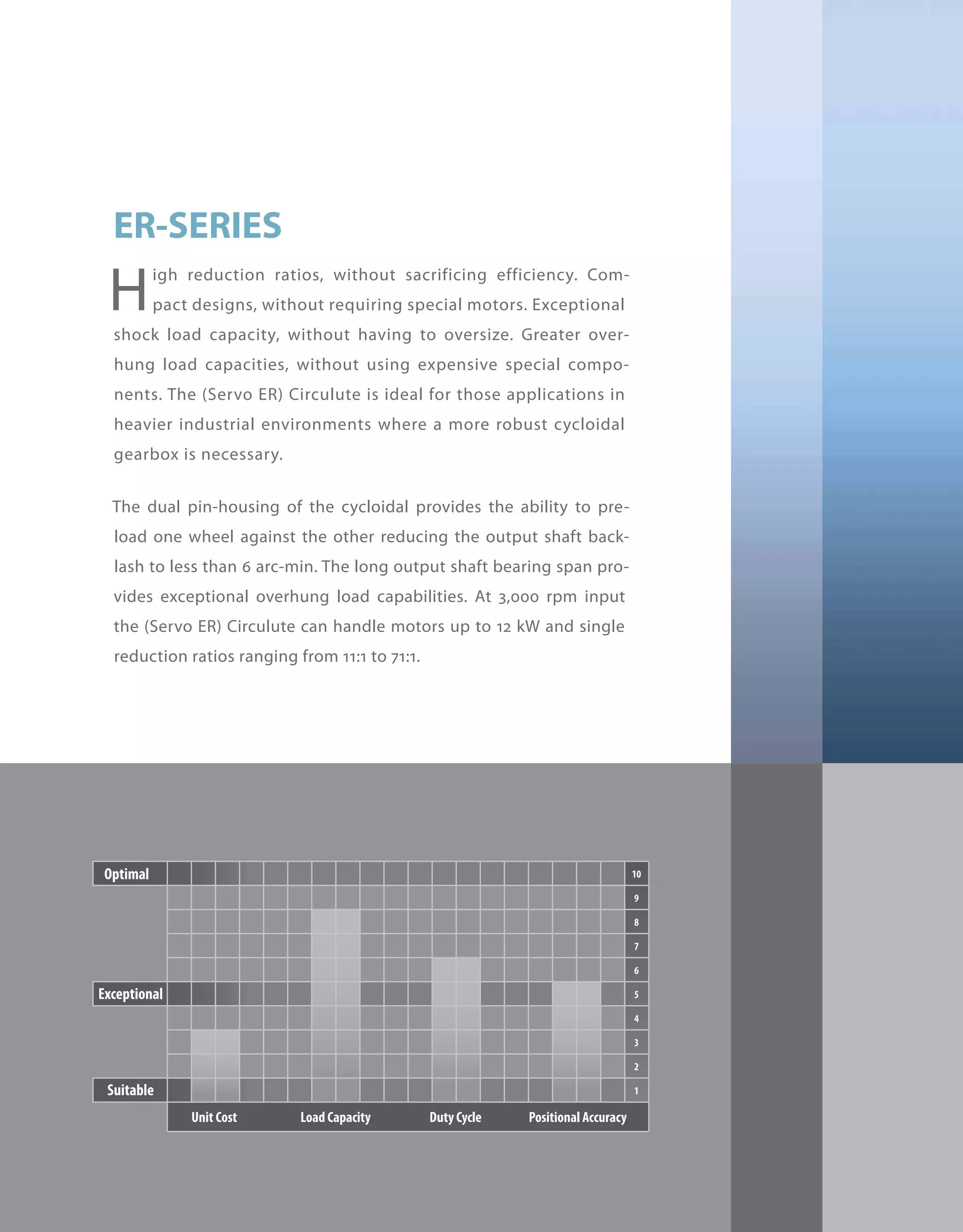


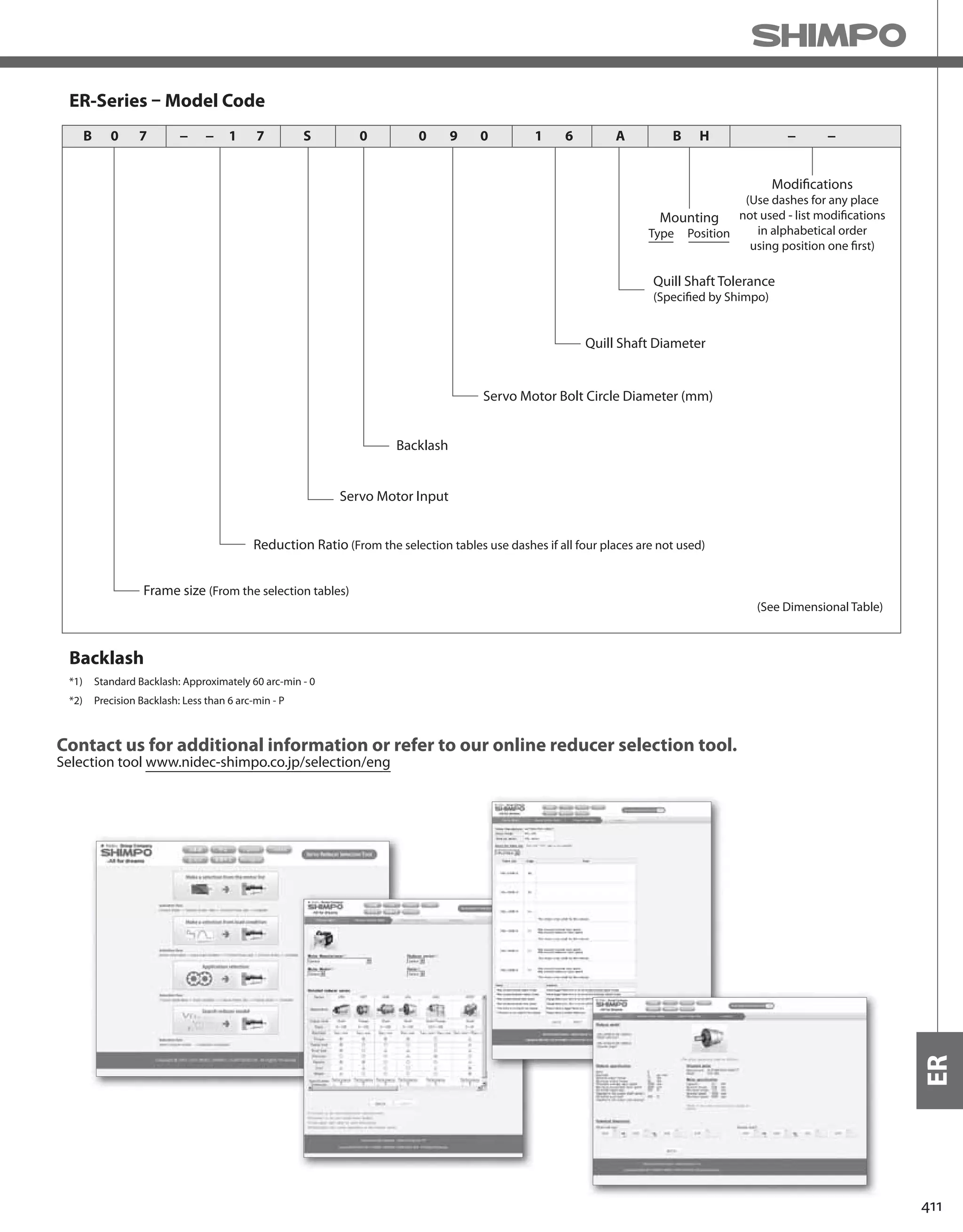
![412
ER-SERIES Circulute 3000 cycloidal reducer
Rating Table - 3000 rpm Input, Single Reduction, Precision Backlash (less than 6 arc-min)
*1) The reducer can continuously sustain this torque value without overheating
*2) The reducer can sustain this torque value for 1000 cycles without failure
*3) Acceleration torque is 1.5 times the nominal output torque
Frame Size Ratio Units Notes 11 17 29 35 47 59 71
B03
Input [kW] -- 1.430 1.160 0.710 0.560 0.390 0.320 0.250
Nominal Output Torque [Nm] *1 45.000 56.300 59.200 56.600 52.800 54.000 51.400
Emergency Stopping Torque [Nm] *2 112 141 148 141 132 135 128
Torsional Rigidity [Nm/arc-min] -- 3.000 4.700 5.000 5.400 5.400 5.400 5.400
Moment of Inertia [kg-cm2] -- 0.716 0.969 0.927 0.927 0.927 0.927 0.927
B07
Input [kW] -- 1.900 1.540 0.950 0.750 0.520 0.430 0.340
Nominal Output Torque [Nm] *1 60.000 75.000 78.900 75.400 78.200 79.900 76.100
Emergency Stopping Torque [Nm] *2 150 188 197 189 196 200 190
Torsional Rigidity [Nm/arc-min] -- 3.000 4.700 5.000 5.400 5.400 5.400 5.400
Moment of Inertia [kg-cm2] -- 0.716 0.969 0.927 0.927 0.927 0.927 0.927
C03
Input [kW] -- 2.910 2.690 1.690 1.550 1.080 0.860 0.710
Nominal Output Torque [Nm] *1 91.700 131 140 155 145 145 144
Emergency Stopping Torque [Nm] *2 229 328 350 388 362 362 361
Torsional Rigidity [Nm/arc-min] -- 6.200 11.200 11.900 12.600 12.600 12.600 12.600
Moment of Inertia [kg-cm2] -- 3.118 3.412 4.171 4.129 4.086 4.086 4.086
C07
Input [kW] -- 3.880 3.590 2.250 2.060 1.430 1.140 0.950
Nominal Output Torque [Nm] *1 122 175 187 207 214 214 214
Emergency Stopping Torque [Nm] *2 306 437 467 517 536 536 535
Torsional Rigidity [Nm/arc-min] -- 6.200 11.200 11.900 12.600 12.600 12.600 12.600
Moment of Inertia [kg-cm2] -- 3.118 3.412 4.171 4.129 4.086 4.086 4.086
D03
Input [kW] -- 6.830 5.380 3.400 3.010 2.240 1.720 1.360
Nominal Output Torque [Nm] *1 215 262 282 302 302 290 277
Emergency Stopping Torque [Nm] *2 538 654 705 754 754 725 693
Torsional Rigidity [Nm/arc-min] -- 17.800 23.000 25.200 27.400 27.400 27.400 27.400
Moment of Inertia [kg-cm2] -- 7.752 10.996 12.007 11.754 11.754 11.754 11.501
D07
Input [kW] -- 9.110 7.170 4.530 4.010 2.990 2.290 1.820
Nominal Output Torque [Nm] *1 287 349 376 402 447 430 411
Emergency Stopping Torque [Nm] *2 718 872 940 1,010 1,120 1,070 1,030
Torsional Rigidity [Nm/arc-min] -- 17.800 23.000 25.200 27.400 27.400 27.400 27.400
Moment of Inertia [kg-cm2] -- 7.752 10.996 12.007 11.754 11.754 11.754 11.501](https://image.slidesharecdn.com/shimpohighprecisioncatalog-140807090507-phpapp01/75/Shimpo-high-precision-catalog-414-2048.jpg)
![413
ER
Rating Table - 2000 rpm Input, Single Reduction, Precision Backlash (less than 6 arc-min)
*1) The reducer can continuously sustain this torque value without overheating
*2) The reducer can sustain this torque value for 1000 cycles without failure
*3) Acceleration torque is 1.5 times the nominal output torque
Frame Size Ratio Units Notes 11 17 29 35 47 59 71
E03
Input [kW] -- 13.100 11.600 9.710 8.050 5.390 4.430 3.420
Nominal Output Torque [Nm] *1 618 849 1,210 1,210 1,090 1,120 1,040
Emergency Stopping Torque [Nm] *2 1,540 2,120 3,030 3,030 2,730 2,800 2,600
Torsional Rigidity [Nm/arc-min] -- 54.800 70.400 85.200 85.200 85.200 85.200 85.200
Moment of Inertia [kg-cm2] -- 31.512 52.661 49.291 48.869 48.448 48.448 48.027
E07
Input [kW] -- 17.400 15.500 13.000 10.700 7.190 5.910 4.570
Nominal Output Torque [Nm] *1 824 1,130 1,610 1,610 1,450 1,500 1,390
Emergency Stopping Torque [Nm] *2 2,060 2,660 3,520 3,520 3,520 3,520 3,480
Torsional Rigidity [Nm/arc-min] -- 54.800 70.400 85.200 85.200 85.200 85.200 85.200
Moment of Inertia [kg-cm2] -- 31.512 52.661 49.291 48.869 48.448 48.448 48.027
F03
Input [kW] -- 20.200 19.900 17.000 14.800 10.800 8.170 6.790
Nominal Output Torque [Nm] *1 953 1,450 2,120 2,230 2,180 2,070 2,070
Emergency Stopping Torque [Nm] *2 2,380 3,630 5,300 5,580 5,450 5,180 5,180
Torsional Rigidity [Nm/arc-min] -- 116.700 122.300 133.400 133.400 133.400 133.400 133.400
Moment of Inertia [kg-cm2] -- 87.628 74.989 130.178 127.650 127.650 127.650 125.122
F07
Input [kW] -- 26.900 26.500 22.600 19.800 14.400 10.900 9.060
Nominal Output Torque [Nm] *1 1,270 1,940 2,820 2,970 2,900 2,760 2,760
Emergency Stopping Torque [Nm] *2 3,180 4,850 7,050 7,350 7,350 6,900 6,900
Torsional Rigidity [Nm/arc-min] -- 116.700 122.300 133.400 133.400 133.400 133.400 133.400
Moment of Inertia [kg-cm2] -- 87.628 74.989 130.178 127.650 127.650 127.650 125.122](https://image.slidesharecdn.com/shimpohighprecisioncatalog-140807090507-phpapp01/75/Shimpo-high-precision-catalog-415-2048.jpg)
![414
ER-SERIES Circulute 3000 cycloidal reducer
ER Common Dimensions – Single Stage Base Mount
*1) Sizes A through B do not have a lifting eye
T
L
Key
U
R
V
BA
F1
F
ØDF
Motor
Mounting
Flange
B
4-H
E
A
D
G
P
W
Frame Size Units A B BA D DF E F F1 G H P
A03 - A07 [mm] 175.01 119.89 65.28 89.99 N/A 145.03 89.92 14.99 16.00 11.94 147.07
A190 - A195 [mm] 180.09 134.87 59.94 100.00 N/A 150.11 89.92 14.99 11.94 10.92 147.07
B01 - B07 [mm] 175.01 150.11 85.85 115.01 N/A 145.03 119.89 14.99 16.00 11.94 150.11
B195 - B105 [mm] 180.09 134.87 59.94 100.00 N/A 150.11 89.92 14.99 11.94 10.92 150.11
B20H [mm] 180.09 134.87 59.94 119.99 N/A 150.11 89.92 14.99 11.94 10.92 150.11
C01 - C07 [mm] 219.96 189.99 103.38 140.00 N/A 180.09 150.11 20.07 22.10 14.99 189.99
C110 - C115 [mm] 230.12 154.94 82.04 119.99 N/A 189.99 115.06 20.07 14.99 13.97 189.99
C225 [mm] 230.12 154.94 82.04 140.00 N/A 189.99 115.06 20.07 14.99 13.97 189.99
D01 - D07 [mm] 275.08 230.12 135.38 165.00 N/A 225.04 180.09 24.89 25.91 19.05 234.95
D135 [mm] 330.20 195.07 100.08 149.99 N/A 290.07 145.03 24.89 22.10 18.03 234.95
D145 [mm] 330.20 195.07 119.89 149.99 N/A 290.07 145.03 24.89 22.10 18.03 234.95
D225 [mm] 330.20 195.07 119.89 159.99 N/A 290.07 145.03 24.89 22.10 18.03 233.68
E01 - E07 [mm] 359.92 299.97 150.88 184.99 312.93 299.97 249.94 24.89 29.97 22.10 299.97
E165 [mm] 409.96 238.00 138.94 159.99 312.93 369.82 150.11 43.94 24.89 18.03 299.97
E370 - E375 [mm] 430.02 335.03 124.97 200.00 312.93 379.98 275.08 29.97 29.97 22.10 414.02
F03 - F07 [mm] 424.94 365.00 194.82 210.01 368.05 350.01 294.89 35.05 35.05 24.89 359.92](https://image.slidesharecdn.com/shimpohighprecisioncatalog-140807090507-phpapp01/75/Shimpo-high-precision-catalog-416-2048.jpg)
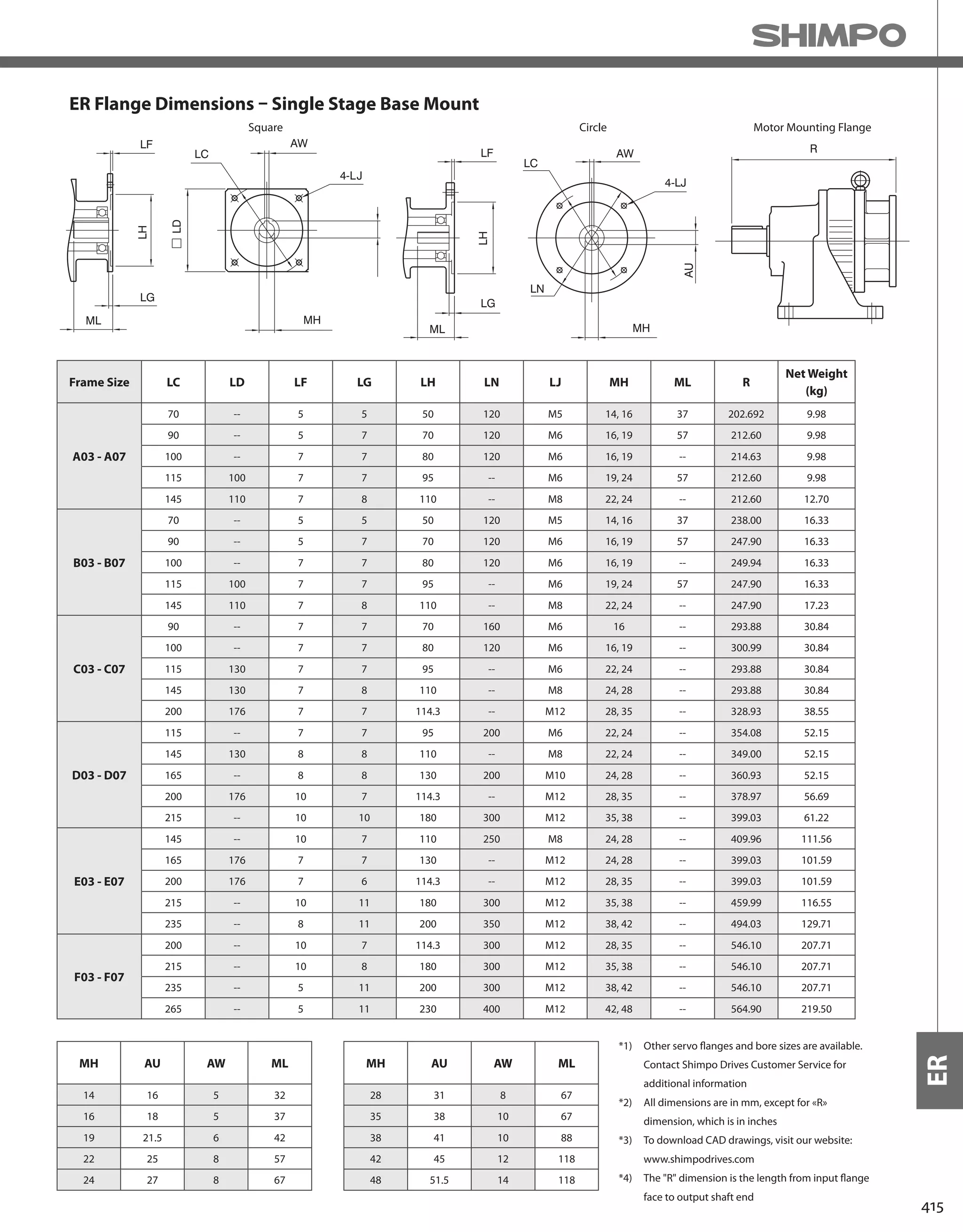
![416
ER-SERIES Circulute 3000 cycloidal reducer
ER Common Dimensions – Single Stage Flange Mount
HO
AG
C
BDØ
R
BBBE
AMØ
AG
L
T
U
UA
Key
Key
BH
V
VA
DFØ
Motor
Mounting
Flange
Shaft
Input
Sizes D01-F07
Sizes A03-C07
BF Hole Diameter
BG Number of Holes
BF Hole Diameter
BG Number of Holes
Output Flange
Output Shaft
Input Shaft
Frame Size Units AG AM BB BD BE BF BG BH HO
A03 - A07 [mm] 130.05 110.01 4.06 160.02 13.97 11.94 101.60 29.97 N/A
B01 - B07 [mm] 165.10 130.00 4.06 199.90 13.97 11.94 101.60 40.13 N/A
C01 - C07 [mm] 214.88 180.01 4.06 249.94 18.03 14.99 101.60 55.12 N/A
D01 - D07 [mm] 264.92 230.00 5.08 299.97 22.10 14.99 203.20 70.10 184.91
E01 - E07 [mm] 350.01 300.00 7.87 400.05 24.89 19.05 203.20 89.92 230.12
F03 - F07 [mm] 400.05 350.01 7.87 450.09 24.89 19.05 203.20 109.98 260.10
Frame Size Units
Output Shaft
U V Key T L
A03 - A07 [mm] 22.23 30.23 4.78x4.78x24.89 N/A N/A
B01 - B07 [mm] 34.925 50.80 7.95x7.95x44.96 N/A N/A
C01 - C07 [mm] 44.450 63.50 9.53x9.53x54.86 N/A N/A
D01 - D07 [mm] 63.500 95.25 15.88x15.88x74.93 M10 x 1.5 18.03
E01 - E07 [mm] 73.025 111.00 19.05x19.05x95.00 M20 x 2.5 35.05
F03 - F07 [mm] 92.075 139.70 22.23x22.23x115.06 M20 x 2.5 35.05](https://image.slidesharecdn.com/shimpohighprecisioncatalog-140807090507-phpapp01/75/Shimpo-high-precision-catalog-418-2048.jpg)


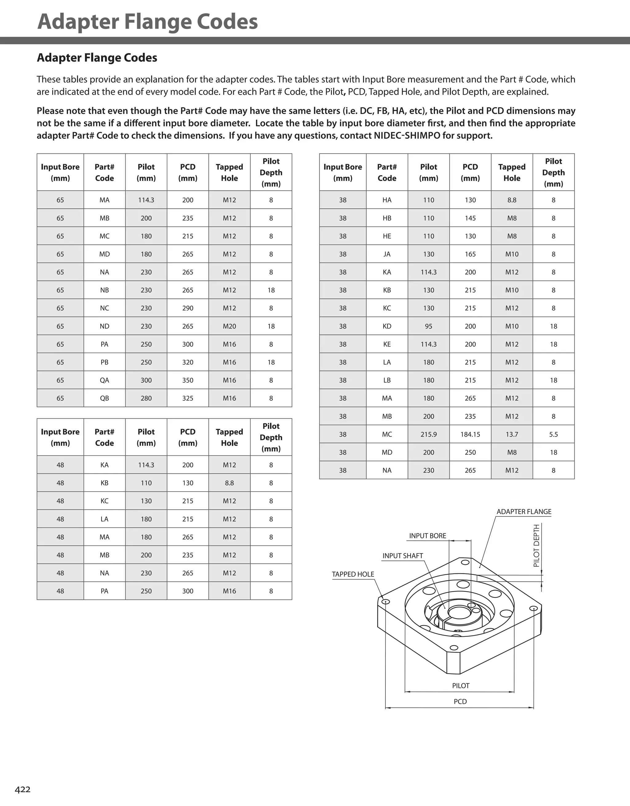

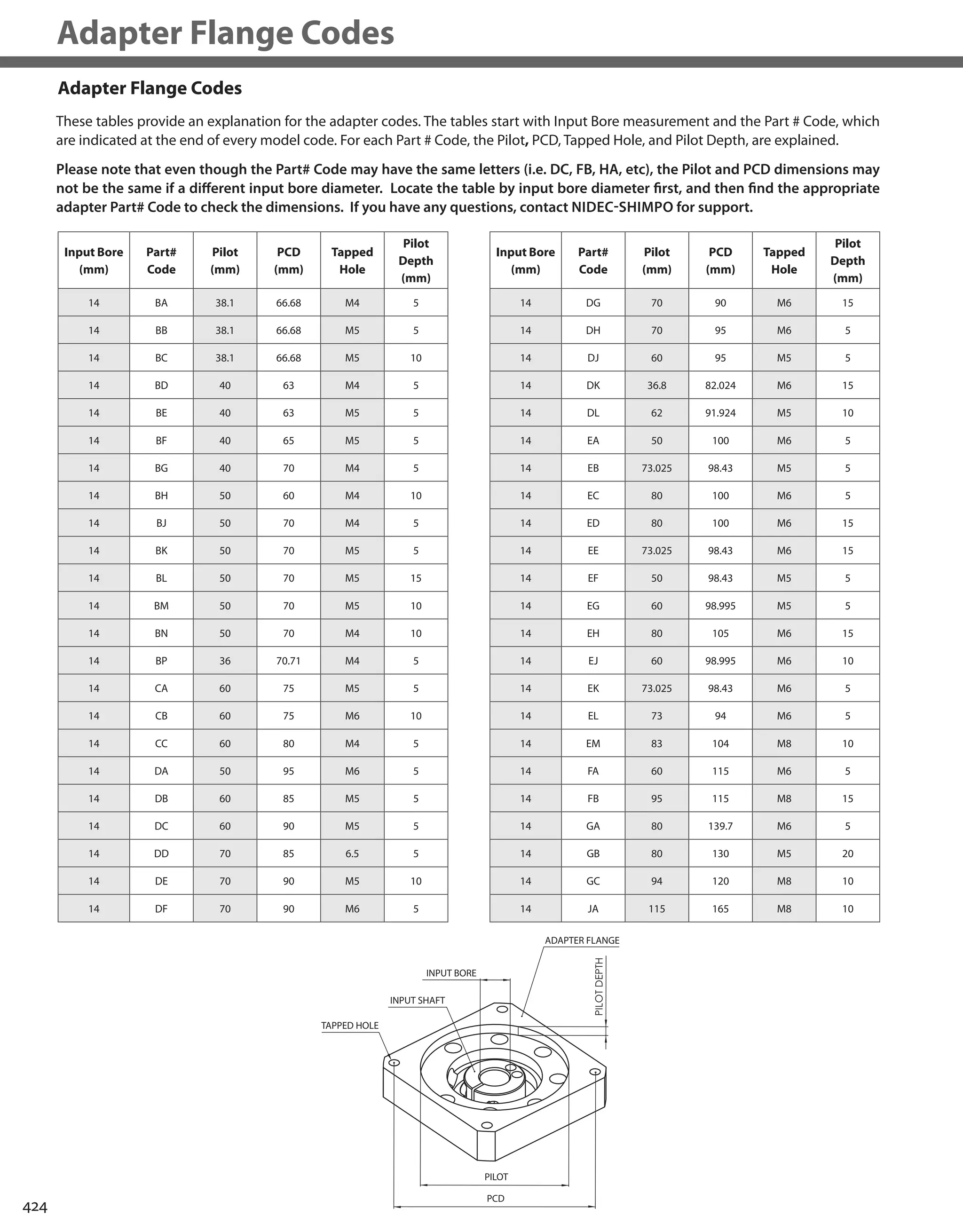
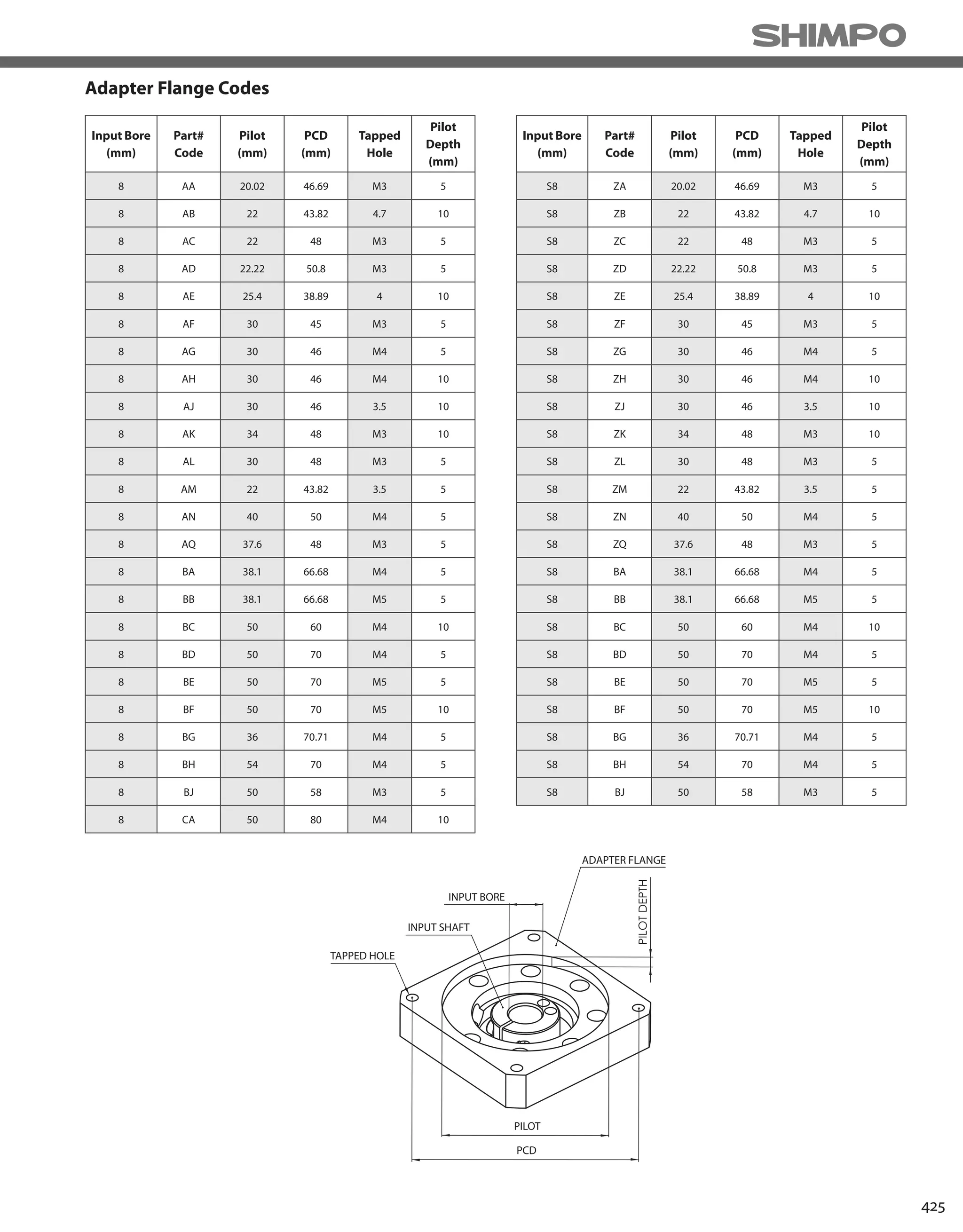
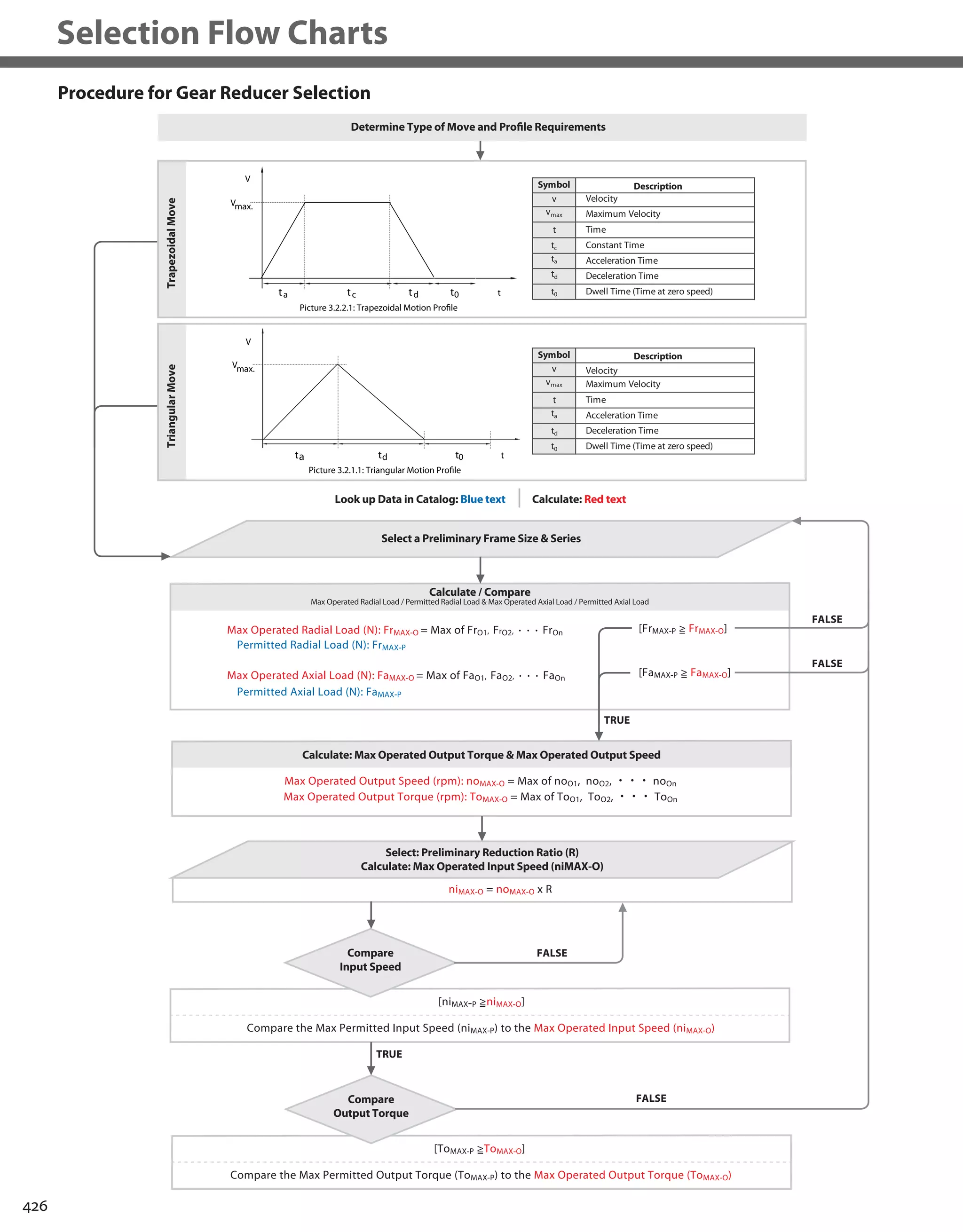


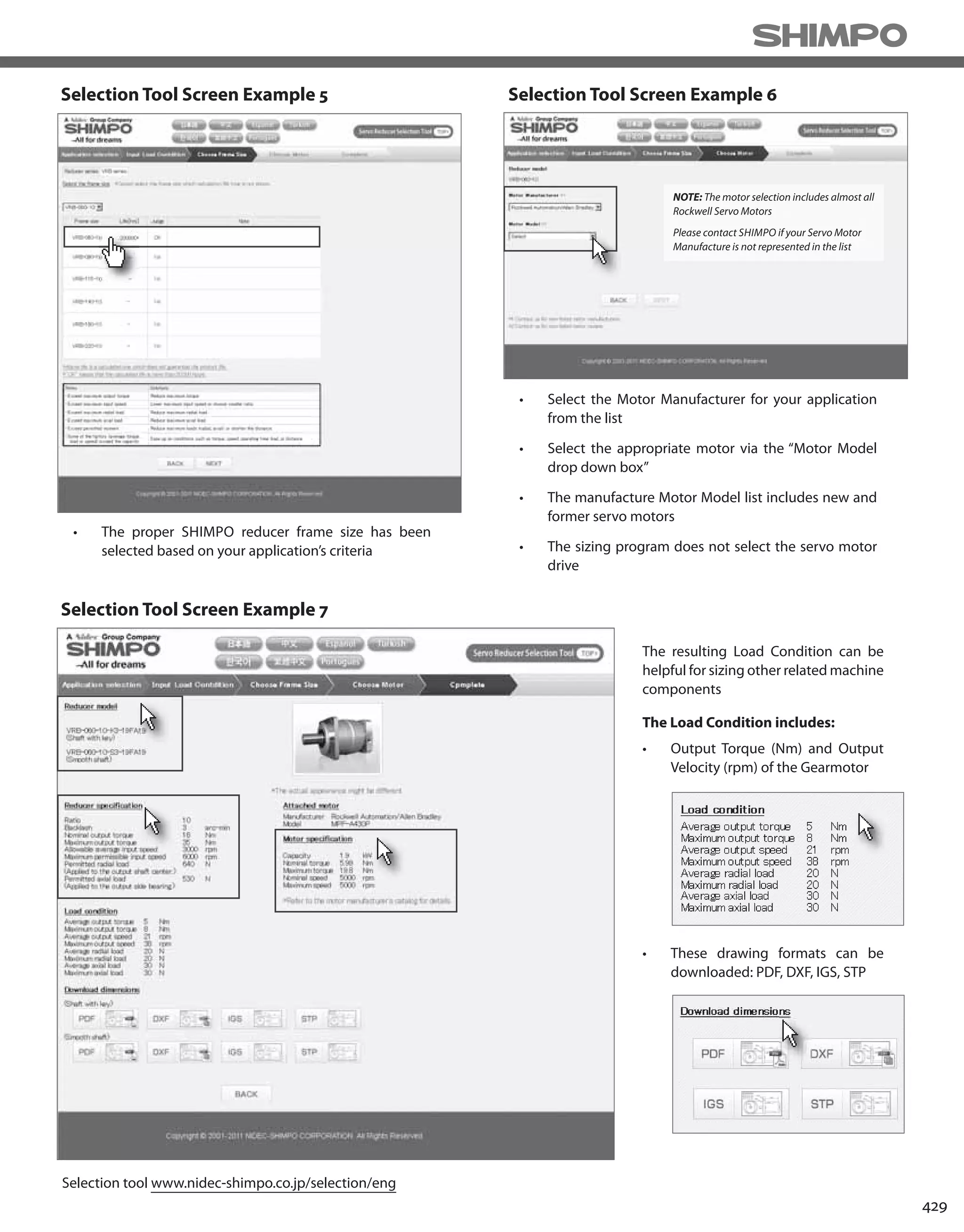


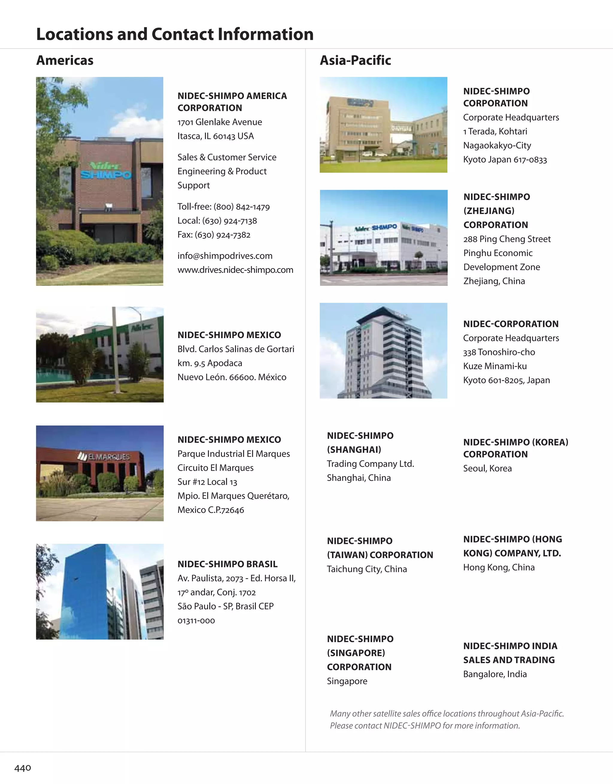


This document is a catalog from NIDEC-SHIMPO, a manufacturer of precision power transmission products and subsidiary of NIDEC Corporation. It summarizes NIDEC-SHIMPO's history and product lines. Originally founded in 1952 in Kyoto, Japan, NIDEC-SHIMPO has expanded globally and developed a wide range of high precision speed reducers, gearboxes, and actuators. The catalog provides an overview of the company and its parent NIDEC Corporation, as well as detailed specifications for its full product portfolio.


![Vibe Coding vs. Spec-Driven Development [Free Meetup]](https://cdn.slidesharecdn.com/ss_thumbnails/vibecodingvsspecdrivendevelopment-251209105622-43f455e7-thumbnail.jpg?width=640&height=640&fit=bounds)


