Low Rate Call Girls Pune Esha 9907093804 Short 1500 Night 6000 Best call girl...
Chapter 5 gyroscope
1. Chapter 5 Gyroscope
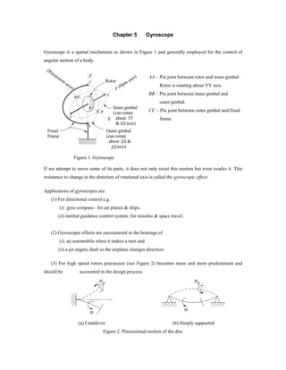
Gyroscope is a spatial mechanism as shown in Figure 1 and generally employed for the control of
angular motion of a body.
Rotor
Inner gimbal
(can rotate
about
& axis)
YY
XX
Outer gimbal
(can rotate
about &
axis)
XX
ZZ
Y
Fixed
Frame
X
Z
(Spin axis)
(Precession axis)
A
B
C
A
B
C
Figure 1. Gyroscope
AA – Pin joint between rotor and inner gimbal.
Rotor is rotating about YY axis.
BB – Pin joint between inner gimbal and
outer gimbal.
CC – Pin joint between outer gimbal and fixed
frame.
If we attempt to move some of its parts, it does not only resist this motion but even evades it. This
resistance to change in the direction of rotational axis is called the gyroscopic effect.
Applications of gyroscopes are:
(1) For directional control e.g.
(i) gyro compass : for air planes & ships.
(ii) inertial guidance control system: for missiles & space travel.
(2) Gyroscopic effects are encountered in the bearings of
(i). an automobile when it makes a turn and
(ii) a jet engine shaft as the airplane changes direction.
(3) For high speed rotors precession (see Figure 2) becomes more and more predominant and
should be accounted in the design process.
p p
(a) Cantilever (b) Simply supported
Figure 2. Precessional motion of the disc
2. 93
Gyroscopic Couple:
It can be easily studied using the principle of angular momentum. Angular velocity is a vector
quantity. Change in magnitude and direction of angular velocity results in angular acceleration: Let in
Figure 3, OA and OB are in x-z plane, θ∆ is the angular displacement of OA and OC is the angular
displacement vector. Similarly angular velocity, angular acceleration and angular momentum are also
vector quantity.
Y
X
Z
O
B
A
C ,
Figure 3. Angular displacement vector
Linear momentum: It is defined as
Linear momentum = mass × velocity = mv (1)
The direction and sense of the linear momentum are same as linear velocity.
m v
Figure 4. A particle in motion (Linear momentum)
Angular momentum: It is defined as the moment of linear momentum.
Angular momentum ( ) ( ) ωω ImrrmvH ==== 2
(2)
where I is the mass of inertia about it’s axis of rotation and ω is the angular velocity.
m v= r
r
axis of rotation
k =
(a) A point mass in rotation
k
v
Mass is con-
centraded at
radius of
gyration
(b) A flywheel in roatation
Figure 5. Angular momentum
3. 94
Direction of angular momentum will be same as angular velocity.
2
H mvk m kk mk Iω ω ω= = = = where 2
mkI = (3)
The gyroscopic couple is given as spIC ωω= , where spωω is the acceleration components. The
direction of torque vector will be along the spin vector on rotating spin vector by 900
in the direction
of precession vector (as shown in Figure 6).
s
C
90
0
p
(spin vector)
(precession vector)
(torque vector)
Figure 6. Gyroscopic Torque
To cause precession of a spinning body, an external torque must be applied to the body (rotor) in a
plane normal to the plane in which the spin axis is precessing. Our objective is to determine the
required external torque to produce precession motion as specified or vice versa.
Gyroscopic action on aeroplane structure: Let C be the couple on the rotor by the plane or external
couple the – C will be the reaction of the plane on the rotor.
R
p
s
s
p
C
- C
900
(active couple
on the rotor)
(reactive couple
on the plane)
The action of the
plane will be such
that it will try to
fall the nose
}External couple should
be acting on rotor from
the bearing support
Figure 7. Motion of an aeroplane Figure 8. Gyroscopic couple on the aeroplane
4. 95
Exercise: The rotor of a turbojet engine has a mass 200 kg and a radius of gyration 25 cm. The engine
rotates at a speed of 10,000 rpm in the clockwise direction if viewed from the front of the aeroplane.
The plane while flying at 1000 km/hr. turns with a radius of 2 km to the right. Compute the
gyroscopic moment the rotor exerts on the plane structure. Also, determine whether the nose of the
plane tends to rise or fall when the plane turns.
(Note: Here due to reaction couple of gyroscopic effect aeroplane will pitch about transverse axis
which in turn give rise to a gyroscopic couple which will try to rotate the aeroplane in opposite to the
direction of rotation. The rate of change of angular momentum α
ω
I
dt
d
I
dt
dH
== . By Newton’s
Law: == T
dt
dH
Torque to produce the angular acceleration, hence αIT = ).
• A rotor mounted on two bearings: A rotor is spinning with constant angular velocity sω , the
angular momentum is given by sIH ω= . Let S-P-G are rectangular coordinate system (see
Figure 9).
F
-F
S B
H
d
O
F
-F
B
C
G
P
D H'
2
1
p
s
s
p
C
Center of mass &
center of rotation
External
force from
bearing
s
H
= I
F . d = C
C
C
Figure 9. A rotor mounted on two bearings
5. 96
OS is the spin axis, OP is the precession axis, OG is the gyroscopic torque axis and F is the action
force on the shaft so that (–F) is the reaction force on bearings. Let the shaft (or spin axis) presses
through an angle θ∆ about P axis. Angular momentum will change from H to H ′, i.e.
HHH ∆+=′
where H∆ is the change in angular momentum (due to change in direction of H). From OCD∆
( )( )θ∆= OCCD or ( )θ∆=∆ HH or θω ∆=∆ sIH
Rate of change of angular momentum,
0
lim
→∆
=
tdt
dH
pss ItI ωωθω =∆∆ / where pω is the uniform
angular velocity of precession, hence
psIC ωω= (5)
where C is the gyroscopic couple. The gyroscopic couple will have same sense and direction as
H∆ i.e. .OC From right hand screw rule we will get the direction of torque i.e. clockwise about axis
OG when seen from above. This is active couple acting on the disc. Whenever an axis of rotation or
spin axis changes its direction a gyroscopic couple will act about the third axis. A reactive gyroscopic
couple will be experienced by bearings through the shaft.
Alternative deviation of gyroscopic couple
Z Z
Z Z
Y
Y
Y
Y
X X
O P
y z
2 y ps
s
2 y ps
P'
P
r
z
s
y
s
s
p
s
r
2 y ps
2 yp
s
P'
P
z=0
s
zs
C
90
o
p
2 ys p
X
X
p
p
O
O
s y
P'
P
Plan view(top view)
P
p
Figure 10. Gyroscopic couple on a rotating disc.
6. 97
Let XX id the spin axis ( )sω and YY is the precession axis ( )pω . Particle P has coordinates ( )θ,r
and mass of dm. The velocity .OPrs ⊥ω Velocity component in: ZZ direction = θω sinrs = ysω
and in the YY direction = θω cosrs = zsω . Particle P is having motion along the z axis (or || to z-
axis). Simultaneously, it is rotating about axis Y-Y. So a Corriolis component of acceleration =
ps yωω2 acts ⊥ to plane of paper and outwards as shown in the side view (Figure 10). Similarly for
particle ,P′ the Corriolis acceleration component will be ps yωω2 and it acts ⊥ to plane of paper and
inwards as shown in the side view (Figure 10). The accelerating forces arising out of these Corriolis
acceleration components, produce a couple C about ZZ-axis.
Force due to acceleration of the particle ps ydmP ωω2=
Moment about ZZ-axis 2
2 s pdm yω ω= , hence total moment about ZZ-axis
2
2 2s p s p zzC y dm Iω ω ω ω= =∫ ( )2 1/ 2s p Iω ω=
where ( )2
1/ 2zzI y dm I= =∫ , where I is the polar moment of inertia (for thin disc).C acts along the
ZZ-axis towards right. Moment about YY-axis = ps zydm ωω2 , hence
Total moment about YY-axis = ∫ = zypsps Izydm ωωωω 22 where ∫ == 0zydmIzy
Also there is no Corriolis component of acceleration when we analyze the motion of particle in y-
direction since 0=zzω . If disc is not symmetric then 0≠zyI , so we will get yyzz CC & both.
s
p
C (active couple on
the disc)
Same as the
direction of
change of angular
momentum of disc
Figure11. Free body diagram of the disc
P
z
= 0z
s
7. 98
F
F
-C
(reaction
forces on the
shaft from
bearings)
(reaction on
the shaft)
-F
-F
(reaction forces
from the shaft ends
to the foundation
or frame.)
Thin rod rotating about its centroidal axis
In Figure 12, we have XX as the axis of spin and YY as the axis of precession. Due to Corriolis
component of acceleration the force at point P, of the mass dm is given as
( )θωω sin2 rdmdF sp= (1)
which is ⊥ to plane of the paper as shown in side view (Figure 12). Moment of this force about BB
axis
( )θωω sin2 2
rdmdFrdC spBB == (2)
A
AP
y
z
B
B
C
r
P
x x
dF'
dF
s
p
BB
Figure 12. Thin rod rotating about its centroid axis.
Total moment of all particle above and below the BB axis is given as
( ) 2 2
2 2 sin 2 sinBB p s p s p s BBC r dm r dm Iω ω ω ω θ ω ω θ= = =∫ ∫ (3)
where ∫= dmrIBB
2
(4)
From parallel axis theorem, we have: BB AAI I I= + . Since 0≈AAI for thin rod, we have
8. 99
BBAABB IIII ≈+= (5)
Equation (5) reduces to
2 sinBB s pC Iω ω θ= (6)
which is ⊥ BB, as shown in Figure 12 and can be obtained by right hand rule. Taking component of
couple BBC about yy and zz axis:
θωω 2
sin2 pszz IT = ( )θωω 2cos1−= psI (7)
and
θθωω cossin2 psyy IT = θωω 2sinpsI= (8)
There are two gyroscopic couples respectively about zz-axis and yy-axis. This comes because of
asymmetric body of revolution. BB AAI I≠ . zzT and yyT are varying with θ , i.e. zzT varies from 0 to
psI ωω2 and yyT varies from psI ωω− to psI ωω . The above analysis is applicable to two bladed
propeller or airscrew (Figure 13).
B
B
Figure 13. Two bladed propeller Figure 14. Three bladed propeller
The above analysis can be extended to a multi-bladed airscrew. Let n be the number of blades
( 3≥n ), n/2πα = is equally spaced angle between two blades.
pszz IC ωω= and 0=yyC
where 1nII = , 1I is the mass moment of inertia of each blade about an axis BB. Let the moment of
inertia of each blade about axis BB (i.e. ⊥ to blade) be equal to BBI which in turn is equal to 1I ,
( )1 BB AA BBI I I I= + ≈ . Total moment of inertia of the airscrew about the axis of rotation is: 1nII = .
Let us consider one of the blades, which is inclined to an angle θ with zz-axis.
9. 100
Y
Y
Z Z
Figure15. One of the blade position
Total moment about zz-axis
( )2 2
1 1 12 2 sin 1 cos2z s p s p s pC y dm I Iω ω ω ω θ ω ω θ= = = −∫ (9)
Location of other blades is given by phase angle ( )α1−n . Summing up the moments due to all n
blades, we have
[ ] ( )[ ]αθωωθωω +−+−= 2cos12cos1 11 pspszz IIT
( )[ ] ( ){ }[ ]αθωωαθωω 12cos1...22cos1 11 −+−+++−+ nII psps
( ) ( ) ( ){ }{ }[ ]αθαθαθθωω 12cos...22cos2cos2cos1 −+++++++−= nnI ps
which can be simplified as
( ){ }[ ]αααθωω sin/sin2/12cos1 nnnIT pszz −+−=
Since n/2πα =
For 2>n , 0sin ≠α check for ,3/2π ...4/2π
0sin =α πα 2=n
For all values of 2>n , pszz nIT ωω1= or pszz II ωω= (10)
αα sin/sin n becomes ( )n/2sin/2sin ππ , hence for
1=n , sin 2 /sin 2 1π π =
2=n , sin 2 /sin 0/ 0 0π π = →
3=n , ( )sin2 / sin 2 / 0/finite 0nπ π = →
4=n , etc. 0→
10. 101
Hence,
( )θωω 2cos11 −= pszz IT for ,2=n 0sin =α , 0sin =αn
Moment about YY-axis for a blade, which makes angle θ with ZZ-axis is:
1 sin 2yy s pT I ω ω θ=
Total moment about YY for n blades is (phase angle ( )α1−n )
( ) ( )( ){ }1 sin2 sin 2 ... sin 2 1yy s pT I nω ω θ θ α θ α = + + + + + −
(11)
0yyT = for 2n >
The sine series will be zero for all values .2>n So with equations (10) and (11), we can conclude
that for multi bladed screw with number of blades 3 and above is equivalent to a plane disc with polar
mass moment of inertia nII = about axis of rotation.
Gyroscopic Stabilization
Gyroscopes can be used for the stabilization of ships, aeroplanes etc. The motion can be termed as
follows: Steering or yawing about vertical axis, pitching about transverse axis, and rotating about
longitudinal axis. Generally rolling is more as compared to pitching or yawing. So gyroscope can be
applied to reduce rolling. The basic purpose of gyroscope is to reduce the amplitude of the oscillations
of the ship in a sea.
Steering
or
Yawing
Star board
Pitching
Transverse
axis
Longitudinal
axis
Bow (Free end)Rolling
Stern
(Rear end)
Port
Figure 16. Ship-motions
Basic principle of stabilization of gyroscope:
The gyroscope shall be made to precess in such a way that the reaction couple exerted by the rotor
(i.e. – C) shall oppose any disturbing couple (i.e. CW external couple or applied couple to rotor)
11. 102
which may act on the frame (of gyroscope), because of the waves of seas. If at every instant the
reaction couple of the gyroscope (i.e. – C) and the applied or disturbing couple (CW) are equal, then
complete stabilization will be obtained. Due to change in slope of the wave and due to the buoyancy
effect the ship will experience a couple. Generally waves are periodic (or sinusoidal). So ship will
experience sinusoidal external couple in rolling. In order to maintain the ship stable, an equal and
opposite reaction couple must be applied by the gyroscope.
Vertical longitudianal
plane
Horizontal plane
Transverse plane
Figure 17. A ship in a rough sea
In rolling, external couple is in transverse plane. So reaction couple from gyroscope should also act in
same plane. (i.e. along longitudinal axis). So choice is there to choose spin axis either in the vertical
or in transverse direction and accordingly for precession axis). This depends upon practical constraint.
Precession is given to gyroscope manually (just like steering wheel). And it has to be given
continuously. (or by variable speed motor with reversing direction capability). In Figure 18, we have
WC is the external couple applied by wave, oa I s the angular momentum, WC is the ⊥ to plane
of paper inward, and H∆ is the Horizontal towards left. So precession should be such that it should
produce a reaction couple, ,C− (i.e. same as magnitude and opposite to the direction or sense of the
external couple, C) or gyroscope should experience an applied couple equal to, ( )WCC = , such that
reaction couple, ,C− will counterbalance external couple, C. The external couple from wave will be
in the same plane (i.e. C vector will be ⊥ to the plane of paper). But reaction couple, ,C− will
change its direction (i.e. from ⊥ to the plane of paper as it precess due to pω ). So only component of
reaction couple, ,C− will be available to counteract external couple, C, of wave. Also slope of the
wave θ is also changing continuously. So WC component will be maximum for maximum slope &
zero when slope is zero.
12. 103
C
a o
b
H
T cosr
Tr
s p
W
p
C
900
o
b a
Hp
CW
s
s
p0
90
Figure 18(a). Spin is axis along the longitudinal
direction (Due to pitching no change of spin axis.
So no gyroscopic action will be there. Yawning
motion is rare. So this orientation is preferred).
Figure 18(b). Spin axis is along the vertical
direction (Due to pitch change in spin axis. So
gyroscopic action will be there).
C - C CW
Active
gyroscopic
couple
Reactive
couple
Applied
couple by
wave
Figure 19. Gyroscopic couple direction is ship
If WCT =φsin is disturbing couple applied by the wave, where φ is the slope of the wave (see
Figure 17). So, for 0=φ , 0=WC and for =φ maximum, maxsinφTCW = . CTr −= is the
gyroscopic reaction couple that is applied by the gyroscope on the ship for an inclination of the plane
of rotation by θ to the horizontal, then
φθ sincos TTr = or φθωω sincos TI ps =
13. 104
When, maxφφ = , then 0=θ and when 0=φ , then, 0
90θ → (impractical) end of quarter period
( )4/t of the wave. Therefore, we can reduce the amplitude of rolling if not fully prevent it. Reference
: The Automatic Stabilization of Ships, By T.W. Chalmers.
Stability of a four-wheel drive vehicle moving on a curved path
Left turn
G
h
x
W I I W
I WW I
GC
F
- C
W/W/
1, 21 1
113, 4,
,
44
p
c
p
s
C
- C
(action on rotors
i.e. wheel & engine)
(reaction on
vehicle body)
Beacuse rotors
are fixed to the
frame of the
vehicle body
90
0
Figure 20.
Reaction at wheels:
(i) Due to weight, 4/mg where m is the mass of the wheel
(ii) Due to centrifugal force RmvFc /2
= , where v is the velocity of vehicle, R is the radius
of the curved path, and m is the mass of vehicle. On taking moment balance on the transverse
plane of the vehicle, we have UxhFc = where U is the reaction at the inner and outer wheels
(having two wheels at each of the inner and outer sides) due to the centrifugal force. Hence, on
each wheel the reaction force due to centrifugal force will be xhFU c /2/ = . Now total reaction
2/4/ UW −= at inner wheel and at outer wheel 2/4/ UW +=
14. 105
(iii) Gyroscopic action due to four wheels: 4w w s pT I ω ω= , where wI is the moment of inertia of
each wheel and /p V Rω = . The torque due to the engine, peee IT ωω= . Total torque is given by
eg TTT ±= ω , where + sign when eω and sω are having same sense and – sign when eω and
sω are having opposite sense. We have gTVx = which gives xTV g /= , where V is the
reaction at the inner and outer wheels due to the gyroscopic couple.
Total reaction at each of inner wheel
/ 4 / 2 / 2innerT W U V= − −
and outer wheel
/ 4 / 2 / 2outerT W U V= + +
At high speed or in the sharp turn, innerT may become zero, so for the stability of the vehicle,
0innerT > or ( )/ 4 /2W U V> +
Example 1: A trolley can with a total mass of 2700 kg runs on rail 1 m apart with a speed of 30-km/
hr. The track is curved with a radius of 40 m towards the rigid of the driver. The car has four wheels
each of diameter 70 cm and the total moment of inertia of each pair of wheels and the axle is 15 kg-
m2
. The car is driven by a motor running in the direction opposite to that of the wheels at a speed five
times the speed of rotation of the wheels .The motor and the gear pinion have a moment of inertia 10
kg m2
. The rails are at the same level and the height of the center of gravity of the car is 1 m above the
rail level. Determine the vertical force exerted by each wheel on the rails.
Solution: V
d
Figure 21 Trolley in a curved path
15. 106
2700 kg; 1 ; 0.7 m; 1 m; 30 / 8.33 / ; 0.2083 rad/s.t w p
V
m d m d h V km hv m s ω
R
= = = = = = = =
wω
V
wω′
Figure 22 A wheel of the trolley
I12
; ;w w w wV ω r ω ω V πdω′ ′= ≠ =
For wheels: ; 3.79 rad/s.w w wπd ω V ω= =
For engine: 5 18095 rad/s = 3.79 rad/s.E wω ω= =
Gyroscopic couple: ( ) [2 15 3.79 10 18.95] 0.2083 15.79 Nm.ω w E E pC I ω I ω ω= − = × × − × × = −
So the effect of net gyroscopic couple will to that outer wheel reactions will decrease (since direction
of net gyroscopic couple is in the direction of EC′ ) and increase the reactions at inner wheels. Let due
to gyroscopic effect the reaction at inner wheel is 2G. On taking moment about an axis passing
through outer wheel we get.
2 distance betwen traks or 2 1 (-15.79) 0
or 7.895 N So 7.895 N and G0 -7.895 N
i i
i i
G C G
G G
× = × + =
= = =
Due to weight: Force on each wheel 6621.75 N
4
mg
w = =
Due to centrifugal force: Taking moment about the outer track, we have
0
2
2
1 (2 ) 1 0; 1 (2 ) 1 0
1
or -2343.75 N and 2343.75 N
i i
i
C C C
C C
mv
F F F
F F
× + × = ∴ × + × =
= = +
Vertical reactions at each of the outer wheel 6621.75 7.895 2343.75 8997.6= − + = N
On each of the inner wheel: 6621.75 7.895 2343.75 4285.9 N= + − = .
Example 2: The wheels of a motorcycle have a moment on inertia 68 kg m2
and engine parts a
moment of inertia of 3.4 kgm2
. The axis of rotation of the engine crankshaft is parallel to that of the
road wheels. If the gear ratio is 5 to 1, the diameter of the road wheels is 65 cm and the motor cycle
16. 107
rounds a curve of 30.5 m radius at 60 km/hour, find the magnitude and direction of the gyroscopic
couple.
Solution:
2 2
68 kgm ; 3.4 kgm ; Gear ratio 5:1; 65 , 30.5
Velocity 60 km/hr 16.67 m/sec
wheel Engine wheelI I n D cm R m= = = = = =
= =
2 2 2 2
16.67 16.67
0.5464 /sec and 51.28 /sec.
30.5 0.65 2
68 51.28 0.5464 1905.31 /sec and 3.4 256.41 0.5464 476.34 /sec
motorcycle wheel
wheel axle engine
ω rad ω rad
C kgm C kgm
= = = =
= × × = = × × =
Note: 2
1425.52 kgmC =
C (Reactive) )active(engineC
pω pω
wheelω engineω
C (active)
(Re ctive)engineC a−
Relative couple direction is on the fame of the frame of the motorcycle either from wheel axle or from
engine seat.
Exercise Problems:
1. The rotor o a Jet airplane engine is supported by two bearings as shown in Figure1. The rotor
assembly including compressor, turbine, and shaft is 6672 N in weight and has a radius of gyration of
229 mm. Determine the maximum bearing force as the airplane undergoes a pullout on a 1830 m
radius curve at constant airplane speed of 966 km/h and an engine rotor speed of 10,000 rpm. Include
the effect of centrifugal force due to the pullout as well as the gyroscopic effect.
--------------------------************************--------------------------