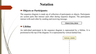
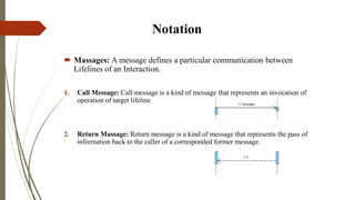
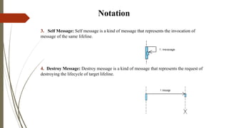
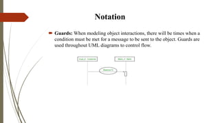
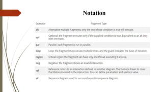
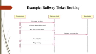
Presentation On
Sequence And State Flow Diagram
Presented by
1. Rambhakta Pandey(818)
2. Amit Thakur
3.Pawan Regmi
4.Prashant Kunwar
Presented to
Er.Nirajan Hamal
lecturer,
Himalayan Whitehouse International
College
Presentation Outline
 What is Sequence Diagram?
 Purpose of Sequence Diagram
 Notation
 Example
 Conclusion
What is Sequence Diagram?
 Sequence diagram simply depicts interaction between objects in a
sequential order.
 These are also called as “Event Diagram”.
Purpose of Sequence Diagram
1. Model high-level interaction between active objects in a system.
2. Model the interaction between object instances within a collaboration
that realizes a use case.
3. Model the interaction between objects within a collaboration that
realizes an operation.
Notation
 Objects or Participants:
The sequence diagram is made up of collection of participants or objects. Participants
are system parts that interact each other during sequence diagram. The participants
interact with each other by sending and receiving message.
 Lifeline
An individual participant in the sequence diagram is represented by a lifeline. It is
positioned at the top of the diagram. It is represented by vertical dashed line.
Notation
 Activation or Execution Occurrence:
It is represented by a thin rectangle on the lifeline. It describes that time period in
which an operation is performed by an element, such that the top and the bottom of
the rectangle is associated with the initiation and the completion time, each
respectively.
Notation
 Massages: A message defines a particular communication between
Lifelines of an Interaction.
1. Call Message: Call message is a kind of message that represents an invocation of
operation of target lifeline.
2. Return Massage: Return message is a kind of message that represents the pass of
information back to the caller of a corresponded former message.
Notation
3. Self Message: Self message is a kind of message that represents the invocation of
message of the same lifeline.
4. Destroy Message: Destroy message is a kind of message that represents the request of
destroying the lifecycle of target lifeline.
Notation
 Guards: When modeling object interactions, there will be times when a
condition must be met for a message to be sent to the object. Guards are
used throughout UML diagrams to control flow.
Notation
Example: Railway Ticket Booking
Conclusion
 a good diagram to use to document a system’s requirements and to
flush out a system’s design.
 it shows the interaction logic between the objects in the system in
the time order that the interactions take place.
presentation on sequence and state flow diagram

presentation on sequence and state flow diagram

  • 1.
    Presentation On Sequence AndState Flow Diagram Presented by 1. Rambhakta Pandey(818) 2. Amit Thakur 3.Pawan Regmi 4.Prashant Kunwar Presented to Er.Nirajan Hamal lecturer, Himalayan Whitehouse International College
  • 2.
    Presentation Outline  Whatis Sequence Diagram?  Purpose of Sequence Diagram  Notation  Example  Conclusion
  • 3.
    What is SequenceDiagram?  Sequence diagram simply depicts interaction between objects in a sequential order.  These are also called as “Event Diagram”.
  • 4.
    Purpose of SequenceDiagram 1. Model high-level interaction between active objects in a system. 2. Model the interaction between object instances within a collaboration that realizes a use case. 3. Model the interaction between objects within a collaboration that realizes an operation.
  • 5.
    Notation  Objects orParticipants: The sequence diagram is made up of collection of participants or objects. Participants are system parts that interact each other during sequence diagram. The participants interact with each other by sending and receiving message.  Lifeline An individual participant in the sequence diagram is represented by a lifeline. It is positioned at the top of the diagram. It is represented by vertical dashed line.
  • 6.
    Notation  Activation orExecution Occurrence: It is represented by a thin rectangle on the lifeline. It describes that time period in which an operation is performed by an element, such that the top and the bottom of the rectangle is associated with the initiation and the completion time, each respectively.
  • 7.
    Notation  Massages: Amessage defines a particular communication between Lifelines of an Interaction. 1. Call Message: Call message is a kind of message that represents an invocation of operation of target lifeline. 2. Return Massage: Return message is a kind of message that represents the pass of information back to the caller of a corresponded former message.
  • 8.
    Notation 3. Self Message:Self message is a kind of message that represents the invocation of message of the same lifeline. 4. Destroy Message: Destroy message is a kind of message that represents the request of destroying the lifecycle of target lifeline.
  • 9.
    Notation  Guards: Whenmodeling object interactions, there will be times when a condition must be met for a message to be sent to the object. Guards are used throughout UML diagrams to control flow.
  • 10.
  • 11.
  • 12.
    Conclusion  a gooddiagram to use to document a system’s requirements and to flush out a system’s design.  it shows the interaction logic between the objects in the system in the time order that the interactions take place.