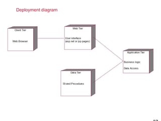
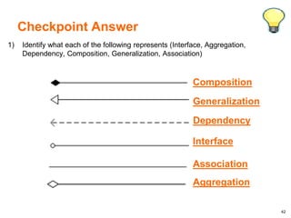
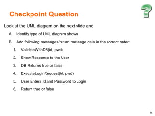
Here is the class diagram for the given scenario:
«interface»
Moveable
+move()
Mammal
-numOfLegs : int
+getNumOfLegs() : int
+setNumOfLegs(int numOfLegs) : void
+eat() : void
Lion
+roar() : String
Dog
-age : int
+getAge() : int
+setAge(int age) : void
+woof() : String
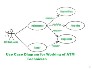
1
1..*
Jungle
+area() : double
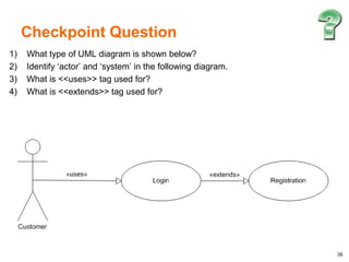
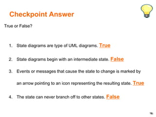
Checkpoint Answer
�45
1) Draw a sequence diagram for the following scenario:
A customer
![18
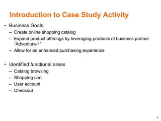
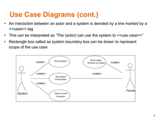
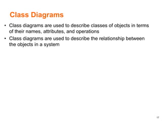
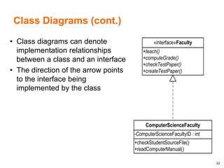
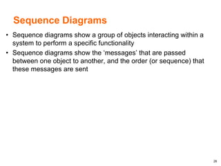
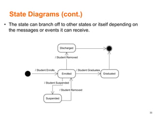
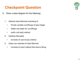
Class Diagrams (cont.)
• A Class diagram is composed of a
class icon that defines the class itself
• The class icon describes the name of
the class, the attributes of a class, and
the behaviors/operations of a class
+enrollSubject()
+dropSubject()
+getCurrentSchedule()
-Name : String
-BirthDate : Date
-Grade : Integer
-Subjects[] : Subject
Student](https://image.slidesharecdn.com/uml-240412131318-b948c32d/85/UML-Design-Document-Training-Learn-UML-pptx-18-320.jpg)
![21
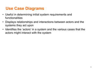
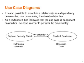
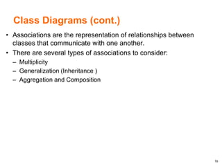
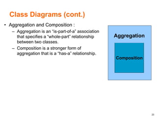
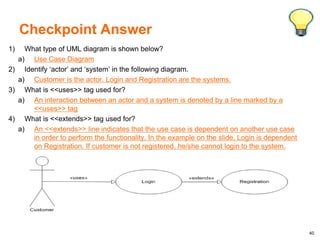
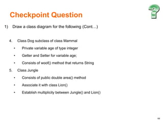
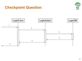
Class Diagrams (cont.)
• Class diagrams can denote inheritance
relationships between two classes
• The direction of the arrow points to the
base or the parent class
+enrollSubject()
+dropSubject()
+getCurrentSchedule()
-Name : String
-BirthDate : Date
-Grade : Integer
-Subjects[] : Subject
Student
+getRequiredSubjects()
-Minimum GPA : Double
-Required Subjects[] : Subject
Honor Student](https://image.slidesharecdn.com/uml-240412131318-b948c32d/85/UML-Design-Document-Training-Learn-UML-pptx-21-320.jpg)
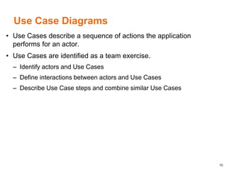
![24
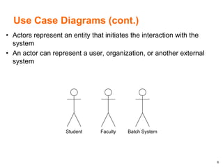
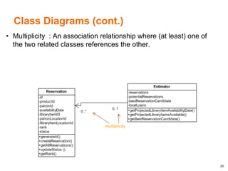
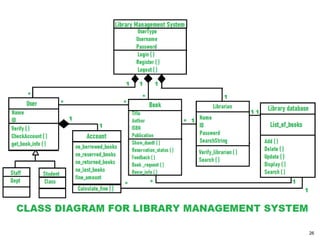
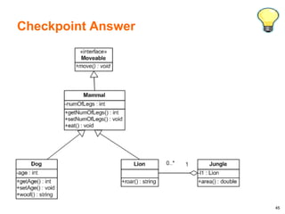
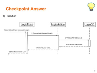
Class Diagrams (cont.)
• Class diagrams can be used to show a ‘strong’ aggregation
between two objects
• It is denoted as a ‘has-a’ relationship between the two objects
• The lifetime of the object that is contained is dependent on the
lifetime of the container object
+enrollSubject()
+dropSubject()
+getCurrentSchedule()
-Name : String
-BirthDate : Date
-Grade : Integer
-Subjects[] : Subject
-StudentHistory[] : Student History
Student
+retrieveNotes()
+retrievePreviousGPA()
+retrieveCompletedSubjects()
-Subject
-Grade
-School
-Note
-Year
Student History
1 0..*](https://image.slidesharecdn.com/uml-240412131318-b948c32d/85/UML-Design-Document-Training-Learn-UML-pptx-24-320.jpg)
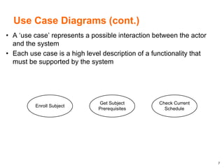
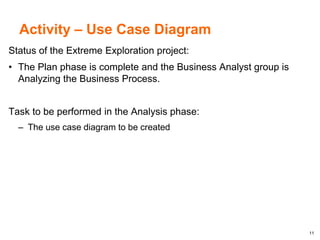
![25
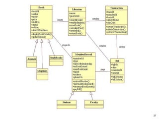
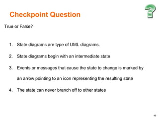
Class Diagrams (cont.)
• An ‘association’ relationship can be formed denoting a ‘weak’
aggregation between two objects
• In an association relationship, the objects can exist
independently of each other
+enrollSubject()
+dropSubject()
+getCurrentSchedule()
-Name : String
-BirthDate : Date
-Grade : Integer
-Subjects[] : Subject
-StudentHistory[] : Student History
Student
-Name : String
-Description : String
-Prequisites[] : Subject
Subject
1 0..*](https://image.slidesharecdn.com/uml-240412131318-b948c32d/85/UML-Design-Document-Training-Learn-UML-pptx-25-320.jpg)
![29
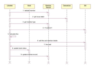
Sequence Diagrams (cont.)
• Messages are indicated as solid horizontal arrows attached to
the timeline of the source object to the target object
• Dashed horizontal arrows indicate the response of the message
receiver
Student Scheduler UI Scheduler DB
retrieve available subjects
retrieveSubjectList()
return Subject[]
display Subjects[]](https://image.slidesharecdn.com/uml-240412131318-b948c32d/85/UML-Design-Document-Training-Learn-UML-pptx-29-320.jpg)


![谷歌留痕技术教程[ 𝙩𝙤𝙥 𝟮𝟯𝟯. 𝙘 𝙤𝙢 ]](https://cdn.slidesharecdn.com/ss_thumbnails/top233-260130173900-2eb784f9-thumbnail.jpg?width=640&height=640&fit=bounds)


![20260201 [FOSDEM] gomodjail - library sandboxing for Go modules.pdf](https://cdn.slidesharecdn.com/ss_thumbnails/20260201fosdemgomodjail-librarysandboxingforgomodules-260201225659-76609ec4-thumbnail.jpg?width=640&height=640&fit=bounds)


