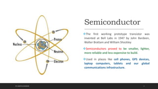
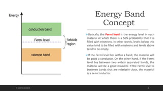
The document discusses semiconductor diodes and their history. It explains that semiconductors like silicon proved to be smaller, lighter, and more reliable replacements for vacuum tubes in electronics. The document then covers key topics like silicon crystals, energy band concepts, doping to create N-type and P-type semiconductors, PN junctions, biasing of diodes, and breakdown mechanisms. Specific diode types like LEDs and photodiodes are also summarized.
This document provides an overview of basic electronics components and circuits. It begins with an introduction to passive components like resistors, capacitors, inductors, and transformers. It then covers analog circuits using transistors and operational amplifiers. The document provides details on circuit analysis and different types of filters. It explains concepts like resistors, capacitors, inductors, diodes, transistors, and operational amplifiers. Examples of common circuits are also presented like voltage dividers, rectifiers, and amplifiers.
This document describes 11 different types of diodes: Zener diode, varactor diode, light-emitting diode (LED), photodiode, laser diode, Schottky diode, PIN diode, tunnel diode, small signal diode, large signal diode, and Shockley diode. It provides details on each diode type, including its basic structure and functions, symbol, and common applications. The document also includes separate sections focused on describing the key characteristics and uses of LEDs, photodiodes, and laser diodes.
This document discusses the Schottky diode, a semiconductor diode with a low forward voltage drop and very fast switching speeds. It forms a metal-semiconductor junction, using a metal like molybdenum or platinum in contact with an N-type semiconductor like silicon. This creates a Schottky barrier and results in fast switching without the charge storage and recovery time of a conventional PN junction diode. Key advantages are voltage drops as low as 0.15V, no reverse recovery time, and operation at frequencies from MHz to GHz. Applications include rectification, switching, and protection circuits.
This document discusses semiconductor diodes and rectifiers. It begins by explaining the physical principles of semiconductors, including intrinsic semiconductors and how doping with materials like phosphorus or boron creates n-type and p-type semiconductors. When a p-type and n-type material meet, it forms a pn junction with interesting electrical properties. Diodes are made from pn junctions and exhibit asymmetric conduction, allowing current in one direction but blocking it in the other. Diode circuits and models are also covered, along with important applications like rectification where diodes are used to convert AC to DC power.
An electric circuit is a connection of electronic components like voltage/current sources, resistors, inductors and capacitors. Power is supplied by a source and dissipated by another component. The purpose of electronic components is to control current flow to achieve a specified output. Resistors restrict current flow while capacitors can store energy and diodes allow current to flow in one direction. Transistors are commonly used for amplification and switching. Integrated circuits combine multiple components on a single chip to perform complex functions.
This presentation gives a lot of information about
Semiconductor Devices.This is presented by Rajesh Kumar Sangani from Rajiv Gandhi University of Knowledge Technologies,Basar Dist
Adilabad,A.P,India.
This ppt is about semiconductor diodes.You can get every basic information about PN junction diode and its working and some more information about the semiconductors.
Differential amplifiers amplify the difference between two input signals while rejecting input signals that are common to both inputs. They have advantages like excellent stability, versatility, and immunity to noise and interference. The differential gain (Ad) is the gain with which the difference between the two input signals (V1-V2) is amplified to produce the output (Vo). The common mode gain (Ac) is the gain resulting from any common signals applied to both inputs. Differential amplifiers have high differential gain, low common mode gain, and high common mode rejection ratio (CMRR), which is the ratio of Ad/Ac expressed in decibels and indicates the ability to reject common mode signals.
Tunnel diodes are heavily doped PN junction diodes that exhibit negative resistance. They were invented in 1958 by Dr. Leo Esaki and operate based on the quantum mechanical principle of tunneling. When forward biased, the current initially increases with voltage but then decreases as the voltage is further increased, demonstrating the unique property of negative resistance. Tunnel diodes find application in ultrafast switching, memory storage, satellite communication equipment, and oscillators due to their negative resistance characteristic.
The document discusses the hybrid or h-parameters model of bipolar junction transistors. It provides notations and equations for the key h-parameters, including input impedance (h11), forward current gain (h21), reverse voltage transfer ratio (h12), and output admittance (h22). It also describes how to calculate the h-parameters from transistor static characteristics and the advantages of the h-parameter model for circuit analysis and design.
A bipolar junction transistor (BJT) consists of two PN junctions formed by sandwiching either a p-type or n-type semiconductor between two opposite types. It has three sections - the emitter, base, and collector. Current flows due to both electrons and holes, making it a bipolar device. The base is lightly doped and very thin to allow charge carriers to easily move from the emitter to the collector. BJTs can be used as amplifiers because the collector current is controlled by the base current.
A diode is a two-terminal electronic component that allows current to flow in only one direction. It is used to convert alternating current to direct current through a process called rectification. Diodes come in various types including laser diodes, light emitting diodes, Zener diodes, and silicon diodes. Rectification uses diodes to convert AC to DC through either half-wave or full-wave rectification circuits. Zener diodes are used in the reverse bias mode as voltage regulators. Photodiodes generate current or voltage when illuminated by light and are used in applications like machine vision, range finding, and medical diagnostics.
Electronic device and circuit presentationKamrulHasan506
This presentation discusses the importance of electronic device knowledge in computer science education. It begins by introducing electronic devices like transistors and diodes that are used to control electrical currents for information processing and system control. It then explains how modern electronic devices like smartphones use semiconductors because they can be made to conduct electricity sometimes and not other times. The heart of electronic devices are semiconductors, which are made more conductive through doping. Semiconductors allow computers to perform calculations using many transistor switches on small silicon chips. Electronic devices are crucial to computer systems, memory, data storage, signaling, and digital technologies that power modern computing.
The phototransistor is a light sensor formed from a basic transistor with a transparent cover. It has higher sensitivity than a photodiode. Phototransistors use the transistor effect to amplify the current generated by light, providing gain. They can use homojunction or heterojunction structures and operate in either linear or switch modes depending on the circuit configuration and load resistor value. Common emitter and common collector circuits are widely used.
This article discusses different power electronics devices that are in use like power diodes, power thyristors, power transistors, IGBT, GTO, IGCT and others. This article will give a basic view of these devices and their operations.
This presentation is for beginners of electronics. This will give you a brief about all the important basic building blocks of electronics and hence will be helpful in creating a good foundation.
Varactor diode is a type of PN junction diode where the capacitance of the PN junction can be controlled by applying a reverse bias voltage. As the reverse bias voltage is changed, the width of the depletion region between the P and N semiconductors changes, altering the capacitance. Varactor diodes are commonly used in applications like variable resonant tank circuits, automatic frequency control circuits, and frequency modulation in radios and televisions. They operate by varying the capacitance through adjustment of the depletion region width, similar to how the distance between capacitor plates controls capacitance.
The document discusses MOSFETs (metal-oxide-semiconductor field-effect transistors). It provides information on:
1) The structure of MOSFETs including typical dimensions of the gate length and width. It operates by using a voltage applied to the gate to control the conductivity between the drain and source.
2) The operation of n-channel and p-channel MOSFETs. In an n-channel MOSFET, applying a positive voltage to the gate creates an n-type inversion channel between the source and drain allowing current to flow.
3) Biasing techniques for MOSFET amplifiers including fixing the gate voltage, connecting a resistor in the source,
There are two main types of transistors: bipolar junction transistors (BJT) and field effect transistors (FET). BJTs use both holes and electrons as current carriers and include NPN and PNP types, while FETs use only one carrier type and include JFETs and MOSFETs. MOSFETs are particularly important as they can be easily integrated into circuits. MOSFETs operate in different modes depending on the voltage applied to the gate and include depletion, enhancement, linear, and saturation modes.
Diodes and its application encapsulate the different characteristics of different type of diodes. Also, define its different biases and how it works.
It provides shortcut method in analyzing Clamper and clipper.
At the end of the powerpoint, there has a review question to answer with answer key provided.
The document discusses CMOS fabrication which involves forming wells and transistors on a silicon substrate through photolithography, etching, and ion implantation processes. NMOS and PMOS transistors are formed by doping different regions with n-type or p-type dopants. Together, these complementary transistors are used to build basic logic gates in integrated circuits with low power consumption. The CMOS process allows for high density, low cost microchips through standard fabrication steps.
When a voltage is applied to a diode, electrons flow from the N-type side through the depletion zone and into the P-type side if the diode is forward biased. This causes current to flow. If the voltage is reversed, the depletion zone widens and no current flows, making the diode act as an open switch. Diodes can be used as rectifiers to convert AC to DC or as switches that allow current in one direction but not the other depending on bias polarity.
The basics of electronics can be watched through the link http://bit.ly/2PPv0mv
A Diode is a semiconductor device with two terminals, typically allowing the flow of current in one direction only.
a thermionic valve having two electrodes (an anode and a cathode).
This document provides information on various electronic components including resistors, capacitors, inductors, connectors, LEDs, IR modules, op-amps, and motor driver ICs. Resistors oppose current flow and have a potential drop. Capacitors store charge and are used for coupling, decoupling, and smoothing circuits. Inductors store energy in magnetic fields. The LM358 op-amp can be used as a comparator to convert analog sensor signals to digital outputs. The H-bridge and L293D motor driver ICs enable controlling motor direction and speed. An IR sensor module uses an IR LED transmitter and photodiode receiver with the LM358 to detect objects based on reflected infrared light.
This document provides an introduction to semiconductor devices and applications. It begins by discussing the basic structure of atoms and how solids can be classified as conductors, insulators, or semiconductors based on their electrical properties. The key concepts of energy bands and band gaps in semiconductors are introduced. The document then covers intrinsic and extrinsic semiconductors, PN junction diodes, their I-V characteristics, and applications such as rectification and voltage regulation using Zener diodes. Switching characteristics of diodes like recovery time are also discussed.
B.Tech sem I Engineering Physics U-II Chapter 1-Band theory of solidAbhi Hirpara
The document discusses band theory of solids and semiconductor devices. It explains that in solids, electrons occupy discrete energy bands separated by forbidden gaps. This leads to the classification of materials as conductors, semiconductors or insulators. Semiconductors can be intrinsic, with equal electron and hole concentrations, or extrinsic through doping. The document describes the operation of simple diodes and Zener diodes, whose sharp breakdown voltage makes them useful for voltage regulation and references.
Electrical current, voltage, resistance, capacitance, and inductance are a few of the basic elements of electronics and radio. Apart from current, voltage, resistance, capacitance, and inductance, there are many other interesting elements to electronic technology. ... Use Electronics Notes to learn electronics online.
This document provides an introduction to analog electronics and discusses key concepts related to semiconductors and diodes. It defines analog electronics as systems with continuously variable signals, as opposed to digital electronics which use discrete signals. Semiconductors are described as having electrical conductivity between conductors and insulators. The document discusses n-type and p-type semiconductors, the PN junction, and diode characteristics under forward and reverse bias. Diode models including the ideal diode model and equivalent circuit models are presented. Key diode parameters such as forward and reverse resistance are also summarized.
B.tech sem i engineering physics u ii chapter 1-band theory of solidRai University
This document provides an overview of band theory of solids. It discusses effective mass of electrons in solids, the concept of holes, and the energy band structure of conductors, semiconductors, and insulators. Intrinsic and extrinsic semiconductors are described, along with p-type and n-type materials. Simple diode and Zener diode operation is summarized, including forward and reverse bias conditions.
Majority and minority charge carriers are defined for p-type and n-type semiconductors. In p-type semiconductors, holes are the majority carriers while electrons are the minority carriers. In n-type semiconductors, electrons are the majority carriers and holes are the minority carriers. Semiconductors are doped with impurities to increase the number of majority carriers, making the material either p-type or n-type. A depletion region forms at the PN junction where majority carriers diffuse across and recombine, leaving an area devoid of carriers.
1. The document discusses band theory and energy bands in solids, explaining that available electron energy states form bands rather than discrete energies as in atoms.
2. Materials are classified as conductors, insulators, or semiconductors based on their band structure, particularly whether the conduction and valence bands overlap or are separated by a band gap.
3. Semiconductors have a small band gap separating the almost-full valence band from the almost-empty conduction band, allowing electrical conductivity to be controlled by doping with impurities. Intrinsic semiconductors contain only the semiconductor material while extrinsic ones are doped with donor or acceptor atoms.
Advancements of Semi conductors and Superconductorsadnanalvi051
explained what are semiconductors and superconductors and their uses. Also nowadays revolutions and advancements in semiconductors as superconductors. After reading these Slides one can easily understand about semiconductors and Superconductors, Nowadays our life is full of semiconductor usage.
This document provides an introduction to semiconductor devices. It discusses band theory and defines key concepts like the valence band, conduction band, and forbidden gap. It explains that semiconductors have a small forbidden gap that electrons can cross with a small amount of energy. Intrinsic and extrinsic semiconductors are introduced, along with p-type and n-type materials which are formed by doping. The document describes how a p-n junction forms a depletion zone and allows current to flow in one direction but not the other. Applications like solar cells, LEDs, and lasers are briefly outlined.
Presentation report for Intrinsic & Extrinsic , N-type & P-type and Forward& ...Obaid ur Rehman
This document is a presentation report on intrinsic and extrinsic semiconductors, n-type and p-type semiconductors, and forward and reverse biasing. It was submitted by 4 students from the University of Lahore's Department of Physics. The 9-page report provides definitions and explanations of these key semiconductor concepts, including a brief history of semiconductors, intrinsic and extrinsic semiconductors, n-type and p-type doping, forward and reverse biasing of p-n junctions, and applications such as LEDs, photodiodes, and solar cells.
Thermionic (vacuum tube) diodes and solid state (semiconductor) diodes were both developed in the early 1900s as radio receiver detectors. Vacuum tube diodes were more commonly used in radios until the 1950s because early semiconductor diodes were less stable. Semiconductor diodes are made from materials like silicon and germanium that have a particular atomic structure making them able to conduct electricity in only one direction, functioning as a diode. The diode's one-way conduction property allows it to be used for rectification of alternating current to direct current among other applications.
This document discusses semiconductor devices and materials. It begins by defining conductors, insulators, and semiconductors based on their conductivity ranges. Intrinsic semiconductors like silicon and germanium have low conductivity that can be increased by temperature. Extrinsic semiconductors are made by doping intrinsics with impurities to add charge carriers. N-type uses donors to add electrons, while P-type uses acceptors to add holes. When a semiconductor is doped with both types, a PN junction is formed with a depletion region and potential barrier. Semiconductor diodes consist of a PN junction that can control current flow. Common applications of semiconductors include transistors in electronics, solar cells,
Electronics and Communication Engineering is the Branch of Engineering. Electronics and Communication Engineering field requires an understanding of core areas including Engineering Graphics, Computer Programming,Electronics Devices and Circuits-I, Network Analysis, Signals and Systems, Communication Systems, Electromagnetics Engineering, Digital Signal Processing, Embedded Systems, Microprocessor and Computer Architecture. Ekeeda offers Online Mechanical Engineering Courses for all the Subjects as per the Syllabus. Visit : https://ekeeda.com/streamdetails/stream/Electronics-and-Communication-Engineering
This document discusses semiconductors and their types. It defines a semiconductor as a material with conductivity between a metal and an insulator. There are two types of semiconductors - intrinsic and extrinsic. Intrinsic semiconductors are pure, while extrinsic are doped with impurities to be either N-type (excess electrons) or P-type (excess holes). The document explains the carrier concentrations and energy band diagrams of the different semiconductor types.
Diploma sem 2 applied science physics-unit 3-chap-1 band theory of solidRai University
This document provides an overview of band theory of solids. It discusses key concepts such as effective mass of electrons, the concept of holes, and the energy band structure of conductors, semiconductors and insulators. It explains that conductors have overlapping valence and conduction bands, semiconductors have a small bandgap, and insulators have a large bandgap. The document also covers intrinsic and extrinsic semiconductors, the operation of p-n junction diodes under reverse and forward bias, and types of diodes such as simple diodes and Zener diodes.
This document provides information on advancements in semiconductors and superconductors. It defines semiconductors and describes their intrinsic and extrinsic types. Applications of semiconductors include displays, RFID tags, and solar cells. Superconductors are materials that conduct electricity without resistance below a critical temperature. The document defines key terms related to superconductors like critical temperature and Meissner effect, and provides examples of superconducting materials like YBa2Cu307.
semiconductor and hall effect.pptx chemistry .....amruthatk3
Semiconductors are materials with an electrical conductivity between conductors and insulators. They have energy bands consisting of a valence band, conduction band, and a forbidden band or bandgap between them. The small bandgap in semiconductors allows electrons to move between bands with small amounts of energy. Semiconductors can be intrinsic, consisting of pure elements like silicon, or extrinsic through doping with impurities. N-type semiconductors are doped with donor atoms that provide extra electrons, while P-type are doped with acceptor atoms that create holes. The document discusses the band structure and carrier concentrations that give semiconductors their unique electronic properties.
This document discusses semiconductors and diodes. It describes how semiconductors have electrical properties between conductors and insulators. Holes and electrons are charge carriers in semiconductors. The band theory of semiconductors involves energy bands and band gaps. Semiconductors have a conduction band and a valence band. Intrinsic semiconductors use a single element, while extrinsic semiconductors are doped with impurities. PN junction diodes are formed from a P-type and N-type semiconductor and have different characteristics under forward, reverse, and zero bias conditions.
1) The document discusses different types of materials used in electronics including conductors, insulators, semiconductors, and their properties. Copper is highlighted as an excellent conductor while insulators have high resistivity.
2) Semiconductors have electrical properties between conductors and insulators. Intrinsic semiconductors are pure while extrinsic are doped with impurities making them either N-type or P-type.
3) A PN junction is formed where a P-type and N-type semiconductor meet, creating a potential barrier. A diode allows current to flow in one direction when forward biased but blocks it in reverse bias.
Similar to Semiconductor Diode: Introduction and Application (20)
This document discusses Ohm's law, which states that the current through a conductor is directly proportional to the voltage applied, provided the physical conditions remain the same. It defines key concepts like voltage, current, and resistance. The three equations of Ohm's law relating voltage, current, and resistance are presented. Applications and limitations of Ohm's law are outlined, and examples of calculating resistance from given voltage and current values are provided. Short answer, multiple choice, and long answer practice questions are included to reinforce understanding of Ohm's law.
The document discusses Industry 4.0, also known as the Fourth Industrial Revolution. It describes the evolution of industries through history from the first industrial revolution in the 1750s to today. Industry 4.0 is defined as using technologies like artificial intelligence and machine learning to connect the physical, digital and biological worlds. It lists some key characteristics of Industry 4.0 as interconnection between machines, information transparency to help decision making, technical assistance for humans, and decentralized decisions by machines. Examples of Industry 4.0 technologies are also provided.
Appropriate technology and entrepreneurship training for students (s atet)Samir Raj Bhandari
Technical Education and Vocational Training(TEVT) plays a vital role in the country’s prosperity and sustainable development. The knowledge, skill, training and attitudes that we acquire paves important foot step for lifelong learning. TEVT helps in shaping the education tomorrow and empowering the youth for future. This proposal is put forward with a vison of providing TEVT for secondary level students for sustainable development of the community
Home automation for prosperity, advancement and sustainable development of th...Samir Raj Bhandari
We are living in the 21st century but still follow traditional methods for entertainment, security, and energy management. Presently we have system that can be easily installed, cost efficient, and able to provide genuine home automation to consumers. We are wasting the energy (more specifically electrical energy) in different fields such as Agriculture, Hospitals, Education, Apartments etc. which can be due to unwanted operation of different loads or equipment
Smart Cities: Self-regulating, Neoteric Or Entrepreneurial ? Samir Raj Bhandari
It implements user-friendly information and communication technologies developed by major industries for urban spaces.
Smart cities are forward-looking, progressive and resource-efficient providing high quality of life. They can be intelligent, progressive, entrepreneurial or all in some cases.
Cyborgs are actually half machine half man and is associated solely with Science fiction and in particular films such as The Terminator, Blade Runner or Minority Report, Iron Man and lot more. In fact, variety of practical cyborg exist and raise moral questions about their impact in the society.
You are humbly requested to fill the questionnaire voluntarily as per your knowledge and understanding. Before the interview can start, the interviewee should sign two copies of this form. The interviewee will be given one copy of the signed form.
Ho-Mation is a proposed home automation startup in Nepal. Its mission is to provide the most customized and reliable automation services. The business model canvas outlines key partners, activities, value propositions, customer relationships, segments, costs, resources, channels, and revenue streams. Ho-Mation aims to address problems with home security and convenience by offering integrated security, entertainment, and energy management hubs. The initial target market is Chitwan, Nepal, with plans for medium and high-income families and offices. Market research on demographics and competitors is presented to support plans for hardware kit sales, maintenance services, and franchise expansion.
Fesiability study of Home Automation in Chitwan Nepal by Ho-Mation Samir Raj Bhandari
This document is a feasibility study for introducing home automation and security products in Chitwan, Nepal. It was prepared by a team of students for an entrepreneurship training program. The study examines the potential market for home automation in Chitwan, outlines proposed products and services, and discusses technology considerations and a marketing strategy. The team aims to design affordable automation solutions that can reduce energy use and provide convenience and security for homes, businesses, and other facilities in Chitwan.
A sample of field visit to a technical institute Nepal Samir Raj Bhandari
Samir Raj Bhandari submitted a report on a field visit to the Butwal Technical Institute (BTI) and Nepal Hydro and Electric Limited (NHE) in Butwal, Nepal. The visit provided students first-hand experience of the practical training and equipment used at BTI and NHE. At BTI, students observed workshops and gained exposure to mechanical, electrical, and welding equipment and training programs. NHE manufactures and maintains hydroelectric power generation and transmission equipment. Students toured NHE's facilities and learned about the turbines, gates, transformers, and other equipment they produce. The field trip offered students valuable practical knowledge to supplement their engineering studies.
Literature Review Basics and Understanding Reference Management.pptxDr Ramhari Poudyal
Three-day training on academic research focuses on analytical tools at United Technical College, supported by the University Grant Commission, Nepal. 24-26 May 2024
Comparative analysis between traditional aquaponics and reconstructed aquapon...bijceesjournal
The aquaponic system of planting is a method that does not require soil usage. It is a method that only needs water, fish, lava rocks (a substitute for soil), and plants. Aquaponic systems are sustainable and environmentally friendly. Its use not only helps to plant in small spaces but also helps reduce artificial chemical use and minimizes excess water use, as aquaponics consumes 90% less water than soil-based gardening. The study applied a descriptive and experimental design to assess and compare conventional and reconstructed aquaponic methods for reproducing tomatoes. The researchers created an observation checklist to determine the significant factors of the study. The study aims to determine the significant difference between traditional aquaponics and reconstructed aquaponics systems propagating tomatoes in terms of height, weight, girth, and number of fruits. The reconstructed aquaponics system’s higher growth yield results in a much more nourished crop than the traditional aquaponics system. It is superior in its number of fruits, height, weight, and girth measurement. Moreover, the reconstructed aquaponics system is proven to eliminate all the hindrances present in the traditional aquaponics system, which are overcrowding of fish, algae growth, pest problems, contaminated water, and dead fish.
Electric vehicle and photovoltaic advanced roles in enhancing the financial p...IJECEIAES
Climate change's impact on the planet forced the United Nations and governments to promote green energies and electric transportation. The deployments of photovoltaic (PV) and electric vehicle (EV) systems gained stronger momentum due to their numerous advantages over fossil fuel types. The advantages go beyond sustainability to reach financial support and stability. The work in this paper introduces the hybrid system between PV and EV to support industrial and commercial plants. This paper covers the theoretical framework of the proposed hybrid system including the required equation to complete the cost analysis when PV and EV are present. In addition, the proposed design diagram which sets the priorities and requirements of the system is presented. The proposed approach allows setup to advance their power stability, especially during power outages. The presented information supports researchers and plant owners to complete the necessary analysis while promoting the deployment of clean energy. The result of a case study that represents a dairy milk farmer supports the theoretical works and highlights its advanced benefits to existing plants. The short return on investment of the proposed approach supports the paper's novelty approach for the sustainable electrical system. In addition, the proposed system allows for an isolated power setup without the need for a transmission line which enhances the safety of the electrical network
International Conference on NLP, Artificial Intelligence, Machine Learning an...gerogepatton
International Conference on NLP, Artificial Intelligence, Machine Learning and Applications (NLAIM 2024) offers a premier global platform for exchanging insights and findings in the theory, methodology, and applications of NLP, Artificial Intelligence, Machine Learning, and their applications. The conference seeks substantial contributions across all key domains of NLP, Artificial Intelligence, Machine Learning, and their practical applications, aiming to foster both theoretical advancements and real-world implementations. With a focus on facilitating collaboration between researchers and practitioners from academia and industry, the conference serves as a nexus for sharing the latest developments in the field.
Using recycled concrete aggregates (RCA) for pavements is crucial to achieving sustainability. Implementing RCA for new pavement can minimize carbon footprint, conserve natural resources, reduce harmful emissions, and lower life cycle costs. Compared to natural aggregate (NA), RCA pavement has fewer comprehensive studies and sustainability assessments.
DEEP LEARNING FOR SMART GRID INTRUSION DETECTION: A HYBRID CNN-LSTM-BASED MODELgerogepatton
As digital technology becomes more deeply embedded in power systems, protecting the communication
networks of Smart Grids (SG) has emerged as a critical concern. Distributed Network Protocol 3 (DNP3)
represents a multi-tiered application layer protocol extensively utilized in Supervisory Control and Data
Acquisition (SCADA)-based smart grids to facilitate real-time data gathering and control functionalities.
Robust Intrusion Detection Systems (IDS) are necessary for early threat detection and mitigation because
of the interconnection of these networks, which makes them vulnerable to a variety of cyberattacks. To
solve this issue, this paper develops a hybrid Deep Learning (DL) model specifically designed for intrusion
detection in smart grids. The proposed approach is a combination of the Convolutional Neural Network
(CNN) and the Long-Short-Term Memory algorithms (LSTM). We employed a recent intrusion detection
dataset (DNP3), which focuses on unauthorized commands and Denial of Service (DoS) cyberattacks, to
train and test our model. The results of our experiments show that our CNN-LSTM method is much better
at finding smart grid intrusions than other deep learning algorithms used for classification. In addition,
our proposed approach improves accuracy, precision, recall, and F1 score, achieving a high detection
accuracy rate of 99.50%.
Presentation of IEEE Slovenia CIS (Computational Intelligence Society) Chapte...University of Maribor
Slides from talk presenting:
Aleš Zamuda: Presentation of IEEE Slovenia CIS (Computational Intelligence Society) Chapter and Networking.
Presentation at IcETRAN 2024 session:
"Inter-Society Networking Panel GRSS/MTT-S/CIS
Panel Session: Promoting Connection and Cooperation"
IEEE Slovenia GRSS
IEEE Serbia and Montenegro MTT-S
IEEE Slovenia CIS
11TH INTERNATIONAL CONFERENCE ON ELECTRICAL, ELECTRONIC AND COMPUTING ENGINEERING
3-6 June 2024, Niš, Serbia
2. General
History After the Industrial Age, the 20th Century
is called the Electronic Age due the
development of electronic vacuum tubes.
Later in the mid 20th Vacuum Tubes were
replaced by Solid State Semiconductor.
Later Diodes and Transistors
2ER. SAMIR RAJ BHANDARI
3. Semiconductor
The first working prototype transistor was
invented at Bell Labs in 1947 by John Bardeen,
Walter Brattain and William Shockley
Semiconductors proved to be smaller, lighter,
more reliable and less expensive to build.
Used in places like cell phones, GPS devices,
laptop computers, tablets and our global
communications infrastructure.
3ER. SAMIR RAJ BHANDARI
4. Silicon as Semiconductor
Material
Silicon, atomic number 14, with an electron shell
configuration of 2-8-4.
The fact that it has a half-filled valence shell with four
electrons puts it in a special place. As is, it's neither a great
conductor nor a superior insulator. With some attention to
detail, it will become a semiconductor.
Silicon is not the only material that can be used for
semiconductors; however it is the most reliable source.
Figure: Bohr model of Silicon.
4ER. SAMIR RAJ BHANDARI
5. Silicon Crystal
All the silicon atoms align in a very specific,
well-ordered manner, without any voids or
breaks in the pattern (mono crystalline
structure)
As silicon has only four electrons in its valence
shell, four more electrons would be needed to
fill the shell.
In the crystal, any given atom of silicon
effectively “shares” an electron from its four
closest neighbors through a covalent bond
Note the color coding that indicates the
sharing.
5ER. SAMIR RAJ BHANDARI
6. Energy Band
Concept
Basically, the Fermi level is the energy level in each
material at which there is a 50% probability that it is
filled with electrons. In other words, levels below this
value tend to be filled with electrons and levels above
tend to be empty.
If the Fermi level lies within a band, the material will
be good a conductor. On the other hand, if the Fermi
level lies between two widely separated bands, the
material will be a good insulator. If the Fermi level is
between bands that are relatively close, the material
is a semiconductor.
6ER. SAMIR RAJ BHANDARI
8. An insulator is a material that does not conduct electrical current or
heat. Insulating materials include paper, plastic, rubber, glass and air.
Semiconductor is a substance, usually a solid chemical element or
compound, that can conduct electricity under some conditions but
not others, making it a good medium for the control of electrical
current.
Its conductance varies depending on the current or voltage applied to a
control electrode, or on the intensity of irradiation by infrared (IR), visible
light, ultraviolet (UV), or X rays.
An electrical conductor is a substance in which electrical charge carriers,
usually electrons, move easily from atom to atom with the application of
voltage. Conductivity, in general, is the capacity to transmit something, such
as electricity or heat.
8ER. SAMIR RAJ BHANDARI
9. Charge Flow in a
Semiconductor
We think of the movement of electrons as a
movement of negative charge, then the movement
of holes can be thought of as a movement of
positive charge.
We can say that the electron is the carrier of
negative charge while the hole is the carrier of
positive charge.
ER. SAMIR RAJ BHANDARI 9
10. Types of Semiconductor
Intrinsic semiconductors: not of particular use as they are neither good conductors nor insulators,
and their conduction is largely dependent on temperature.
We can alter the properties of the material by introducing foreign substances or impurities into the
crystal.
These impurities are also known as dopants. A crystal with an added dopant is referred to as an
extrinsic semiconductor or doped material.
The dopant may be added through a gaseous diffusion process or ion implantation
ER. SAMIR RAJ BHANDARI 10
11. Types of Extrinsic Semiconductor
There are two different types of semiconductors possible.
N-type material:
N-type material is created by adding pentavalent impurities, that is, a dopant with five electrons in
its outer shell. Examples include phosphorus, arsenic and antimony.
P-type material :
P-type material is created by adding a trivalent impurity, one with three electrons in its outer shell.
Possible trivalent impurities include boron, gallium and indium
ER. SAMIR RAJ BHANDARI 11
12. ER. SAMIR RAJ BHANDARI 12
Figure: Doped Crystal and Energy level diagram of N- type material
In N-type material, electrons are the majority charge carrier and holes are the minority charge carrier.
13. ER. SAMIR RAJ BHANDARI 13
Figure: Doped Crystal and Energy level diagram of P- type material
In P-type material,….................. are the majority charge carrier and ….......... are the minority charge carrier.
14. Review Questions
1. Describe the differences between a conductor, an insulator and a semiconductor.
2. Define the terms Fermi level, valence band, conduction band and band gap.
3. What is the fundamental difference between an intrinsic crystal and an extrinsic
crystal?
4. What is meant by the term doping?
5. What is the effect of donor and acceptor impurities on the Fermi level?
ER. SAMIR RAJ BHANDARI 14
17. ER. SAMIR RAJ BHANDARI 17
Assuming the crystal is not at absolute zero,
The thermal energy in the system will cause some of the free electrons in the N material to “fall” into the
excess holes of the adjoining P material.
This will create a region that is devoid of charge carriers (remember, electrons are the majority charge
carrier in N material while holes are the majority charge carrier in P material).
In other words, the area where the N and P materials abut is depleted of available electrons and holes, and
thus we refer to it as a depletion region.
The excess electrons of the N material are denoted by minus signs while the excess holes of the P material
are denoted with plus signs.
At the interface, the free electrons have recombined with holes. When an electron recombines, it leaves
behind a positive ion in the N material (shown here as a circled plus sign) and produces a negative ion in the P
material (shown as a circled minus sign).
18. ER. SAMIR RAJ BHANDARI 18
The depletion region, also called depletion layer, depletion zone, junction region, space
charge region or space charge layer,
is an insulating region within a conductive, doped semiconductor material where the
mobile charge carriers have been diffused away or have been forced away by an electric field.
The only elements left in the depletion region are ionized donor or acceptor impurities.
The depletion region is so named because it is formed from a conducting region by removal of
all free charge carriers, leaving none to carry a current.
The potential barrier in the PN-junction diode is the barrier in which the charge requires additional
force for crossing the depletion region. In other words, the barrier in which the charge carriers are
stopped by the obstructive force is known as the potential barrier.
The barrier potential for Si is 0.7eV and for Ge is 0.3 eV
The barrier potential depends on the following factors:?
1. Doping density
2. Electrical Charge
3. Temperature
19. Biasing of Diodes
There are two operating regions and three possible “biasing” conditions for the standard Junction
Diode and these are:
1. Zero Biasing – No external voltage potential is applied to the PN junction diode.
2. Forward Biasing – The voltage potential is connected positive, (+ve) to the P-type material
and negative, (-ve) to the N-type material across the diode which has the effect
of Decreasing the PN junction diodes width depletion layer.
3. Reverse Biasing – The voltage potential is connected negative, (-ve) to the P-type material and
positive, (+ve) to the N-type material across the diode which has the effect of Increasing the PN
junction diode’s width or depletion layer.
ER. SAMIR RAJ BHANDARI 19
20. Zero
Biasing
Condition
When a diode is connected in
a Zero Bias condition, no external
potential energy is applied to the PN
junction. However if the diodes
terminals are shorted together, a
few holes (majority carriers) in the
P-type material with enough energy
to overcome the potential barrier
will move across the junction
against this barrier potential.
The minority carriers are constantly
generated due to thermal energy.
ER. SAMIR RAJ BHANDARI 20
21. Reverse
Biasing
Condition
When a diode is connected in
a Reverse Bias condition, a
positive voltage is applied to
the N-type material and a
negative voltage is applied to
the P-type material.
ER. SAMIR RAJ BHANDARI 21
22. ER. SAMIR RAJ BHANDARI 22
The positive voltage applied to the N-type material
attracts electrons towards the positive electrode and
away from the junction, while the holes in the P-type
end are also attracted away from the junction
towards the negative electrode.
The net result is that the depletion layer grows wider
due to a lack of electrons and holes and presents a
high impedance path, almost an insulator.
The result is that a high potential barrier is created
thus preventing current from flowing through the
semiconductor material.
If the reverse bias voltage Vr applied to the diode
is increased to a sufficiently high enough value, it
will cause the diode’s PN junction to overheat and
fail due to the avalanche effect around the junction
called Junction Breakdown
23. Froward
Biased
Condition
When a diode is connected in
a Forward Bias condition, a
negative voltage is applied to the N-
type material and a positive voltage
is applied to the P-type material. If
this external voltage becomes
greater than the value of the
potential barrier, the potential
barriers opposition will be
overcome and current will start to
flow.
ER. SAMIR RAJ BHANDARI 23
24. This is because the negative
voltage pushes or repels
electrons towards the
junction giving them the
energy to cross over and
combine with the holes being
pushed in the opposite
direction towards the
junction by the positive
voltage.
This results in a characteristics
curve of zero current flowing
up to this voltage point,
called the “knee” on the
static curves and then a high
current flow through the
diode with little increase in
the external voltage as
shown below.
ER. SAMIR RAJ BHANDARI 24
25. ER. SAMIR RAJ BHANDARI 25
V-I
Characteristics
of a Diode
26. Review Questions
1. What is a depletion region, barrier potential and biasing in a PN diode ?
2. What is forward, reverse biasing and Zero biasing ?
3. What happens to the junction/depletion layer when a diode is biased ?
4. What is the barrier potential for Si and Ge ?
5. What is knee point and breakdown of diode?
6. Explain the VI characteristics of PN Diode. (Most Important)
ER. SAMIR RAJ BHANDARI 26
27. Piecewise Linear Model of Diode
The Constant Voltage Drop model approximates the forward biased junction
diode voltage as VD = 0. 7 V regardless of the junction diode current.
This of course is a good approximation, but, the junction diode voltage
increases (logarithmically) with increasing diode current.
Isn’t there a more accurate model?
In other words, replace the junction diode with three devices— an ideal diode,
in series with some voltage source and a resistor.
ER. SAMIR RAJ BHANDARI 27
29. Effect of
Temperature
on PN
Junction
An increased temperature
will result in many broken
covalent bonds increasing
the large number of
majority and minority
carriers.
This amounts to a diode
current larger than its
previous diode current.
ER. SAMIR RAJ BHANDARI 29
Figure: Effect of Temperature on PN Junction
30. Junction Breakdown
“Break down” of a diode occurs during its reverse biased condition.
If we keep on increasing the applied reverse voltage, the depletion width will increase
At a point which we can call as “breakdown point”, the diode will get damaged. At this point, the
diode behave more like a shorted wire and hence current flows through it easily.
The internal resistance of diode at this stage is approximately near zero.
According to Ohms Law, V = IR I.e I = V/R and since resistance is very very low, current increases
many folds with voltage. This is the reason we get a perpendicular line shoot in VI characteristics of
reverse bias.
ER. SAMIR RAJ BHANDARI 30
32. Types of Breakdown
ZENER BREAKDOWN
Zener breakdown phenomena occurs in a PN
junction diode with heavy doping & thin junction.
Zener breakdown does not result in damage of
diode and occurs at lower voltage.
Since current is only due to drifting of electrons,
there is a limit to the increase in current as well.
AVALANCHE BREAKDOWN
Avalanche breakdown occurs in a PN junction diode
which is moderately doped and has a thick junction.
Avalanche breakdown usually occurs when we apply
a high reverse voltage across the diode.
Electrons will start drifting and electron-hole pair
recombination occurs across the junction. This results
in net current that rapidly increases.
ER. SAMIR RAJ BHANDARI 32
33. LED: Light Emitting Diode
A light-emitting diode (LED) is a semiconductor device that emits light when
an electric current is passed through it.
Electrons in the semiconductor recombine with holes, releasing energy in the
form of photons when the diode is forward biased.
The color of the light (corresponding to the energy of the photons) is
determined by the energy required for electrons to cross the band gap of the
semiconductor.
ER. SAMIR RAJ BHANDARI 33
34. ER. SAMIR RAJ BHANDARI 34
Working Principle
Light Emitting Diode (LED) works only in
forward bias condition. When Light Emitting
Diode (LED) is forward biased, the free
electrons from n-side and the holes from p-side
are pushed towards the junction.
When free electrons reach the junction or
depletion region, some of the free electrons
recombine with the holes in the positive
ions in the depletion region.
In the similar way, holes from p-side recombine
with electrons in the depletion region.
The free electrons in the conduction band releases
energy in the form of light before they recombine
with holes in the valence band.
36. ER. SAMIR RAJ BHANDARI 36
LEDs are used in applications as diverse as aviation lighting, automotive
headlamps, advertising, general lighting, traffic signals, camera
flashes, lighted wallpaper, horticultural grow lights, and medical devices.
• Main LED materials
The main semiconductor materials used to manufacture LEDs are:
• Indium gallium nitride (InGaN): blue, green and ultraviolet high-brightness LEDs
• Aluminum gallium indium phosphide (AlGaInP): yellow, orange and red high-
brightness LEDs
• Aluminum gallium arsenide (AlGaAs): red and infrared LEDs
• Gallium phosphide (GaP): yellow and green LEDs
38. ER. SAMIR RAJ BHANDARI 38
Working Principle
A photodiode is a PN-junction diode that consumes light
energy to produce electric current. A photodiode is one type
of device, used to convert the light into current or voltage based
on the mode of operation of the device.
Sometimes it is also called as photo-detector, a light
detector, and photo-sensor. These diodes are particularly
designed to work in reverse bias condition.
This diode is very sensitive to light so when light falls on
the diode it easily changes light into electric current.
39. ER. SAMIR RAJ BHANDARI 39
Applications of Photodiode
In other consumer devices like clock radios, camera light meters, and streetlights,
photoconductors are more frequently used rather than photodiodes.
These diodes are used in consumer electronics devices like smoke detectors,
compact disc players, and televisions and remote controls in VCRs.
Photodiodes are frequently used for exact measurement of the intensity of light in
science & industry. Generally, they have an enhanced, more linear response than
photoconductors.
These diodes are much faster & more complex than normal PN junction diodes and
hence are frequently used for lighting regulation and in optical communications.
40. Review Questions
1. Explain the effect of Temperature in a PN diode?
2. Short notes
a.LEDs and Photo Diodes
b.Junction Breakdown
c.Piece wise linear model of Diode
ER. SAMIR RAJ BHANDARI 40
41. Zener Diode
Zener Diode is a general-purpose diode, which behaves like a normal diode when forward biased.
But when it is reverse biased above a certain voltage known as zener breakdown voltage or zener
voltage or avalanche point or zener knee voltage the voltage remains constant for a wide range of current.
Ordinary diodes will not have any significant current (only leakage current ) when reverse biased below its reverse
breakdown voltage.
When the reverse bias is increased beyond reverse breakdown voltage its potential barrier breaks down which may
damage the diode due to excess heat produced by the high current flow through the diode unless the current is
Zener diode also exhibits similar properties except that it is designed to have lower breakdown voltage. Ordinary
have breakdown voltages in the order of 100 or above.
ER. SAMIR RAJ BHANDARI 41
42. Zener Diode as Voltage Regulator
vZener Diode is commonly used for referring voltages for Voltage Regulators and
to protect other electronic devices from voltage surges.
vZener Diodes are widely used as Shunt Voltage Regulators to regulate voltage
across small loads.
vWe will connect the Zener diode parallel to the load such that the applied
voltage will reverse bias it.
vThus if the reverse bias voltage across the Zener diode exceeds the knee
voltage, the voltage across the load will be constant.
ER. SAMIR RAJ BHANDARI 42
44. Review Questions
1. Explain the Zener Diode as voltage regulator?
These topics are more important for numerical, which we will be doing in
our regular classes.
ER. SAMIR RAJ BHANDARI 44
45. DC Regulated Power Supply
A regulated power supply converts unregulated AC (Alternating Current) to a
constant DC (Direct Current).
A regulated power supply is used to ensure that the output remains constant
even if the input changes.
A regulated DC power supply is also known as a linear power supply, It is an
embedded circuit and consists of various blocks.
The regulated power supply will accept an AC input and give a constant DC
output.
ER. SAMIR RAJ BHANDARI 45
46. ER. SAMIR RAJ BHANDARI 46
The figure below shows the block diagram of a typical regulated DC power
supply.
47. ER. SAMIR RAJ BHANDARI 47
The basic building blocks of a regulated DC power supply are as follows:
1.A transformer
2.A Rectifier
3.A DC filter
4.A regulator
48. A step-down transformer
A step-down transformer will step down
the voltage from the ac mains to the required
voltage level.
The turn’s ratio of the transformer is
so adjusted such as to obtain the required
voltage value.
The output of the transformer is given as an
input to the rectifier circuit.
ER. SAMIR RAJ BHANDARI 48
49. Rectifier
Rectifier is an electronic circuit consisting of diodes which carries out the rectification
process.
Rectification is the process of converting an alternating voltage or current into
corresponding direct (DC) quantity.
The input to a rectifier is AC whereas its output is unidirectional pulsating DC.
Types of Rectifiers
Half wave rectifier: could be used but its power losses are significant
Full wave rectifier: a full wave rectifier or a bridge rectifier/Center Tap is used to rectify both
the half cycles of the ac supply (full wave rectification).
ER. SAMIR RAJ BHANDARI 49
50. Filter
The rectified voltage from the rectifier is a pulsating DC voltage having very high ripple
content.
We want a pure ripple free DC waveform.
Hence a filter is used.
Different types of filters are used such as
Capacitor filter/Shunt Fiter
LC filter,
Choke input filter/Series Filter
π type filter.
ER. SAMIR RAJ BHANDARI 50
51. Regulation
This is the last block in a regulated DC power supply.
The output voltage or current will change or fluctuate when there is a
change in the input from ac mains or due to change in load current at
the output of the regulated power supply or due to other factors like
temperature changes.
This problem can be eliminated by using a regulator.
ER. SAMIR RAJ BHANDARI 51
52. Disadvantages of unregulated
power supply
1. Poor Regulation – When the load varies, the output does not appear constant. The
output voltage changes by a great value due to the huge change in the current drawn
from the supply. This is mainly due to the high internal resistance of the power supply.
2. AC Supply Main Variations – The maximum variations in AC supply mains is give or take
6% of its rated value. But this value may go higher in some countries (180-280 volts).
When the value is higher it’s DC voltage output will differ largely.
3. Temperature Variation – The use of semiconductor devices in electronic devices may
cause variation in temperature.
ER. SAMIR RAJ BHANDARI 52
53. Characteristics of Regulated
power supply
Regulated power supply is an electronic circuit that is designed to provide a constant
dc voltage of predetermined value across load terminals irrespective of ac mains
fluctuations or load variations.
1. Load Regulation – The load regulation or load effect is the change in regulated output voltage when
the load current changes from minimum to maximum value.
2. Minimum Load Resistance – The load resistance at which a power supply delivers its full-load rated
current at rated voltage is referred to as minimum load resistance.
3. Source/Line Regulation – The source regulation is defined as the change in regulated output voltage
for a specified rage of lie voltage.
4. Ripple Rejection – Voltage regulators stabilize the output voltage against variations in input voltage.
ER. SAMIR RAJ BHANDARI 53
55. Review Questions
1. What is regulated power supply? Explain the regulation process or Explain the
block diagram of DC regulated power supply.
2. Short notes:
a.Rectifier and Rectification
b.Advantages of Regulated Power supply
c.Need of regulation.
ER. SAMIR RAJ BHANDARI 55
56. Half Wave Rectifier
A half wave rectifier is defined as a type of rectifier that only allows one
half-cycle of an AC voltage waveform to pass, blocking the other half-
cycle.
Half-wave rectifiers are used to convert AC voltage to DC voltage, and
only require a single diode to construct.
A complete half-wave rectifier circuit consists of 3 main parts:
1. A transformer
2. A resistive load
3. A diode
ER. SAMIR RAJ BHANDARI 56
57. Principle of
Half Wave Rectifier
The diagram below illustrates the basic principle of a half-wave rectifier.
When a standard AC waveform is passed through a half-wave rectifier, only half of the AC waveform
remains.
Half-wave rectifiers only allow one half-cycle (positive or negative half-cycle) of the AC voltage
through and will block the other half-cycle on the DC side, as seen below.
ER. SAMIR RAJ BHANDARI 57
58. ER. SAMIR RAJ BHANDARI 58
During the positive half cycle of the AC voltage,
The diode will be forward biased and the current flows through the
diode.
During the negative half cycle of the AC voltage,
The diode will be reverse biased, and the flow of current will be
blocked.
59. ER. SAMIR RAJ BHANDARI 59
The half wave rectifier waveform looks like on the input side (Vin), and
what it looks like on the output side (Vout) after rectification (i.e.
conversion from AC to DC):
The graph shows a
positive half wave
rectifier. This is a half-
wave rectifier which only
allows the positive half-
cycles through the diode,
and blocks the negative
half-cycle.
61. ER. SAMIR RAJ BHANDARI 61
Advantages of Half Wave Rectifier
The main advantage of half-wave rectifiers is in their simplicity. As they don’t
require as many components, they are simpler and cheaper to setup and
construct.
As such, the main advantages of half-wave rectifiers are:
•Simple (lower number of components)
•Cheaper up-front cost .
(as their is less equipment. Although there is a higher cost over time due to
increased power losses)
Disadvantages of Half Wave Rectifier
The disadvantages of half-wave rectifiers are:
•They only allow a half-cycle through per sinewave, and the other half-cycle is
wasted. This leads to power loss.
•They produces a low output voltage.
•The output current we obtain is not purely DC, and it still contains a lot of ripple
(i.e. it has a high ripple factor)
62. Performance Parameter of Half
Wave Rectifier
Peak Inverse Voltage of Half Wave Rectifier:
Peak Inverse Voltage (PIV) is the maximum voltage that the diode can withstand during reverse bias condition. If
If a voltage is applied more than the PIV, the diode will be destroyed. Vm is the PIV for halfwave rectifier.
Ripple Factor of Half Wave Rectifier
Ripple’ is the unwanted AC component remaining when converting the AC voltage waveform into a DC waveform. This
undesirable AC component is called ‘ripple’.The ripple factor of half wave rectifier is equal to 1.21 (i.e. γ = 1.21).
Form Factor of Half Wave Rectifier:
Form factor (F.F) is the ratio between RMS value and average value, as shown in the formula below:
The form factor of a half wave rectifier is equal to 1.57 (i.e. F.F= 1.57)
ER. SAMIR RAJ BHANDARI 62
63. ER. SAMIR RAJ BHANDARI 63
Efficiency of Half Wave Rectifier
Rectifier efficiency (η) is the ratio between the output DC power and the input AC power. The
formula for the efficieny is equal to:
The efficiency of a half wave rectifier is equal to 40.6% (i.e. ηmax = 40.6%
Find the Average/Average DC and the RMS value of
Current/Voltage for half wave
64. Review Questions
1. Explain the half wave rectifiers with necessary wave forms and derivations.
ER. SAMIR RAJ BHANDARI 64
65. Full Wave
Rectifiers
A full wave rectifier converts both halves of
each cycle of an alternating wave (AC signal)
into pulsating DC signal.
We can further classify full wave rectifiers
into
◦ Centre-tapped Full Wave Rectifier
◦ Full Wave Bridge Rectifier
ER. SAMIR RAJ BHANDARI 65
67. Working Principle
During Positive Half
Cycle
Terminal 1 will be positive, center-tap will be
at zero potential and terminal 2 will be
negative potential.
This will lead to forward bias in diode D1 and
cause current to flow through it
During this time, diode D2 is in reverse bias
and will block current through it.
ER. SAMIR RAJ BHANDARI 67
68. Working Principle
During Negative Half
Cycle
Terminal 2 will become positive with relative
to terminal 1 and center-tap.
This will lead to forward bias in diode D2 and
cause current to flow through it.
During this time, diode D1 is in reverse bias
and will block current through it.
ER. SAMIR RAJ BHANDARI 68
70. Output Waveform
During the positive cycle, diode D1
conducts and during negative cycle diode
D2 conducts and during positive cycle.
As a result, both half-cycles can pass
through.
The average output DC voltage here is
almost twice of the DC output voltage of a
half-wave rectifier.
ER. SAMIR RAJ BHANDARI 70
71. Full Wave Bridge Rectifiers
ER. SAMIR RAJ BHANDARI 71
A full wave bridge rectifier is a type
of rectifier which will use four
diodes or more than that in a bridge
formation.
A full wave bridge rectifier system
consists of:
1.Four Diodes
2.Resistive Load
72. Working Principle
During Positive Half Cycle
During the positive half-cycle, the terminal 1
becomes positive, and terminal 2 becomes
negative.
This will cause the diodes A and C to become
forward-biased, and the current will flow
through it.
Meanwhile diodes B and D will become
reverse-biased and block current through
them.
The current will flow from 1 to 4 to 3 to 2.
ER. SAMIR RAJ BHANDARI 72
73. Working Principle
During Negative Half Cycle
During the negative half-cycle, the terminal 1
will become negative, and terminal 2 will
become positive.
This will cause the diodes B and D to become
forward-biased and will allow current through
them.
At the same time, diodes A and C will be
reverse-biased and will block the current
through them.
The current will flow from 2 to 4 to 3 to 1.
ER. SAMIR RAJ BHANDARI 73
76. Advantage and Disadvantage
Advantages of Full Wave Rectifiers
Full wave rectifiers have higher rectifying
efficiency than half-wave rectifiers. This means
that they convert AC to DC more efficiently.
They have low power loss because
no voltage signal is wasted in the rectification
process.
The output voltage of center-tapped full wave
rectifier has lower ripples than a halfwave
rectifiers.
Disadvantages of Full Wave Rectifiers
The center-tapped rectifier/bridge is more expensive
than half-wave rectifier and tends to occupy a lot of
space.
ER. SAMIR RAJ BHANDARI 76
79. Review Questions
1. Explain the full wave rectifiers with necessary wave forms and derivations.
2. Short Questions
a. Compare Bridge and Center tap Rectifier
b. Advantage of full wave over half wave.
c. Merits and Demerits of Full wave rectifiers.
ER. SAMIR RAJ BHANDARI 79
80. Filters
The devices which converts the pulsating DC into pure DC is called filter.
As the name specifies it filters the oscillations in the signal and provides a pure DC at the
output.
The electronic reactive elements like capacitor and inductors are used to do this work.
Types of Filters
◦ Inductive Filter (L)/Series
◦ Capacitor Filter/Shunt
◦ LC Filter
◦ CLC or π filter
ER. SAMIR RAJ BHANDARI 80
82. Series
Inductor
Filter
The property of the inductor is that it
opposes any sudden change that occurs
in a circuit an provides a smoothed
output.
In the case of AC, there is change in the
magnitude of current with time.
So the inductor offers some
impendence (opposing force) for AC ((XL
= jwL) and offers shot circuit for DC.
So by connecting inductor in series
with the supply blocks AC and allows DC
to pass.
ER. SAMIR RAJ BHANDARI 82
83. Shunt
Capacitor
Filter
The elegant quality of the capacitor is it stores the
electrical energy for short time and discharges it.
By controlling the charging and discharging rate of
the capacitor the pure DC can be obtained from the
pulsating DC.
In simple the capacitor allows AC and blocks DC, so
the capacitor can connect parallel to the power supply
so that the AC is filtered out and DC will reach the
load.
ER. SAMIR RAJ BHANDARI 83
84. LC Filter
In the above two filters the
reactive components are singly
connected,
However no element will be
perfect in doing the job i.e.
inductor in series may pass small
quantity of AC and Capacitor in
parallel may not block all the AC
component.
So for better filtering two
components are connected as filter
which provides less ripple factor at
the output compared to the above
filter.
ER. SAMIR RAJ BHANDARI 84
85. π or CLC filter
In L and LC filter the inductor connected in series to the
power supply drops more AC voltage which reduces the
efficiency.
So to avoid this increase the efficiency a capacitor is
connected at the input of the LC filter.
The input capacitor charges & discharges and provides a
ripple DC at the input of inductor.
Then the drop at the inductor is less and provides a ripple
less DC which again filtered by capacitor at the output.
ER. SAMIR RAJ BHANDARI 85
86. Need of Filter Circuits
1. The need of filter is to purify the ripples/ac component from the
rectified output.
2. Another common need for filter circuits is in high-performance
stereo systems, where certain ranges of audio frequencies need to
be amplified or suppressed for best sound quality and power
efficiency.
3. Blocking certain ranges of frequencies to send to the receiver.
ER. SAMIR RAJ BHANDARI 86