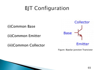
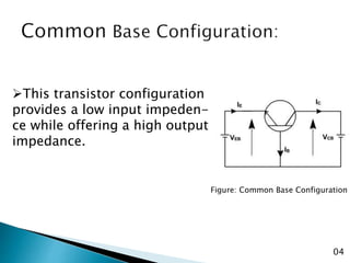
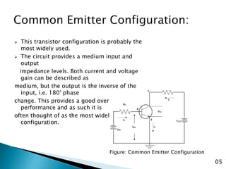
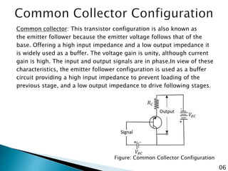
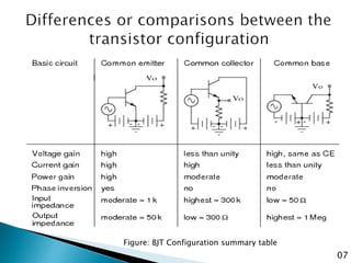
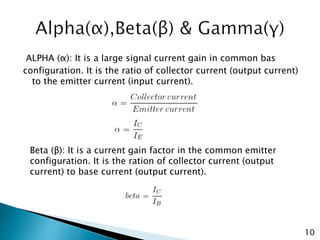
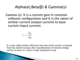
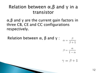
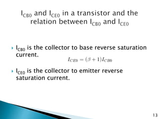
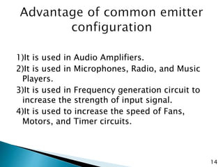
Presented by:
Saruar Chowdhury
ID:182-115-013
CSE 45th
Presented to
Kazi Wohiduzzaman
Assistant Professor
Department of EEE
Course: CSE 131; Basic Electronics Engineering
 Types of transistor configurations.
 Common Base configuration.
 Common Emitter configuration.
 Common Collector configuration.
 Best one.
 Alpha , Beta and Gamma.
 Advantage & Disadvantage of common
Emitter configuration.
02
(i)Common Base
(ii)Common Emitter
(iii)Common Collector
Figure: Bipolar Junction Transistor
03
Figure: Common Base Configuration
This transistor configuration
provides a low input impeden-
ce while offering a high output
impedance.
04
 This transistor configuration is probably the
most widely used.
 The circuit provides a medium input and
output
impedance levels. Both current and voltage
gain can be described as
medium, but the output is the inverse of the
input, i.e. 180° phase
change. This provides a good overall
performance and as such it is
often thought of as the most widely used
configuration.
Figure: Common Emitter Configuration
05
Common collector: This transistor configuration is also known as
the emitter follower because the emitter voltage follows that of the
base. Offering a high input impedance and a low output impedance it
is widely used as a buffer. The voltage gain is unity, although current
gain is high. The input and output signals are in phase.In view of these
characteristics, the emitter follower configuration is used as a buffer
circuit providing a high input impedance to prevent loading of the
previous stage, and a low output impedance to drive following stages.
Figure: Common Collector Configuration
06
Figure: BJT Configuration summary table
07
ALPHA (α): It is a large signal current gain in common bas
configuration. It is the ratio of collector current (output current)
to the emitter current (input current).
Beta (β): It is a current gain factor in the common emitter
configuration. It is the ration of collector current (output
current) to base current (output current).
10
Gamma (γ): It is a current gain in common
collector configuration and It is the ration of
emitter current (output current) to base
current (input current).
It is also called emitter efficiency that how much current is injected
from the emitter to base after recombination of minority charge
carriers in base. It’s value is high compared to α,β.
11
Alpha(α),Beta(β) & Gamma(γ)
Relation between α,β and γ in a
transistor
12
α,β and γ are the current gain factors in
three CB, CE and CC configurations
respectively.
Relation between α, β and γ :
 ICB0 is the collector to base reverse saturation
current.
 ICE0 is the collector to emitter reverse
saturation current.
13
1)It is used in Audio Amplifiers.
2)It is used in Microphones, Radio, and Music
Players.
3)It is used in Frequency generation circuit to
increase the strength of input signal.
4)It is used to increase the speed of Fans,
Motors, and Timer circuits.
14
1)It has a tendency to become noisy with age
especially in moist climate.
2)The voltage gain reduces at low as well as
high frequencies.
3)It provides poor impedance matching and
hence it cannot be used as a final stage of an
amplifier.
15
Thank You

Presentation on bjt configuration

  • 1.
    Presented by: Saruar Chowdhury ID:182-115-013 CSE45th Presented to Kazi Wohiduzzaman Assistant Professor Department of EEE Course: CSE 131; Basic Electronics Engineering
  • 2.
     Types oftransistor configurations.  Common Base configuration.  Common Emitter configuration.  Common Collector configuration.  Best one.  Alpha , Beta and Gamma.  Advantage & Disadvantage of common Emitter configuration. 02
  • 3.
    (i)Common Base (ii)Common Emitter (iii)CommonCollector Figure: Bipolar Junction Transistor 03
  • 4.
    Figure: Common BaseConfiguration This transistor configuration provides a low input impeden- ce while offering a high output impedance. 04
  • 5.
     This transistorconfiguration is probably the most widely used.  The circuit provides a medium input and output impedance levels. Both current and voltage gain can be described as medium, but the output is the inverse of the input, i.e. 180° phase change. This provides a good overall performance and as such it is often thought of as the most widely used configuration. Figure: Common Emitter Configuration 05
  • 6.
    Common collector: Thistransistor configuration is also known as the emitter follower because the emitter voltage follows that of the base. Offering a high input impedance and a low output impedance it is widely used as a buffer. The voltage gain is unity, although current gain is high. The input and output signals are in phase.In view of these characteristics, the emitter follower configuration is used as a buffer circuit providing a high input impedance to prevent loading of the previous stage, and a low output impedance to drive following stages. Figure: Common Collector Configuration 06
  • 7.
    Figure: BJT Configurationsummary table 07
  • 8.
    ALPHA (α): Itis a large signal current gain in common bas configuration. It is the ratio of collector current (output current) to the emitter current (input current). Beta (β): It is a current gain factor in the common emitter configuration. It is the ration of collector current (output current) to base current (output current). 10
  • 9.
    Gamma (γ): Itis a current gain in common collector configuration and It is the ration of emitter current (output current) to base current (input current). It is also called emitter efficiency that how much current is injected from the emitter to base after recombination of minority charge carriers in base. It’s value is high compared to α,β. 11 Alpha(α),Beta(β) & Gamma(γ)
  • 10.
    Relation between α,βand γ in a transistor 12 α,β and γ are the current gain factors in three CB, CE and CC configurations respectively. Relation between α, β and γ :
  • 11.
     ICB0 isthe collector to base reverse saturation current.  ICE0 is the collector to emitter reverse saturation current. 13
  • 12.
    1)It is usedin Audio Amplifiers. 2)It is used in Microphones, Radio, and Music Players. 3)It is used in Frequency generation circuit to increase the strength of input signal. 4)It is used to increase the speed of Fans, Motors, and Timer circuits. 14
  • 13.
    1)It has atendency to become noisy with age especially in moist climate. 2)The voltage gain reduces at low as well as high frequencies. 3)It provides poor impedance matching and hence it cannot be used as a final stage of an amplifier. 15
  • 14.