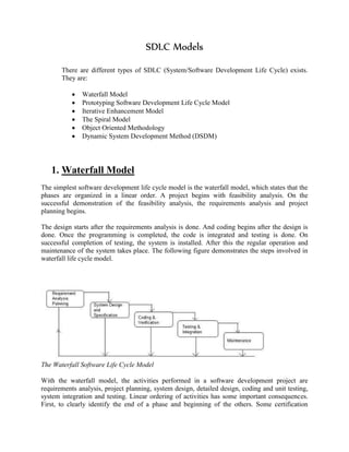
The document discusses several software development life cycle (SDLC) models: waterfall model, prototyping model, iterative enhancement model, spiral model, and object-oriented methodology model. It provides detailed descriptions of each model's phases, process, advantages, and limitations. The waterfall model is the simplest and involves sequential phases of requirements, design, implementation, testing, and maintenance. Prototyping and iterative enhancement models allow for more user feedback and flexibility. The spiral model is risk-driven and iterative. The object-oriented model focuses on identifying system objects and relationships.
Secure Software Development Lifecycle - Devoxx MA 2018Imola Informatica
Slides from our talk @Devoxx MA 2018.
We discuss Secure Software Development Lifecycle practices, recommendations, and tools, and we show practical examples of bad progamming habits that can be mitigated.
Secure Software Development Lifecycle - Devoxx MA 2018Imola Informatica
Slides from our talk @Devoxx MA 2018.
We discuss Secure Software Development Lifecycle practices, recommendations, and tools, and we show practical examples of bad progamming habits that can be mitigated.
In systems engineering and software engineering, requirements analysis encompasses those tasks that go into determining the needs or conditions to meet for a new or altered product or project, taking account of the possibly conflicting requirements of the various stakeholders, analyzing, documenting, validating and managing software or system requirements.
The ‘Multi Banking System’ Interface is targeted to the future banking solution for the users who have multiple bank accounts in different banks. This interface integrates all existing banks and provides business solutions for both retail and corporate. System Involves
• This interface integrates all existing banks and provides business solutions for both retailers and corporate.
• This system acts as a standard interface between the clients and the banks
• Users who have accounts in various banks can log in here and can make any kind of transactions.
• In the backend, the system will take care of the entire obligation required in order to carry on transaction smoothly.
The Multi Banking System Interface is targeted to the future banking solution for the users who are having multiple bank accounts in multiple banks. This interface integrates all existing banks and provides business solutions for both retail and corporate. This system acts as a standard interface between the clients and all the banks, By using this portal any client who maintains accounts in various banks can directly log on to Multi Banking System Interface and make any kind of transactions. In the backend, the system will take care of the entire obligation required in order to carry on transaction smoothly.
Explain Hardware and Software technologies used in your project work.
Define the objective and motivation of your mini-project Work in reference to your Project Title.
Present and Explain DFDs of Project (DFD-0, DFD-1, DFD-2 …).
Present and Explain ER Diagram of Project.
Explain Front-End or User Interfaces (One by One) with Purpose and working.
Explain Back-End or Database Tables used in your project.
Explain Usability or Ultimate output of your project work.
Explain the Drawback or limitations of your project work.
Explain how this work can be carried out in future for improvement.
Software Product Measurement and Analysis in a Continuous Integration Environ...Gabriel Moreira
Presentation of a paper presented in the International Conference ITNG 2010, about a framework constructed for software internal quality measurement program with automatic metrics extraction, implemented at a Software Factory.
Benchmarking is the process of improving performance by continuously identifying, understanding, and adapting outstanding practices found inside and outside the organization.
It is a methodology used to develop and refine an organization’s software development process. CMM can be used to assess an organization against a scale of five process maturity levels based on certain Key Process Areas (KPA). It describes the maturity of the company based upon the project the company is dealing with and the clients.
Process models are not perfect, but provide road map for software engineering work. Software models provide stability, control, and organization to a process that if not managed can easily get out of control
Software process models are adapted to meet the needs of software engineers and managers for a specific project.
Waterfall Model in SDLC system development life Cycle this model is used to developed software according to the requirement of the Users.... in any business this model is using commonly
Evolution of software; Characteristics of software; Software applications; Components of software; Software myths; Software problems; Software reuse; Overview of risk management; Process visibility; Professional responsibility.
This is about software engineering.Software engineers apply engineering principles and knowledge of programming languages to build software solutions for end users. Software engineers design and develop computer games, business applications, operating systems, network control systems, and middleware—to name just a few of the many career paths available.
The waterfall model is a sequential (non-iterative) design process, used in software development processes, in which progress is seen as flowing steadily downwards (like a waterfall) through the phases of conception, initiation, analysis, design, construction, testing, production/implementation and maintenance.
This is a powerpoint presentation on Software Develoment Life Cycle.The software development life cycle (SDLC) is a framework defining tasks performed at each step in the software development process
Unit 8 - Information and Communication Technology (Paper I).pdfThiyagu K
This slides describes the basic concepts of ICT, basics of Email, Emerging Technology and Digital Initiatives in Education. This presentations aligns with the UGC Paper I syllabus.
Palestine last event orientationfvgnh .pptxRaedMohamed3
An EFL lesson about the current events in Palestine. It is intended to be for intermediate students who wish to increase their listening skills through a short lesson in power point.
Macroeconomics- Movie Location
This will be used as part of your Personal Professional Portfolio once graded.
Objective:
Prepare a presentation or a paper using research, basic comparative analysis, data organization and application of economic information. You will make an informed assessment of an economic climate outside of the United States to accomplish an entertainment industry objective.
Introduction to AI for Nonprofits with Tapp NetworkTechSoup
Dive into the world of AI! Experts Jon Hill and Tareq Monaur will guide you through AI's role in enhancing nonprofit websites and basic marketing strategies, making it easy to understand and apply.
June 3, 2024 Anti-Semitism Letter Sent to MIT President Kornbluth and MIT Cor...Levi Shapiro
Letter from the Congress of the United States regarding Anti-Semitism sent June 3rd to MIT President Sally Kornbluth, MIT Corp Chair, Mark Gorenberg
Dear Dr. Kornbluth and Mr. Gorenberg,
The US House of Representatives is deeply concerned by ongoing and pervasive acts of antisemitic
harassment and intimidation at the Massachusetts Institute of Technology (MIT). Failing to act decisively to ensure a safe learning environment for all students would be a grave dereliction of your responsibilities as President of MIT and Chair of the MIT Corporation.
This Congress will not stand idly by and allow an environment hostile to Jewish students to persist. The House believes that your institution is in violation of Title VI of the Civil Rights Act, and the inability or
unwillingness to rectify this violation through action requires accountability.
Postsecondary education is a unique opportunity for students to learn and have their ideas and beliefs challenged. However, universities receiving hundreds of millions of federal funds annually have denied
students that opportunity and have been hijacked to become venues for the promotion of terrorism, antisemitic harassment and intimidation, unlawful encampments, and in some cases, assaults and riots.
The House of Representatives will not countenance the use of federal funds to indoctrinate students into hateful, antisemitic, anti-American supporters of terrorism. Investigations into campus antisemitism by the Committee on Education and the Workforce and the Committee on Ways and Means have been expanded into a Congress-wide probe across all relevant jurisdictions to address this national crisis. The undersigned Committees will conduct oversight into the use of federal funds at MIT and its learning environment under authorities granted to each Committee.
• The Committee on Education and the Workforce has been investigating your institution since December 7, 2023. The Committee has broad jurisdiction over postsecondary education, including its compliance with Title VI of the Civil Rights Act, campus safety concerns over disruptions to the learning environment, and the awarding of federal student aid under the Higher Education Act.
• The Committee on Oversight and Accountability is investigating the sources of funding and other support flowing to groups espousing pro-Hamas propaganda and engaged in antisemitic harassment and intimidation of students. The Committee on Oversight and Accountability is the principal oversight committee of the US House of Representatives and has broad authority to investigate “any matter” at “any time” under House Rule X.
• The Committee on Ways and Means has been investigating several universities since November 15, 2023, when the Committee held a hearing entitled From Ivory Towers to Dark Corners: Investigating the Nexus Between Antisemitism, Tax-Exempt Universities, and Terror Financing. The Committee followed the hearing with letters to those institutions on January 10, 202
Embracing GenAI - A Strategic ImperativePeter Windle
Artificial Intelligence (AI) technologies such as Generative AI, Image Generators and Large Language Models have had a dramatic impact on teaching, learning and assessment over the past 18 months. The most immediate threat AI posed was to Academic Integrity with Higher Education Institutes (HEIs) focusing their efforts on combating the use of GenAI in assessment. Guidelines were developed for staff and students, policies put in place too. Innovative educators have forged paths in the use of Generative AI for teaching, learning and assessments leading to pockets of transformation springing up across HEIs, often with little or no top-down guidance, support or direction.
This Gasta posits a strategic approach to integrating AI into HEIs to prepare staff, students and the curriculum for an evolving world and workplace. We will highlight the advantages of working with these technologies beyond the realm of teaching, learning and assessment by considering prompt engineering skills, industry impact, curriculum changes, and the need for staff upskilling. In contrast, not engaging strategically with Generative AI poses risks, including falling behind peers, missed opportunities and failing to ensure our graduates remain employable. The rapid evolution of AI technologies necessitates a proactive and strategic approach if we are to remain relevant.
How to Make a Field invisible in Odoo 17Celine George
It is possible to hide or invisible some fields in odoo. Commonly using “invisible” attribute in the field definition to invisible the fields. This slide will show how to make a field invisible in odoo 17.
Synthetic Fiber Construction in lab .pptxPavel ( NSTU)
Synthetic fiber production is a fascinating and complex field that blends chemistry, engineering, and environmental science. By understanding these aspects, students can gain a comprehensive view of synthetic fiber production, its impact on society and the environment, and the potential for future innovations. Synthetic fibers play a crucial role in modern society, impacting various aspects of daily life, industry, and the environment. ynthetic fibers are integral to modern life, offering a range of benefits from cost-effectiveness and versatility to innovative applications and performance characteristics. While they pose environmental challenges, ongoing research and development aim to create more sustainable and eco-friendly alternatives. Understanding the importance of synthetic fibers helps in appreciating their role in the economy, industry, and daily life, while also emphasizing the need for sustainable practices and innovation.
Biological screening of herbal drugs: Introduction and Need for
Phyto-Pharmacological Screening, New Strategies for evaluating
Natural Products, In vitro evaluation techniques for Antioxidants, Antimicrobial and Anticancer drugs. In vivo evaluation techniques
for Anti-inflammatory, Antiulcer, Anticancer, Wound healing, Antidiabetic, Hepatoprotective, Cardio protective, Diuretics and
Antifertility, Toxicity studies as per OECD guidelines
Francesca Gottschalk - How can education support child empowerment.pptxEduSkills OECD
Francesca Gottschalk from the OECD’s Centre for Educational Research and Innovation presents at the Ask an Expert Webinar: How can education support child empowerment?
Francesca Gottschalk - How can education support child empowerment.pptx
SDLC Model
1. SDLC Models
There are different types of SDLC (System/Software Development Life Cycle) exists.
They are:
Waterfall Model
Prototyping Software Development Life Cycle Model
Iterative Enhancement Model
The Spiral Model
Object Oriented Methodology
Dynamic System Development Method (DSDM)
1. Waterfall Model
The simplest software development life cycle model is the waterfall model, which states that the
phases are organized in a linear order. A project begins with feasibility analysis. On the
successful demonstration of the feasibility analysis, the requirements analysis and project
planning begins.
The design starts after the requirements analysis is done. And coding begins after the design is
done. Once the programming is completed, the code is integrated and testing is done. On
successful completion of testing, the system is installed. After this the regular operation and
maintenance of the system takes place. The following figure demonstrates the steps involved in
waterfall life cycle model.
The Waterfall Software Life Cycle Model
With the waterfall model, the activities performed in a software development project are
requirements analysis, project planning, system design, detailed design, coding and unit testing,
system integration and testing. Linear ordering of activities has some important consequences.
First, to clearly identify the end of a phase and beginning of the others. Some certification
2. mechanism has to be employed at the end of each phase. This is usually done by some
verification and validation. Validation means confirming the output of a phase is consistent with
its input (which is the output of the previous phase) and that the output of the phase is consistent
with overall requirements of the system.
The consequences of the need of certification is that each phase must have some defined output
that can be evaluated and certified. Therefore, when the activities of a phase are completed, there
should be an output product of that phase and the goal of a phase is to produce this product. The
outputs of the earlier phases are often called intermediate products or design document. For the
coding phase, the output is the code. From this point of view, the output of a software project is
to justify the final program along with the use of documentation with the requirements
document, design document, project plan, test plan and test results.
Another implication of the linear ordering of phases is that after each phase is completed and its
outputs are certified, these outputs become the inputs to the next phase and should not be
changed or modified. However, changing requirements cannot be avoided and must be faced.
Since changes performed in the output of one phase affect the later phases, that might have been
performed. These changes have to made in a controlled manner after evaluating the effect of
each change on the project .This brings us to the need for configuration control or configuration
management.
The certified output of a phase that is released for the best phase is called baseline. The
configuration management ensures that any changes to a baseline are made after careful review,
keeping in mind the interests of all parties that are affected by it. There are two basic
assumptions for justifying the linear ordering of phase in the manner proposed by the waterfall
model.
For a successful project resulting in a successful product, all phases listed in the waterfall model
must be performed anyway.
Any different ordering of the phases will result in a less successful software product.
Project Output in a Waterfall Model
As we have seen, the output of a project employing the waterfall model is not just the final
program along with documentation to use it. There are a number of intermediate outputs, which
must be produced in order to produce a successful product.
The set of documents that forms the minimum that should be produced in each project are:
Requirement document
Project plan
System design document
Detailed design document
Test plan and test report
Final code
3. Software manuals (user manual, installation manual etc.)
Review reports
Except for the last one, these are all the outputs of the phases. In order to certify an output
product of a phase before the next phase begins, reviews are often held. Reviews are necessary
especially for the requirements and design phases, since other certification means are frequently
not available. Reviews are formal meeting to uncover deficiencies in a product. The review
reports are the outcome of these reviews.
Advantages of Waterfall Life Cycle Models
1. Easy to explain to the user
2. Stages and activities are well defined
3. Helps to plan and schedule the project
4. Verification at each stage ensures early detection of errors / misunderstanding
Limitations of the Waterfall Life Cycle Model
The waterfall model assumes that the requirements of a system can be frozen (i.e. basedline)
before the design begins. This is possible for systems designed to automate an existing manual
system. But for absolutely new system, determining the requirements is difficult, as the user
himself does not know the requirements. Therefore, having unchanging (or changing only a few)
requirements is unrealistic for such project.
Freezing the requirements usually requires choosing the hardware (since it forms a part of the
requirement specification). A large project might take a few years to complete. If the hardware is
selected early, then due to the speed at which hardware technology is changing, it is quite likely
that the final software will employ a hardware technology that is on the verge of becoming
obsolete. This is clearly not desirable for such expensive software.
The waterfall model stipulates that the requirements should be completely specified before the
rest of the development can proceed. In some situations it might be desirable to first develop a
part of the system completely, an then later enhance the system in phase. This is often done for
software products that are developed not necessarily for a client (where the client plays an
important role in requirement specification), but for general marketing, in which the
requirements are likely to be determined largely by developers.
2. Prototyping Model
The goal of prototyping based development is to counter the first two limitations of the waterfall
model discussed earlier. The basic idea here is that instead of freezing the requirements before a
design or coding can proceed, a throwaway prototype is built to understand the requirements.
This prototype is developed based on the currently known requirements. Development of the
prototype obviously undergoes design, coding and testing. But each of these phases is not done
4. very formally or thoroughly. By using this prototype, the client can get an "actual feel" of the
system, since the interactions with prototype can enable the client to better understand the
requirements of the desired system.
Prototyping is an attractive idea for complicated and large systems for which there is no manual
process or existing system to help determining the requirements. In such situations letting the
client "plan" with the prototype provides invaluable and intangible inputs which helps in
determining the requirements for the system. It is also an effective method to demonstrate the
feasibility of a certain approach. This might be needed for novel systems where it is not clear that
constraints can be met or that algorithms can be developed to implement the requirements. The
process model of the prototyping approach is shown in the figure below.
Prototyping Model
The basic reason for little common use of prototyping is the cost involved in this built-it-twice
approach. However, some argue that prototyping need not be very costly and can actually reduce
the overall development cost. The prototype are usually not complete systems and many of the
details are not built in the prototype. The goal is to provide a system with overall functionality.
In addition, the cost of testing and writing detailed documents are reduced. These factors helps to
reduce the cost of developing the prototype. On the other hand, the experience of developing the
prototype will very useful for developers when developing the final system. This experience
helps to reduce the cost of development of the final system and results in a more reliable and
better designed system.
Advantages of Prototyping
1. Users are actively involved in the development
2. It provides a better system to users, as users have natural tendency to change their mind
in specifying requirements and this method of developing systems supports this user
tendency.
3. Since in this methodology a working model of the system is provided, the users get a
better understanding of the system being developed.
4. Errors can be detected much earlier as the system is mode side by side.
5. Quicker user feedback is available leading to better solutions.
Disadvantages
1. Leads to implementing and then repairing way of building systems.
5. 2. Practically, this methodology may increase the complexity of the system as scope of the
system may expand beyond original plans.
3. The Iterative Enhancement Model
The iterative enhancement life cycle model counters the third limitation of the waterfall model
and tries to combine the benefits of both prototyping and the waterfall model. The basic idea is
that the software should be developed in increments, where each increment adds some functional
capability to the system until the full system is implemented. At each step extensions and design
modifications can be made. An advantage of this approach is that it can result in better testing,
since testing each increment is likely to be easier than testing entire system like in the waterfall
model. Furthermore, as in prototyping, the increments provides feedback to the client which is
useful for determining the final requirements of the system.
In the first step of iterative enhancement model, a simple initial implementation is done for a
subset of the overall problem. This subset is the one that contains some of the key aspects of the
problem which are easy to understand and implement, and which forms a useful and usable
system. A project control list is created which contains, in an order, all the tasks that must be
performed to obtain the final implementation. This project control list gives an idea of how far
the project is at any given step from the final system.
Each step consists of removing the next step from the list. Designing the implementation for the
selected task, coding and testing the implementation, and performing an analysis of the partial
system obtained after this step and updating the list as a result of the analysis. These three phases
are called the design phase, implementation phase and analysis phase. The process is iterated
until the project control list is empty, at the time the final implementation of the system will be
available. The process involved in iterative enhancement model is shown in the figure below.
The Iterative Enhancement Model
The project control list guides the iteration steps and keeps track of all tasks that must be done.
The tasks in the list can be include redesign of defective components found during analysis. Each
entry in that list is a task that should be performed in one step of the iterative enhancement
process, and should be simple enough to be completely understood. Selecting tasks in this
manner will minimize the chances of errors and reduce the redesign work.
4. Spiral Model
6. This is a recent model that has been proposed by Boehm. As the name suggests, the activities in
this model can be organized like a spiral. The spiral has many cycles. The radial dimension
represents the cumulative cost incurred in accomplishing the steps dome so far and the angular
dimension represents the progress made in completing each cycle of the spiral. The structure of
the spiral model is shown in the figure given below. Each cycle in the spiral begins with the
identification of objectives for that cycle and the different alternatives are possible for achieving
the objectives and the imposed constraints.
The next step in the spiral life cycle model is to evaluate these different alternatives based on the
objectives and constraints. This will also involve identifying uncertainties and risks involved.
The next step is to develop strategies that resolve the uncertainties and risks. This step may
involve activities such as benchmarking, simulation and prototyping. Next, the software is
developed by keeping in mind the risks. Finally the next stage is planned.
The next step is determined by remaining risks. For example, its performance or user-interface
risks are considered more important than the program development risks. The next step may be
evolutionary development that involves developing a more detailed prototype for resolving the
risks. On the other hand, if the program development risks dominate and previous prototypes
have resolved all the user-interface and performance risks; the next step will follow the basic
waterfall approach.
7. The risk driven nature of the spiral model allows it to accommodate any mixture of specification-oriented,
prototype-oriented, simulation-oriented or some other approach. An important feature
of the model is that each cycle of the spiral is completed by a review, which covers all the
products developed during that cycle, including plans for the next cycle. The spiral model works
for developed as well as enhancement projects.
Spiral Model Description
The development spiral consists of four quadrants as shown in the figure above
Quadrant 1: Determine objectives, alternatives, and constraints.
Quadrant 2: Evaluate alternatives, identify, resolve risks.
Quadrant 3: Develop, verify, next-level product.
Quadrant 4: Plan next phases.
Although the spiral, as depicted, is oriented toward software development, the concept is equally
applicable to systems, hardware, and training, for example. To better understand the scope of
each spiral development quadrant, let’s briefly address each one.
Quadrant 1: Determine Objectives, Alternatives, and Constraints
Activities performed in this quadrant include:
1. Establish an understanding of the system or product objectives—namely performance,
functionality, and ability to accommodate change.
2. Investigate implementation alternatives—namely design, reuse, procure, and procure/
modify
3. Investigate constraints imposed on the alternatives—namely technology, cost, schedule,
support, and risk. Once the system or product’s objectives, alternatives, and constraints
are understood, Quadrant 2 (Evaluate alternatives, identify, and resolve risks) is
performed.
Quadrant 2: Evaluate Alternatives, Identify, Resolve Risks
Engineering activities performed in this quadrant select an alternative approach that best satisfies
technical, technology, cost, schedule, support, and risk constraints. The focus here is on risk
mitigation. Each alternative is investigated and prototyped to reduce the risk associated with the
development decisions. Boehm describes these activities as follows:
. . . This may involve prototyping, simulation, benchmarking, reference checking, administering
user
questionnaires, analytic modeling, or combinations of these and other risk resolution techniques.
8. The outcome of the evaluation determines the next course of action. If critical operational and/or
technical issues (COIs/CTIs) such as performance and interoperability (i.e., external and internal)
risks remain, more detailed prototyping may need to be added before progressing to the next
quadrant. Dr. Boehm notes that if the alternative chosen is “operationally useful and robust
enough to serve as a low-risk base for future product evolution, the subsequent risk-driven steps
would be the evolving series of evolutionary prototypes going toward the right (hand side of the
graphic) . . . the option of writing specifications would be addressed but not exercised.” This
brings us to Quadrant 3.
Quadrant 3: Develop, Verify, Next-Level Product
If a determination is made that the previous prototyping efforts have resolved the COIs/CTIs,
activities to develop, verify, next-level product are performed. As a result, the basic “waterfall”
approach may be employed—meaning concept of operations, design, development, integration,
and test of the next system or product iteration. If appropriate, incremental development
approaches may also be applicable.
Quadrant 4: Plan Next Phases
The spiral development model has one characteristic that is common to all models—the need for
advanced technical planning and multidisciplinary reviews at critical staging or control points.
Each cycle of the model culminates with a technical review that assesses the status, progress,
maturity, merits, risk, of development efforts to date; resolves critical operational and/or
technical issues (COIs/CTIs); and reviews plans and identifies COIs/CTIs to be resolved for the
next iteration of the spiral.
Subsequent implementations of the spiral may involve lower level spirals that follow the same
quadrant paths and decision considerations.
5. Object Oriented Methodology Life Cycle Model
We live in a world of objects. These objects exist in nature, in man-made entities, in business,
and in the products that we use. They can be categorized, described, organized, combined,
manipulated and created. Therefore, an object-oriented view has come into picture for creation of
computer software. An object-oriented approach to the development of software was proposed in
late 1960s.
Object-Oriented development requires that object-oriented techniques be used during the
analysis, and implementation of the system. This methodology asks the analyst to determine
what the objects of the system are, how they behave over time or in response to events, and what
responsibilities and relationships an object has to other objects. Object-oriented analysis has the
analyst look at all the objects in a system, their commonalties, difference, and how the system
needs to manipulate the objects.
9. Object Oriented Process
The Object Oriented Methodology of Building Systems takes the objects as the basis. For this,
first the system to be developed is observed and analyzed and the requirements are defined as in
any other method of system development. Once this is done, the objects in the required system
are identified. For example in case of a Banking System, a customer is an object, a chequebook
is an object, and even an account is an object.
In simple terms, Object Modeling is based on identifying the objects in a system and their
interrelationships. Once this is done, the coding of the system is done. Object Modeling is
somewhat similar to the traditional approach of system designing, in that it also follows a
sequential process of system designing but with a different approach. The basic steps of system
designing using Object Modeling may be listed as:
System Analysis
System Design
Object Design
Implementation
System Analysis
As in any other system development model, system analysis is the first phase of development in
case of Object Modeling too. In this phase, the developer interacts with the user of the system to
find out the user requirements and analyses the system to understand the functioning.
Based on this system study, the analyst prepares a model of the desired system. This model is
purely based on what the system is required to do. At this stage the implementation details are
not taken care of. Only the model of the system is prepared based on the idea that the system is
made up of a set of interacting objects. The important elements of the system are emphasized.
System Design
System Design is the next development stage where the overall architecture of the desired system
is decided. The system is organized as a set of sub systems interacting with each other. While
designing the system as a set of interacting subsystems, the analyst takes care of specifications as
observed in system analysis as well as what is required out of the new system by the end user.
As the basic philosophy of Object-Oriented method of system analysis is to perceive the system
as a set of interacting objects, a bigger system may also be seen as a set of interacting smaller
subsystems that in turn are composed of a set of interacting objects. While designing the system,
the stress lies on the objects comprising the system and not on the processes being carried out in
the system as in the case of traditional Waterfall Model where the processes form the important
part of the system.
Object Design
10. In this phase, the details of the system analysis and system design are implemented. The Objects
identified in the system design phase are designed. Here the implementation of these objects is
decided as the data structures get defined and also the interrelationships between the objects are
defined.
Let us here deviate slightly from the design process and understand first a few important terms
used in the Object-Oriented Modeling.
As already discussed, Object Oriented Philosophy is very much similar to real world and hence
is gaining popularity as the systems here are seen as a set of interacting objects as in the real
world. To implement this concept, the process-based structural programming is not used; instead
objects are created using data structures. Just as every programming language provides various
data types and various variables of that type can be created, similarly, in case of objects certain
data types are predefined.
For example, we can define a data type called pen and then create and use several objects of this
data type. This concept is known as creating a class.
Class: A class is a collection of similar objects. It is a template where certain basic
characteristics of a set of objects are defined. The class defines the basic attributes and the
operations of the objects of that type. Defining a class does not define any object, but it only
creates a template. For objects to be actually created instances of the class are created as per the
requirement of the case.
Abstraction: Classes are built on the basis of abstraction, where a set of similar objects are
observed and their common characteristics are listed. Of all these, the characteristics of concern
to the system under observation are picked up and the class definition is made. The attributes of
no concern to the system are left out. This is known as abstraction.
The abstraction of an object varies according to its application. For instance, while defining a
pen class for a stationery shop, the attributes of concern might be the pen color, ink color, pen
type etc., whereas a pen class for a manufacturing firm would be containing the other dimensions
of the pen like its diameter, its shape and size etc.
Inheritance: Inheritance is another important concept in this regard. This concept is used to
apply the idea of reusability of the objects. A new type of class can be defined using a similar
existing class with a few new features. For instance, a class vehicle can be defined with the basic
functionality of any vehicle and a new class called car can be derived out of it with a few
modifications. This would save the developers time and effort as the classes already existing are
reused without much change.
Coming back to our development process, in the Object Designing phase of the Development
process, the designer decides onto the classes in the system based on these concepts. The
designer also decides on whether the classes need to be created from scratch or any existing
classes can be used as it is or new classes can be inherited from them.
11. Implementation
During this phase, the class objects and the interrelationships of these classes are translated and
actually coded using the programming language decided upon. The databases are made and the
complete system is given a functional shape.
The complete OO methodology revolves around the objects identified in the system. When
observed closely, every object exhibits some characteristics and behavior. The objects recognize
and respond to certain events. For example, considering a Window on the screen as an object, the
size of the window gets changed when resize button of the window is clicked.
Here the clicking of the button is an event to which the window responds by changing its state
from the old size to the new size. While developing systems based on this approach, the analyst
makes use of certain models to analyze and depict these objects. The methodology supports and
uses three basic Models:
Object Model - This model describes the objects in a system and their interrelationships.
This model observes all the objects as static and does not pay any attention to their
dynamic nature.
Dynamic Model - This model depicts the dynamic aspects of the system. It portrays the
changes occurring in the states of various objects with the events that might occur in the
system.
Functional Model - This model basically describes the data transformations of the
system. This describes the flow of data and the changes that occur to the data throughout
the system.
While the Object Model is most important of all as it describes the basic element of the system,
the objects, all the three models together describe the complete functional system.
As compared to the conventional system development techniques, OO modeling provides many
benefits. Among other benefits, there are all the benefits of using the Object Orientation. Some
of these are:
Reusability - The classes once defined can easily be used by other applications. This is
achieved by defining classes and putting them into a library of classes where all the
classes are maintained for future use. Whenever a new class is needed the programmer
looks into the library of classes and if it is available, it can be picked up directly from
there.
Inheritance - The concept of inheritance helps the programmer use the existing code in
another way, where making small additions to the existing classes can quickly create new
classes.
Programmer has to spend less time and effort and can concentrate on other aspects of the
system due to the reusability feature of the methodology.
Data Hiding - Encapsulation is a technique that allows the programmer to hide the
internal functioning of the objects from the users of the objects. Encapsulation separates
the internal functioning of the object from the external functioning thus providing the
12. user flexibility to change the external behaviour of the object making the programmer
code safe against the changes made by the user.
The systems designed using this approach are closer to the real world as the real world
functioning of the system is directly mapped into the system designed using this
approach.
Advantages of Object Oriented Methodology
Object Oriented Methodology closely represents the problem domain. Because of this, it
is easier to produce and understand designs.
The objects in the system are immune to requirement changes. Therefore, allows changes
more easily.
Object Oriented Methodology designs encourage more re-use. New applications can use
the existing modules, thereby reduces the development cost and cycle time.
Object Oriented Methodology approach is more natural. It provides nice structures for
thinking and abstracting and leads to modular design.
6. Dynamic System Development Method (DSDM)
Dynamic System Development Method is another approach to system development, which, as
the name suggests, develops the system dynamically. This methodology is independent of tools,
in that it can be used with both structured analysis and design approach or object-oriented
approach.
The Dynamic System Development Method (DSDM) is dynamic as it is a Rapid Application
Development method that uses incremental prototyping. This method is particularly useful for
the systems to be developed in short time span and where the requirements cannot be frozen at
the start of the application building. Whatever requirements are known at a time, design for them
is prepared and design is developed and incorporated into system. In Dynamic System
Development Method (DSDM), analysis, design and development phase can overlap. Like at one
time some people will be working on some new requirements while some will be developing
something for the system. In Dynamic System Development Method (DSDM), requirements
evolve with time.
Dynamic System Development Method (DSDM) has a five-phase life cycle as given the
following figure
13. Feasibility study
In this phase the problem is defined and the technical feasibility of the desired application is
verified. Apart from these routine tasks, it is also checked whether the application is suitable for
Rapid Application Development (RAD) approach or not. Only if the RAD is found as a justified
approach for the desired system, the development continues.
Business study
In this phase the overall business study of the desired system is done. The business requirements
are specified at a high level and the information requirements out of the system are identified.
Once this is done, the basic architectural framework of the desired system is prepared.
The systems designed using Rapid Application Development (RAD) should be highly
maintainable, as they are based on the incremental development process. The maintainability
level of the system is also identified here so as to set the standards for quality control activities
throughout the development process.
Functional Model Iteration
This is one of the two iterative phases of the life cycle. The main focus in this phase is on
building the prototype iteratively and getting it reviewed from the users to bring out the
requirements of the desired system. The prototype is improved through demonstration to the
user, taking the feedback and incorporating the changes. This cycle is repeated generally twice or
thrice until a part of functional model is agreed upon. The end product of this phase is a
14. functional model consisting of analysis model and some software components containing the
major functionality
Design and Build Iteration
This phase stresses upon ensuring that the prototypes are satisfactorily and properly engineered
to suit their operational environment. The software components designed during the functional
modeling are further refined till they achieve a satisfactory standard. The product of this phase is
a tested system ready for implementation.
There is no clear line between these two phases and there may be cases where while some
component has flown from the functional modeling to the design and build modeling while the
other component has not yet been started. The two phases, as a result, may simultaneously
continue.
Implementation
Implementation is the last and final development stage in this methodology. In this phase the
users are trained and the system is actually put into the operational environment. At the end of
this phase, there are four possibilities, as depicted by figure :
Everything was delivered as per the user demand, so no further development required.
A new functional area was discovered, so return to business study phase and repeat the
whole process
A less essential part of the project was missed out due to time constraint and so
development returns to the functional model iteration.
Some non-functional requirement was not satisfied, so development returns to the design
and build iterations phase.
Dynamic System Development Method (DSDM) assumes that all previous steps may be
revisited as part of its iterative approach. Therefore, the current step need be completed only
enough to move to the next step, since it can be finished in a later iteration. This premise is that
the business requirements will probably change anyway as understanding increases, so any
further work would have been wasted.
According to this approach, the time is taken as a constraint i.e. the time is fixed, resources are
fixed while the requirements are allowed to change. This does not follow the fundamental
assumption of making a perfect system the first time, but provides a usable and useful 80% of the
desired system in 20% of the total development time. This approach has proved to be very useful
under time constraints and varying requirements.
DSDM Model Limitations
It is a relatively new model. It is not very common. So it is difficult to understand.
15. DSDM Model Advantages
Active user participation throughout the life of the project and iterative nature of
development improves quality of the product.
DSDM ensures rapid deliveries.
Both of the above factors result in reduced project costs