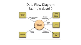
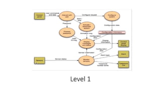
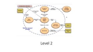
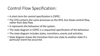
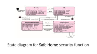
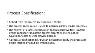
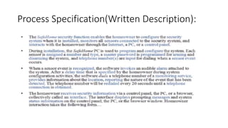
Flow Oriented Modeling
Data flow diagram
Control Flow Specification
Process Specification
Definition:
“It is based on structural analysis
technique. Structured analysis is a software
engineering technique that uses graphical
diagrams to develop and portray system
specifications that are easily understood by
users “
Guidelines:
• Depict the system as a single bubble in level 0.
• Carefully note Primary input and output.
• Always starts with level 0, level 1 and then level 2.
• In level 1 we divide our input into different processes and assign work
to each process.
• Label all elements with meaning names.
• Maintain Info conformity between levels.
• Refine one bubble at a time.
Data Flow Diagram
Example :level 0
Level 1
Level 2
Control Flow Specification:
• A short term for control specification is CSPEC.
• The CFD contains the same processes as the DFD, but shows control flow,
rather than data flow.
• It represents the behaviour of the system.
• The state diagram in CSPEC is a sequential specification of the behaviour.
• The state diagram includes states, transitions, events and activities.
• State diagram shows the transition from one state to another state if a
particular event has occurred.
State diagram for Safe Home security function
Process Specification:
• A short term for process specification is PSPEC.
• The process specification is used to describe all flow model processes.
• The content of process specification consists narrative text, Program
Design Language(PDL) of the process algorithm, mathematical
equations, tables or UML activity diagram.
• A process specification (PSPEC) can be used to specify the processing
details implied by a bubble within a DFD.
Process Specification(Written Description):

Flow oriented modeling

  • 1.
    Flow Oriented Modeling Dataflow diagram Control Flow Specification Process Specification
  • 2.
    Definition: “It is basedon structural analysis technique. Structured analysis is a software engineering technique that uses graphical diagrams to develop and portray system specifications that are easily understood by users “
  • 3.
    Guidelines: • Depict thesystem as a single bubble in level 0. • Carefully note Primary input and output. • Always starts with level 0, level 1 and then level 2. • In level 1 we divide our input into different processes and assign work to each process. • Label all elements with meaning names. • Maintain Info conformity between levels. • Refine one bubble at a time.
  • 4.
  • 5.
  • 6.
  • 7.
    Control Flow Specification: •A short term for control specification is CSPEC. • The CFD contains the same processes as the DFD, but shows control flow, rather than data flow. • It represents the behaviour of the system. • The state diagram in CSPEC is a sequential specification of the behaviour. • The state diagram includes states, transitions, events and activities. • State diagram shows the transition from one state to another state if a particular event has occurred.
  • 8.
    State diagram forSafe Home security function
  • 9.
    Process Specification: • Ashort term for process specification is PSPEC. • The process specification is used to describe all flow model processes. • The content of process specification consists narrative text, Program Design Language(PDL) of the process algorithm, mathematical equations, tables or UML activity diagram. • A process specification (PSPEC) can be used to specify the processing details implied by a bubble within a DFD.
  • 10.