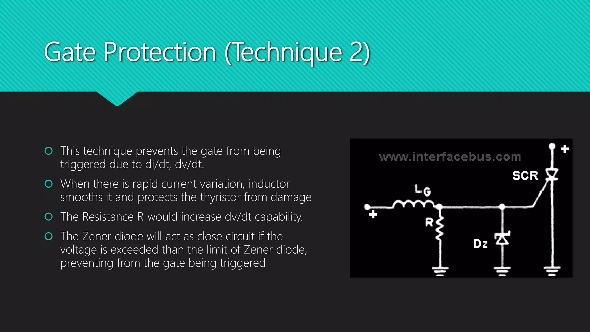
SCR Protection Techniques
Presented By:
Shahneel Siddiqui
BE-VII
Agenda
 Protection of Load using SCR Crowbar Circuits
 Gate Protection Techniques
 Thermal Protection of SCR
SCR Crowbar Circuit
 It prevents the load from getting damaged
 Simple and effective method
 Widely used for over-voltage protections
 Consists of a Zener Diode, a Resistor, and a SCR
 These components are connected between the Source & the Load
SCR Crowbar Circuit (Cont.)
 Rating of Zener Diode is kept slightly greater than normal voltage limit.
 Zener Diode Makes the crowbar circuit act as open switch at normal voltage.
 When the voltage limit increases, the Zener diode starts conducting and voltage appears across
the Resister.
 This, in turn activates the SCR because of which the voltage drop across the load is reduced.
 The gate current determines the amount of voltage to be supplied to the Load.
Gate Protection of SCR
 Gate plays an important role in normal triggering of an SCR
 Various reasons can automatically trigger the gate even if it is not desired, the reasons include
• Negative Voltages
• Dv/dt & di/dt
• Over voltages
• Over currents
• Holding & latching current
 There are various techniques to protect the gate of an SCR from these issues.
Gate Protection (Technique 1)
 This is the simplest Gate protection Technique
 This technique prevents the gate from being
triggered due to over-voltages
 The Resistance RG will limit the gate current
 The Zener diode will act as close circuit if the
voltage is exceeded than the limit of Zener diode,
preventing from the gate being triggered
Gate Protection (Technique 2)
 This technique prevents the gate from being
triggered due to di/dt, dv/dt.
 When there is rapid current variation, inductor
smooths it and protects the thyristor from damage
 The Resistance R would increase dv/dt capability.
 The Zener diode will act as close circuit if the
voltage is exceeded than the limit of Zener diode,
preventing from the gate being triggered
Gate Protection (Technique 3)
 This method prevents the Gate from every kind of
unwanted triggering.
 The Diodes are used to protect the gate from
negative voltages by rectification process
 The Resister R1 limits the current
 The Resister R2 provides dv/dt Protection
 The capacitor is removing high frequency
components.
SCR Thermal Protection
 With the increase in junction temperature, insulation of SCR may get fail.
 Proper measures are required when working with SCR on high current and temperature levels.
 A heat sink may be mounted on an SCR to prevent it from getting damaged due to heat.
 The heat sinks are made of high thermal conductivity metals, such as
 Aluminium
 Copper
 Maily Aluminum is used due to its low cost.
Types of Heat Sinks mounting
 Types of Heat Sinks mounting techniques used
 Lead Mounting
 Stud Mounting
 Bolt Down Mounting
 Press Fit Mounting
 Press Pack Mounting
 Mostly used are
 Lead Mounting
 Stud Mounting
Lead Mounting
Stud Mounting
This was it
Thankyou for your time
Questions are very much welcomed 

SCR protections

  • 1.
    SCR Protection Techniques PresentedBy: Shahneel Siddiqui BE-VII
  • 2.
    Agenda  Protection ofLoad using SCR Crowbar Circuits  Gate Protection Techniques  Thermal Protection of SCR
  • 3.
    SCR Crowbar Circuit It prevents the load from getting damaged  Simple and effective method  Widely used for over-voltage protections  Consists of a Zener Diode, a Resistor, and a SCR  These components are connected between the Source & the Load
  • 4.
  • 5.
    SCR Crowbar Circuit(Cont.)  Rating of Zener Diode is kept slightly greater than normal voltage limit.  Zener Diode Makes the crowbar circuit act as open switch at normal voltage.  When the voltage limit increases, the Zener diode starts conducting and voltage appears across the Resister.  This, in turn activates the SCR because of which the voltage drop across the load is reduced.  The gate current determines the amount of voltage to be supplied to the Load.
  • 6.
    Gate Protection ofSCR  Gate plays an important role in normal triggering of an SCR  Various reasons can automatically trigger the gate even if it is not desired, the reasons include • Negative Voltages • Dv/dt & di/dt • Over voltages • Over currents • Holding & latching current  There are various techniques to protect the gate of an SCR from these issues.
  • 7.
    Gate Protection (Technique1)  This is the simplest Gate protection Technique  This technique prevents the gate from being triggered due to over-voltages  The Resistance RG will limit the gate current  The Zener diode will act as close circuit if the voltage is exceeded than the limit of Zener diode, preventing from the gate being triggered
  • 8.
    Gate Protection (Technique2)  This technique prevents the gate from being triggered due to di/dt, dv/dt.  When there is rapid current variation, inductor smooths it and protects the thyristor from damage  The Resistance R would increase dv/dt capability.  The Zener diode will act as close circuit if the voltage is exceeded than the limit of Zener diode, preventing from the gate being triggered
  • 9.
    Gate Protection (Technique3)  This method prevents the Gate from every kind of unwanted triggering.  The Diodes are used to protect the gate from negative voltages by rectification process  The Resister R1 limits the current  The Resister R2 provides dv/dt Protection  The capacitor is removing high frequency components.
  • 10.
    SCR Thermal Protection With the increase in junction temperature, insulation of SCR may get fail.  Proper measures are required when working with SCR on high current and temperature levels.  A heat sink may be mounted on an SCR to prevent it from getting damaged due to heat.  The heat sinks are made of high thermal conductivity metals, such as  Aluminium  Copper  Maily Aluminum is used due to its low cost.
  • 11.
    Types of HeatSinks mounting  Types of Heat Sinks mounting techniques used  Lead Mounting  Stud Mounting  Bolt Down Mounting  Press Fit Mounting  Press Pack Mounting  Mostly used are  Lead Mounting  Stud Mounting
  • 12.
  • 13.
  • 14.
    This was it Thankyoufor your time Questions are very much welcomed 