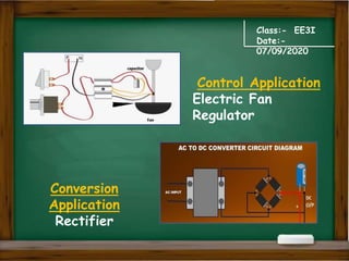
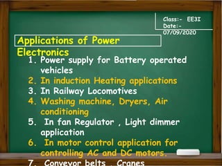
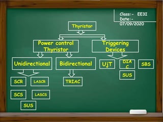
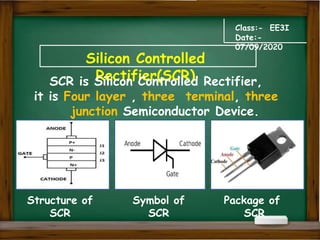
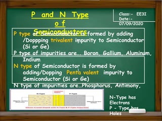
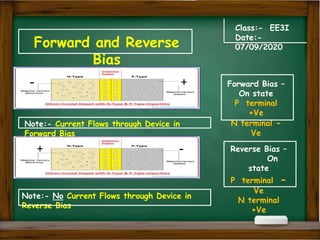
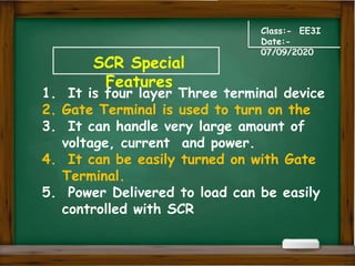
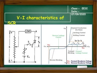
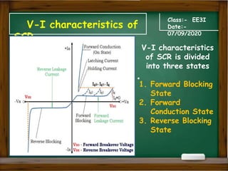
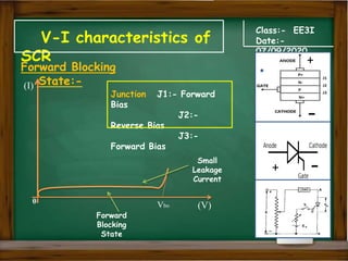
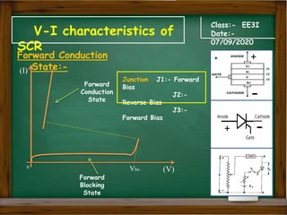
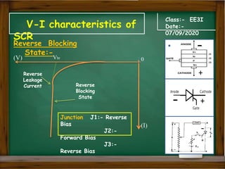
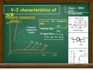
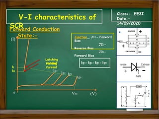
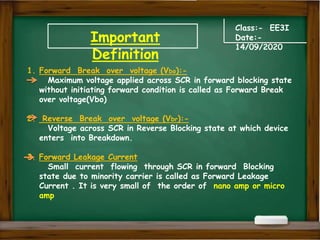
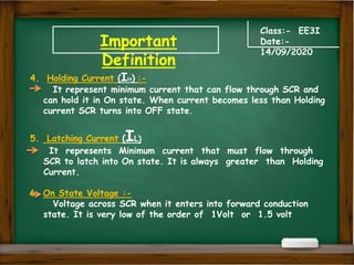
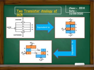
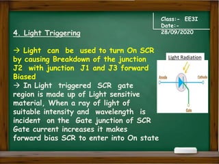
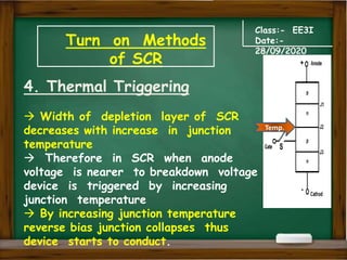
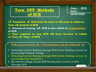
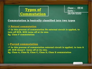
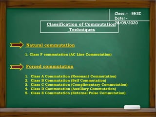
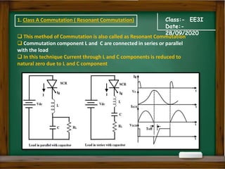
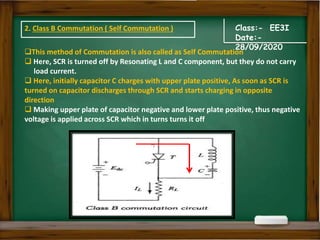
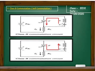
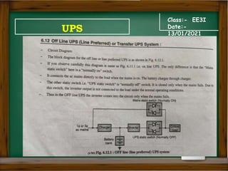
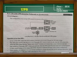
The document provides an overview of a class on fundamentals of power electronics. It covers topics like power electronics, power electronic devices, applications of power electronics, thyristors, characteristics of SCR, turn on and turn off methods of SCR, and classifications of commutation techniques. The class discusses concepts related to control and conversion of electric power using solid state devices.


![[Deck] What's New in Spark-Iceberg Integration via DSV2.pptx](https://cdn.slidesharecdn.com/ss_thumbnails/deckwhatsnewinspark-icebergintegrationviadsv2-260210005337-25955b12-thumbnail.jpg?width=640&height=640&fit=bounds)


