Downloaded 110 times

![Rubble Mound Breakwater
4
where
g is the gravitational acceleration, 9.82m/s2
Rc is the freeboard or height of elevation
som
2
0 032
62 2
s
om
H m
.
L . m
= = = , equation VI-5-2
a is a coefficient that is read to 0.013 (for straight smooth slopes)
b is a coefficient that is read to 22 (for straight smooth slopes)
γr is a coefficient that is 0.5 - 0.6, here 0.6 since this yields the biggest free-
board
Note that the wave length for the depth of 7.2m is used since this is the design wave length.
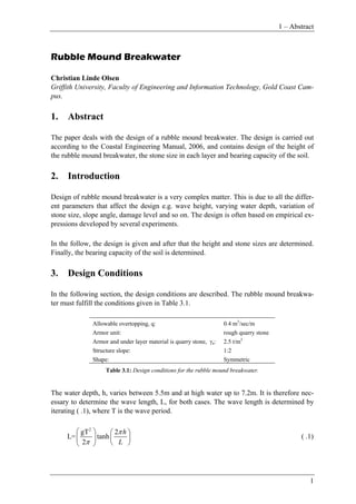
The height of the freeboard is then calculated to be 1.24m, which is illustrated in Figure
4-1.
Armor
UL1
UL2
Core
DWL
Figure 4-1: Illustration of freeboard, Rc.
Wave Run up
Wave rum up is a phenomenon caused by the breaking waves on a slope, cf. Figure 4-2.
Figure 4-2: Wave run up and run down. [CEM, 2006]](https://image.slidesharecdn.com/rubblemoundbreakwater-140404215228-phpapp02/85/Rubble-mound-breakwater-4-320.jpg)


![Rubble Mound Breakwater
8
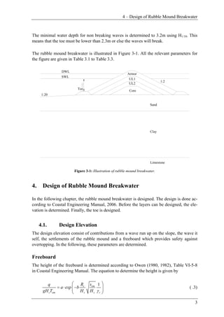
Figure 4-3: Design of layers. [CEM, 2006]
Using Figure 4-3 and equation ( .14) and ( .15) the unit weight, layer thickness and amount
of units per area are determined and the results are given in Table 4.1 where the volume of
stones for unit length is calculated using Figure 4-4
Layer
W
[t/m3
]
Dn50
[m]
r
[m]
Na
[stones/m2
]
Vol. of stones
for unit length
[m3
/m]
Armor 1.23 0.8 1.6 4.5 98
UL 1 0.12 0.37 0.8 21 46
UL 2 0.006 0.14 0.3 154 17
Toe 0.12 0.37 1.6 21 12
Core 0.003 0.11 - - 251
Table 4.1: dimensions for the rubble mound breakwater.
The core volume of stones pr unit length is found by using a porosity of 64% cf. Table VI-
5-51. The volume of all the stones for 1m of rubble mound breakwater is
3
98 46 17 12 251 424
1
totalVol
m / m
m
= + + + + = ( .18)](https://image.slidesharecdn.com/rubblemoundbreakwater-140404215228-phpapp02/85/Rubble-mound-breakwater-8-320.jpg)


![6 – Structural Design Summery
11
As the two Mohr-Coulomb circles suggest, the bearing capacity of the foundation is equal
to 4 times cu and with a cu of 50kPa, cf. Table 3.3, the bearing capacity is 200kPa and the
layer of clay will not fail since the load calculated in ( .21) is 93kPa. A more fine static so-
lution can be made by using a infinite numbers of stress bands, but it is not necessary since
it only makes the bearing capacity better.
6. Structural Design Summery
The main results are summarized in Table 6.1. The dimension of the rubble mound break-
water is given in Figure 4-4.
Lh=5.5 55.4
Lh=7.2 62.2
Freeboard 1.24m
Exceedance level for run-up 2%
Run up 3.75
Design elevation 12.3m
M50armor 1.23t/m3
M50ul1 0.12t/m3
M50ul2 0.006t/m3
M50core 0.003t/m3
Crest width, B 2.4m
rarmor 1.6m
rul1 0.8m
rul2 0.3m
Na,armor 4.5stones/m2
Na,ul1 21stones/m2
Na,ul2 154stones/m2
Na,toe 21stones/m2
Weight reduced of buoyancy 5830kN/m
Table 6.1: Main results.
7. References
[CEM, 2006]
Coastal Engineering Manual, 2006.](https://image.slidesharecdn.com/rubblemoundbreakwater-140404215228-phpapp02/85/Rubble-mound-breakwater-11-320.jpg)

1) The document describes the design of a rubble mound breakwater according to the Coastal Engineering Manual from 2006. This includes determining the height, stone sizes for each layer, and bearing capacity of the soil. 2) Key design parameters are specified, such as a maximum allowable overtopping of 0.4 m3/sec/m, water depth varying from 5.5m to 7.2m, and quarry stone used for the armor and under layers. 3) Calculations are shown to determine the design elevation of 12.3m above sea level, accounting for freeboard, wave runup, and settlements. Dimensions such as stone sizes, layer thicknesses, and number of


