Model Call Girl in Narela Delhi reach out to us at 🔝8264348440🔝
120731 332263-1-sm
1. JO
LOAD ON BURIED PRESSURE CONDUITS WITH REFERENCE TO SELECTION
OF ASBESTOS-CEMENT PIPES
Tesfaye Negussie
Civil Engineering Department
Addis Ababa University
ABSTRACT
The use of asbestos-cement pressure con-
duits is becoming popular even in developing
countries.
Asbestos-cement pipe can withstand internal
pressure of up to 1.4 MPa and is unaffected by
corrosion. Its other virtues are that it is light in
weight, could be easily cut and filed, is not
easily fractured if properly cradled, and can be
joined without the need for expert skill.
However, due to faulty design it could be
damaged and become out of service within a
very short time.
This paper is an attempt to bring together
the various design parameters used in determin-
ing internal and external pressures for proper
selection of asbestos-cement pressure pipes
using the Marston-Schlick combined loading
theory, which lends itself to easy manipulation,
compared to the traditional earth-pressure
theory of Rankine-Coulomb.
STRENGTH AND DESIGN FACTORS
Ahsestos-cement wat.er pipe should be strong
enough to withstand the combined stresses
resulting from int.emal hydrostatic pressure and
ext.emal loads. It.s ability to withstand these
forces is however dependent upon the con-
ditions under which the pipe is installed. Field
performance of the pipe is enhanced if the
bedding conditions, as well as the int.ernal and
ext.ernal loads acting on the pipe are taken into
consideration in selecting the class of pipe for a
given job.
Journal ofEAEA, Vol. 7, 1986
Adequate safety factors must be applied to
ensure performance under severe loading con-
ditions. Schlick's method of combined loading
approach could be used as a basis for selecting
asbestos-cement water pipes.
BEDDING CONDITION
Typical bedding conditions encountered in
the field are shown in Table 1 and Fig. 1.
Class of
Bedding
A
B
c
D
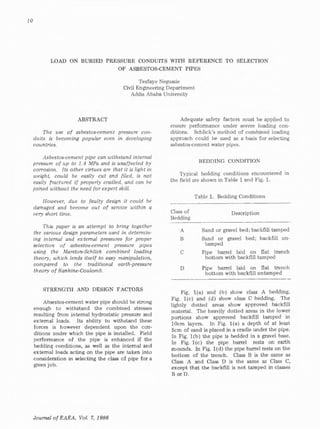
Table 1. Bedding Conditions
Description
Sand or gravel bed; backfill tamped
Sand or gravel bed; backfill un-
tamped
Pipe barrel laid on flat trench
bottom with backfill tamped
Pipe barrel laid on flat trench
bottom with backfill untamped
Fig. l(a) and (b) show class A bedding.
Fig. l(c) and (d) show class C bedding. The
lightly dott.ed areas show approved backfill
material. The heavily dotted areas in the lower
portions show approved backfill tamped in
lOcm layers. In Fig. l(a) a depth of at least
5cm of sand is placed in a cradle under the pipe.
In Fig. l(b) the pipe is bedded in a gravel base.
In Fig. l(c) the pipe barrel rests on earth
mounds. In Fig. 1(d) the pipe barrel rest.s on the
bottom of the trench. Class B is the same as
Class A and Class D is the same as Class C,
except that the backfill is not tamped in classes
B orD.
2. Load on Asbestos-Cement Pipes 11
.. : .. ..
30e111. min. . .. . : .
... . . . . ~....._,.'-:-+-....,_,.--~--f-'.......;---'-:::-......
' ~ J·. • ' •
(a) ( b)
. .. . . .. . ..
3em. min. . .. .... ..
le) ( d l
Fig.l Bedding Conditions illustrated
COMBINED-LOADING THEORY
When asbestos-cement pipe is tested under
various combinations of internal pressure and
exterr;.' ~ load by the 3-edge bearing, a relation-
ship between these loads exist.5 at the point of
fracture. This relationship can be represented
by a parabolic curve as shown in Fig. 2. The
equation of the curve in Fig. 2 may be expressed
as
w
where
w
p =
p
(1)
external load per unit length in the
3-edge bearing that will crash the
pipe when no internal pressure
exists (Nim)
intensity of internal pressure that
will burst the pipe when no ex-
ternal load exist.5 (N/m2
)
intensity of internal pressure in
combination with some external
load, w, applied in 3-edge bearing
that will fracture the pipe (N/m 2 )
w external load in 3-edge bearing
which, in combination with some
internal pressure p, will fracture the
pipe (Nim)
THE THREE-EDGE BEARING TES°i'
The three-edge bearing test (Fig. 3) is a
method of testing the crnshing strength of a
conduit. Because the supporting strength of a
conduit in a trench is affected by the bedding
conditions and the lateral pressure acting against
the sides of the conduit, it is necessary to apply
a load factor to the three-edge bearing loads to
simulate field loading conditions. This relation-
ship can be expressed as
(2)
where
PE = external load
Pr three-edge bearing load
L.F. Load Factor
Table 2 shows load factors values to be used
for the bedding conditions shown in Table 1.
In Fig. 3 the value of C, the clear space between
wooden supports is 13mm for ¢ ,;;;;; 300mm .
25mm for <P between 350-600mm; and 50mm
for <P ~ 750mm.
Journal of EAEA, Vol. 7, 1986
3. 12
I
Fig. 2. Load-Pressure Cruve
Table 2. Relationship Between Pipe Size,
Load Factor and Cl~ of Bedding
Pipe Size Load
(mm) Factor
100-300 1.7
350 - 500 1.8
600-900 2.0
100-900 1.5
100- 300 1.3
350- 500 1.4
600-900 1.5
100 - 900 1.1
Class of
Bedding
A
B
c
D
HYDROSTATIC PRESSURES
The internal hydrostatic pressures to be
considered in designing pipelines are normal
operating pressures which are dependent upon
the service condition and water hammer pressure
which arise as a result of sudden closure of a
valve resulting in immediate build of pressure
wave, called surge pressure. A factor of safety
of 4.0 is normally used to cater for the normal
internal hydrostatic pressure and water hammer
pressure. Allowance for water hammer pressure
is given by the equation
Journal of EAEA, Vol. 7, 1986
Tesfaye Negussie
w
Pipe sample
Fig. 3. Crushing Test Assembly (3-edge bearing)
(3)
where
Ph(max) = maximum build-up of water
1 hammer pressure (N/m2
)
up velocity of water wave
vw = velocity of water in conduit just
before pipe closure (m/sec)
The velocity of the pressure wave, v may
be expressed by the equation P
1
where
d
t
(4)
1/.1 density of the water in the conduit
(Kg/m3
)
Ew modulus of elasticity of asbestos-
cement pipe (N/m2 )
d!t ratio of internal diameter to shell
thickness of pipe
In Eq. 4, Ew = 2.06 X 10³
MN/m" and
EA = 2.34 X 10⁴
MN/m2
•
4. Load on Asbestos-Cement Pipes
1.'J
EXTERNAL LOADS
Exremal loads on conduits in trenches or
those surrounded with earth are dead loads due
to backfill and superimposed loads due to static
or moving loads. >1arston 's theory states that
the load on a buried conduit equals the weight
of the backfill material directly over the conduit
plus or minus the frictional or shearing forces
transferred to that prism by the adjacent prisms
of earth. The magnitude and direction of these
frictional forces are functions of the amount of
relative settlement occuring between the interior
and adjacent earth prisms.
After intensive experimentation, Marston
propounded the following set of approximate
equations for computation of external loads.
For pipes on, or projecting above ground in
cohesionless cover material
W = C 'Y D 2 (5)
For flexible pipes in trenches and thoroughly
compacted side fills
W = (C0
- C' h BD (6)
For rigid pipes in trenches, with ordinary
bedding and B < 1.5D
W = (C0
- C') 'Y D2
(7)
In the above equations W is the load of
cover material per unit length of pipe (Nim);
'Y is the unit weight of backfill (N/m3
); B is
the trench width at the top of pipe (m); D is
the external diameter of the conduit (m); C,
C0
, C' are experimental coefficients. The
general forrn of Marston's equation is,
w C'' 'Y B2
(8)
In Eq. 8 the units of the parameters are as
defined above. Any system of unit if applied
consistently could be used with the above
formulae. The coefficients c, CO' c', c" are
dependent upon the ratio of depth of fill to
width of conduit or trench; the shearing forces
on the plane between the backfill and adjacent
earth; for embankment condition, the amounL
of relative settlement between the backfill and
adjacent earth; the rigidity of the conduit
support under embankment loading.
Table 3. Selected values of c'' for use in Eq. 8
Sand and
H/B damp top Saturated
soil top soil
1
2
3
4
5
6
7
8
0.85
1.46
1.90
2.22
2.45
2.61
2.73
2.81
0.86
1.50
1.98
2.33
2.59
2.78
2.93
3.03
Damp Saturated
Clay Clay
0.88
1.56
2.08
2.49
2.80
3.04
3.22
3.37
0.90
1.62
2.20
2.66
3.03
3.33
3.57
3.76
The values of these coefficients may be
determined from Fig. 4.
If a condition occurs where the width of the
trench, B is less than two or three times the
diameter of the conduit, D, then Marston's
formula for trench condition could be used to
determine W.
(9)
Cd, which is a load coefficient may be deter-
mined from Fig. 5 for various values of H/Bd .
When very heavy superimposed or impact
loads are encountered in the field, their
magnitude may be computed on the basis of
either a concentrated load such as wheel load or
on the basis of distributed load. Ordinarily axle
loads and accompanying impact loads are
neglected if the depth of cover is greater than
about 1.80m. Superimposed load produced by
heavy concentrated load (Fig. 6) could be
determined by the formula
= (10)
Journal of EAEA, Vol. 7, 1986
5. 14 Tesfaye Negussie
where
-0
c
-~
0
--Q)
0
0
-0
.,
Q)
::J
0
>
p
F
= superimposed concentrated load
on the conduit (Nim)
concentrated load (N)
impact factor (Table 4)
load coefficient dependent upon
Bc/211 and L/211 (Tables 5 and 6)
Be External diameter or width of
conduit (m)
H = depth of back fill from crown
(top of conduit) to ground surface
(m)
L effective length of conduit (m)
1.0
0.8
0.6
0.5
0.4
o.3
0.2
Fluid fill C0 =5.0
2 3 4 5 6
Table 4. Impact factor caused by moving
vehicles
Type of Traffic
Highway
Railway
Airfields, taxiways,
aprons, etc.
7 8 9 10
Impact Factor, F
II
1.50
1.75
1.25
12
Values of H/B
Fig. 4. Vertical External Loads on Circular Conduits
Journal of EAEA, Vol 7, 1986
6. 'Q
co
':x:
Load on Asbestos-Cement Pipes
40~---~---~-~-~~~~-t---T-----,---,---..,-,,--.--.
A 8 C D E
30 1------+---+--+-~-t--l--t-·+-i------T--t-1-t-tt--t-1
I01----·-+-___,--+--1---+--+-+-+-·+----·---+---+-~1f-l-J)~/--<I I
8 >--------1--·--l-- +---+--+---+--l-+--i- - I I I
-·+-----I---+---+---+·~-+- ~~-·--·-t- ~ I /
6 ///I//
1------+- ·- I I//V
----+--~1---4--- -- f.- - - -- f--·-·-- 11-/.lh.r-'l'..'//'""*- -r--t
: =--=--=------+-------+- --.-1----+----t-·- -+--!-+--+- -----;)~I---+-___,
2 ~- ~
·-:- -..;;~ ~ ·===-==·.-·--···----.---0.8 ,____·------~--~-----~+~9.~~-1-+--
'---·---~-- - - -- -A~ ·- ---- ·-._--_·_·-__--_---~-~---+----<
0.6 "'P' ---- - - -
!--- -·---+-- ~ . --1--- ··--··--·-- -·---+----+-___,
0.4 W' ·- '""+ -·>-- ---·----- 1-----t----1--t
0 3 L#'" ·-+-
0
-+-+- l ------+----+---+----!
. v
0.2/
O.lw;;.____J_ _--L_--L._.1-....1-....1........1-.J.....J_ _ _ _......L_ _-1..._....1....--'
0.1 0.2 0.3 0.4 0.5 0.6 0.8 I 2 3 4 5
COEFFICIENT -Cd
Fig. 5. Graph for determining Cd coefficients
Fig. 6. Concentrated superimposed load
Journal of EAEA, Vol. 7, 1986
1.5
8. Load on A1be1to•Cement Pipes 17
In like manner, a heavy distributed super·
imposed load could be reckoned from the
expression (Fig. 7)
where
p =
F =
=
H =
D andM =
(11)
superimposed distributed load on
the conduit (Nim)
intensity of distributed load
(N/m2
)
impact factor (Table 3)
external diameter or width of
conduit (m)
depth of backfill from crown of
conduit to ground surface (m)
width and length, respectively of
the area over which the distrib·
uted load acts (m)
SAFETY FACTOR
On the basis of the foregoing, a limited
number of nomograms in the frequently used
ranges of pipe sizes and loading conditions are
made for asbestos-cement pipes using a factor
of safety of 4.0 for internal pressures and 2.5
for external loads. Since the probability of
water-hammer pressure occuring simultaneously
with external impact load is very small, pipes
selected from the curve are therefore given a
factor of safety of only 2.5 for resisting
external loads, consisting of backfill load plus
a 5 ton wheel load and impact load.·
NOMOGRAMIC CURVES
The nomograms in Figs. e to 11 are made
for five pipe sizes in the frequently used range
of</> 150mm - </>900mm. The curves may be
used by entering them through the depth of
coyer and bedding condition scales. The scales
are correlated to the 3-edge bearing equivalents
of the design external loads with a factor of
safety of 2.5 where there is an external loading
condition different from that due only to depth
of cover, however, or where conditions warrant
a change in the factor of safety, the equivalent
external load should be determined and the
selection curves entered at the proper value on
the design external load scale.
The application of the curves to design is
shown in the following examples.
Example 1.
A </> 900mm pipe is to operate at a pressure
of 0.9 MN/m2
at a depth of 2.40m. The avail-
able bedding condition is class B. Select the
class of pipe for this job.
Solution
Enter the nomogramic curve for 4> 900mm
pipe at bedding condition for class B and 2.40m
cover. The intersection of the 2.40 cover line
with 0.9 M N/m2
operating pressure line falls
between pipe classes 150 and 200. Hence use
</> 900mm class 200 pipe. The intersection of
the 2.40m cover line with class 200 curve is at
1.1 MN/m2
operating pressure or 4.4 t1 N/m2
design pressure. Therefore, the pressure safety
factor is
4.4
09
= 4.9
with a factor of safety of 2.5 for external loads.
Table 7 shows how w, the design external
load is determined on the basis of the 3-edgr
bearing test for five commonly encountered
pipe sizes and three frequent!~ used cover
depths.
Example 2
A ef> 500mm asbestos-cement pipe; length
2km; shell thickness 5cm; time of closure of
valve, T = 2sec; velocity of water before closure
of valve = 0.9m/sec; backfill depth, H =2.40m
trench width = l.20m; backfill is sandy soil
'Y 15kN/m' bedding condition class A.
Make necessary calculations neglecting normal
pressure in the pipeline.
Solution
Water hammer pressure
1
Journal ofEAEA. Vol. 7, 1986
d
t
9. 18
Tesfaye Negussie
u = J 2.06 x 10⁹
p " 1000
1
Therefore Vp
.... / 2.06 x 10⁶
l 23.4 x 10⁶
1048 m/sec
The critical time, Tc=
2
L =
VP
2 x 2000
1048
3.82 sec
Therefore, time of closure of value, T < Tc
0.5
0.05
Hence, full water-hammer pressure is developed
Ph(max) = I/I up uw = 1000 X 1048 X 0.8
= 0.84 MN/m2
'.xtemal Load
Csing ~Iarston 's general fonnula
Fig. 7.
Journal of EAEA, Vol. 7, 1986
-
"'e
'z
e
:!
"....:!Q.
..c
~
1
0
Therefore C"' = 1.46
Therefore, lr = 1.46 i'. 15 /- (1.20)z
= 31.54 k'. /m
Selection of Pipe
Enter selection pipe for <P 500mm at bedding
condition class A, 2.40m cover. The inter-
section of 2.40m cover line with 0.84 MN/m2
operating pressure line falls exactly on class
150 pipe.
Extend the 2.40m cover line upwards until
it intersects the Design External Load line at
55 kN/m.
Thus, the chosen pipe is capable of handling
55 kN/m with an external load safety factor of
2.5 x 55
31.54
4.36.
Duic;ln Eiternal Load ( k N /m )
I.e or---'iF----'1"'------"11"-----!i~---!i12..__~-12
I 5 t---t----11----l-----l--~1------l6.0
1.2 4.8
"'E
'z
E
~
3-6
:!
:>
...•d:
c
0.6 2.4 ~
.•0
03 I 2
: A t--o._.r.1.....__.L!I0.___2...._.40_ _:s..._6o:___•.:...=o~~
0
i B o.r.1 1.50 240 3.60 • eo 600
s 1--.L-_.____.._ ___.1...,__~..:... - 1
!' C l---0......r.1~__._ 2f> -
;;
..~ 0.___0.~75_ __..1. _0_ _2~.4_0_ ___:3L~0.:__ __:4L8~0---=&w
Depl!I of Cover , ( m )
10. 986l 'f, 'lOA 'ygyg Jo zvu.mor
0
Beddln9 Co""dition 1
0 (') CD l> 0
0.750.75
075
075
1.50
1.50
1.50
l50
0 2.40
. 2'40~
~ 7
..... 2·40
360
<!ti ~
(0 2.4 3.60 4.80
n
0
<
3·60 4.80 600
~
3 3.60 4.80
6-00
4.80
6°00
0
6l
N "' •
N
• "' a.
Oe119n Pru1ure ( mN I m2
Opero llnQ Pressure , ( mN I m2 l
0 p 0 .-
... "' "' n
0
....
N "'
N • Ill
OulQn Preuure ( mN /m 2
(II
"'0
_...
"'
..0
...0
~
8
ii
0
0
•..C>
:>
0
•..C>
",.,
!
•
"e
r
0
D
~
..z
.....
3
.....;
~
:>
Q
r
0
Q
"
..z
.....
3
11. 20
......,.. c...,,....
0 0 m > 0
o.~
l.l!O
1.50
0 1.40
• ...."Zj ;
~· ~
MO
~ 2.4 ~ ..0 0
0
c
.80 600
!: ~MIO
ii
0
Beddln9 Condi!iO/ls
0 () CD )> 0
075 0.75
0.7!1
075
1.50
1.50
1.50
0
2.40..., 150
;
2.40
"Zj
..... ~ 2.40 3.60
qct
~
0
0
360 4.BO
~
<
240• 3-60~
6-00
3
80
480 6.00
6.on
0
Journal of EAEA, Vol 7, 1986
9
...
9
"'
:-
"'
Te1faye NeguBBie
0-•tl•t
p
•
Operotin9
p
°'
"'•Oul 9n
~-re, (MN IM
2
)
p
..•
... ... .Pr..eure ( 111N '"'
2
Pressure, (mNlm2 )
9 ;.,fl)
(')
li
•..
"'0
0
!" •°' a.
Pr111ur1 (mN I m 2 )
CJI
°'0
(JI
°'0
;
0
~
i;;
0
a.
0
g
'°0
~
g
!!,...,
"'
0
•!!.
'"'~
•..2
!.
r-
•••
..z
'3
0
•.•..,.
~
!:
..!.
r-
0
••
...z
'3
12. Load on Asbestos-Cement Pipes
Table 7(a). Determination ofdesign external load (w) applied in th~ge bearing
1
Pipe
SiZll
(mm)
150
250
300
500
900
150
250
300
500
900
150
250
300
500
900
2
External
Load
{N)
3
Equivalent
3·Edge Beanng
(N)
(Col. 1) I L.F.
CLASS A BEDDING 0.75m
1321 778
2002 1174
2255 1326
2980 1655
4341 2171
4
External Load Applied in
3·Edge Bearing
{N)
(Col. 3 X F.S. of 2.5)
COVER
1945
2935
3315
4138
5428
CLASS A BEDDING l.50m COVER
2820 1659 4150
4501 2647 6618
5222 3074 7685
7912 4397 10993
11351 5676 14190
CLASS A BEDDING 2.40m COVER
4630 2722 6805
7508 4417 11043
8785 5169 12923
12063 6699 16748
17748 8874 22185
Table 7(b). Determination of design sternal load (w) applied in thr~dge bearing
1 2 3 4
Pipe External Equivalent External Load Applied in
Size Load 3-Edge Bearing 3-Edge Bearing
(mm) {N) (N) (N)
(Col. 1) I L.F. (Col. 3 X F.S. of 2.5)
CLASS B BEDDING 0.75m COVER
150 1321 881 2203
250 2002 1334 3335
300 2255 1503 3758
500 2980 1988 4970
900 4341 2896 7240
CLASS B BEDDING l.50m COVER
150 2820 1882 4705
250 4501 2988 7470
300 5222 3483 8722
500 7912 5275 13188
900 11351 7566 18915
CLASS B BENDDING 2.40m COVER
150 4630 3087 7718
250 7608 5008 12520
300 8785 5858 14645
500 12063 8042 20105
900 17748 11832 29580
21
Journal ofEAEA, Vol. 7, 1986
13. 22 Tesfaye Negussie
Table 7(c). Determination of design external load (w) applied in three-edge bearing Table 7(d). DetenninAtion of desil!JI extemal load (w) applied in three-edge bearina
2 8 4
Pipe External Equivalent External Load Applied in
Size Load 8-Edge Bearing 3-Edge Bearing
(mm) (N) (N) (N)
150
260
300
500
900
150
250
300
500
900
150
250
300
500
900
(Col. 2) I L.F. (Col. 3 x F.S. of 2.5)
CLASS C BEDDING 0.75m COVER
1321 1014 2535
2002 1539 3848
2255 1734 4335
2980 2130 5325
4341 2896 2740
CLASS C BEDD1NG l.50m COVER
2820 2171 5428
4501 3461 8643
5222 4017 10043
7912 5649 14123
11351 7566 18915
CLASS C BEDD1NG 2.40m COVER
4.630 3563 8908
7508 5758 14445
8785 6757 16893
12063 8617 21543
17748 11832 29580
BIBLIOGRAPHY
1. Marston, A. "The Theory of External
Loads on Closed Conduits in the Light of
the Latest Experiments". Bulletin No. 96,
Iowa Eng. Experiment Station, Ames,
Iowa, 1930.
2. SP.angler, M.G. "Undergound Conduits -
ki Appraisal of Modem Research". Paper
No. 2337, ASCE Transaction, Vol. 113,
pp. 316-374, 1947.
3. Schlick, W.J. "Supporting Strengths for
Cast. Iron Pipe for Water and Gas Service".
Bulletin No. 146, Iowa, Eng. Experiment
Station, Ames, Iowa, 1940.
4. Kerr, S.L. "Practical Aspects of Water
Hammer". Journal of the American Water
Works Association, No. 40:699, 1948.
5. Fair, G.M., Geyer, J.C., and Okun, D.A.
"Water and Wastewater Engineering". Vol.
I - Water Supply and Wastewater Removal.
John Wiley And Sons Inc. New York, 1968.
Journal of EAEA, Vol. 7, 1986
Pipe
Size
(mm)
150
250
300
500
900
150
260
300
!500
900
160
2!50
300
500
900
2 3 4
External Equivalent External Load Applied in
Load 3-Edae Bearing 3-Edge Bearing
(N) (kN) (kN)
(Col. 2) I L.F. (Col. 3X F.S. of 2.5)
CLASS D BEDDING 0.75m COVER
1331 1201 3003
2002 1819 4548
2255 2051 5128
2980 2713 6783
4341 3945 9863
CLASS D BEDDING l.50m COVER
2820 2566 6415
4501 4092 10230
5222 4750 11875
7912 7192 17980
11351 10319 25798
CLASS D BEDDlNO 2.40m COVER
4630 4208 10520
7608 6828 17070
8785 7984 19960
12063 10964 27410
17748 16183 40333
6. ASCE, "Design and Construction of
Sanitary and Storm Sewers". Manual of
Engineering Practice No. 37, American
Society of Civil Engineers, New York,
1960.
7. Steel, E.W. "Water Supply and Sewerage".
5th Edition, McGraw-Hill Book Company,
1979.
8. Alemayehu Teferra. "Soil Mechanics".
Faculty of Technology, Addis Ababa, 1981.
9. Lelavsky, S. "Irrigation Engineering".
Vol. II, Chapman and Hall Ltd., New York,
1965.
10. Linsley, R.K. and Franzini, J.B. "Elements
of Hydraulic Engineering". McGraw-Hill
Book Company, New York, 1955.
11. Lambe, T.W., and Whitman, R.V. "Soil
Mechanics". John Wiley and Sons, Inc.,
New York, 1969.