Downloaded 363 times

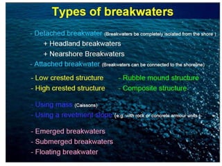

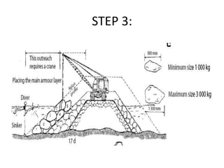
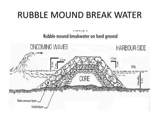
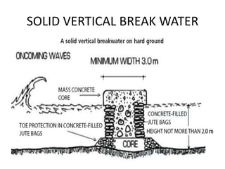
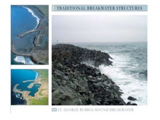


This document provides information on different types of breakwaters, including rubble mound, detached, attached, and solid or vertical breakwaters. It discusses parameters for breakwater construction such as geotechnical investigations, wave hindcasting, and cross-sectional design. Rubble mound breakwaters are made of quarried rock and armor stones and are suitable for shallower depths, while caisson breakwaters can be used in deeper waters. Proper design considers factors like foundation material, water depth, and wave height.


