Compressor
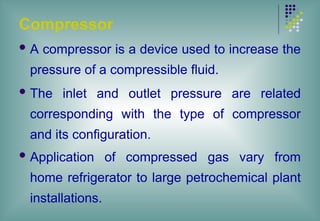
A compressoris a device used to increase the
pressure of a compressible fluid.
The inlet and outlet pressure are related
corresponding with the type of compressor
and its configuration.
Application of compressed gas vary from
home refrigerator to large petrochemical plant
installations.
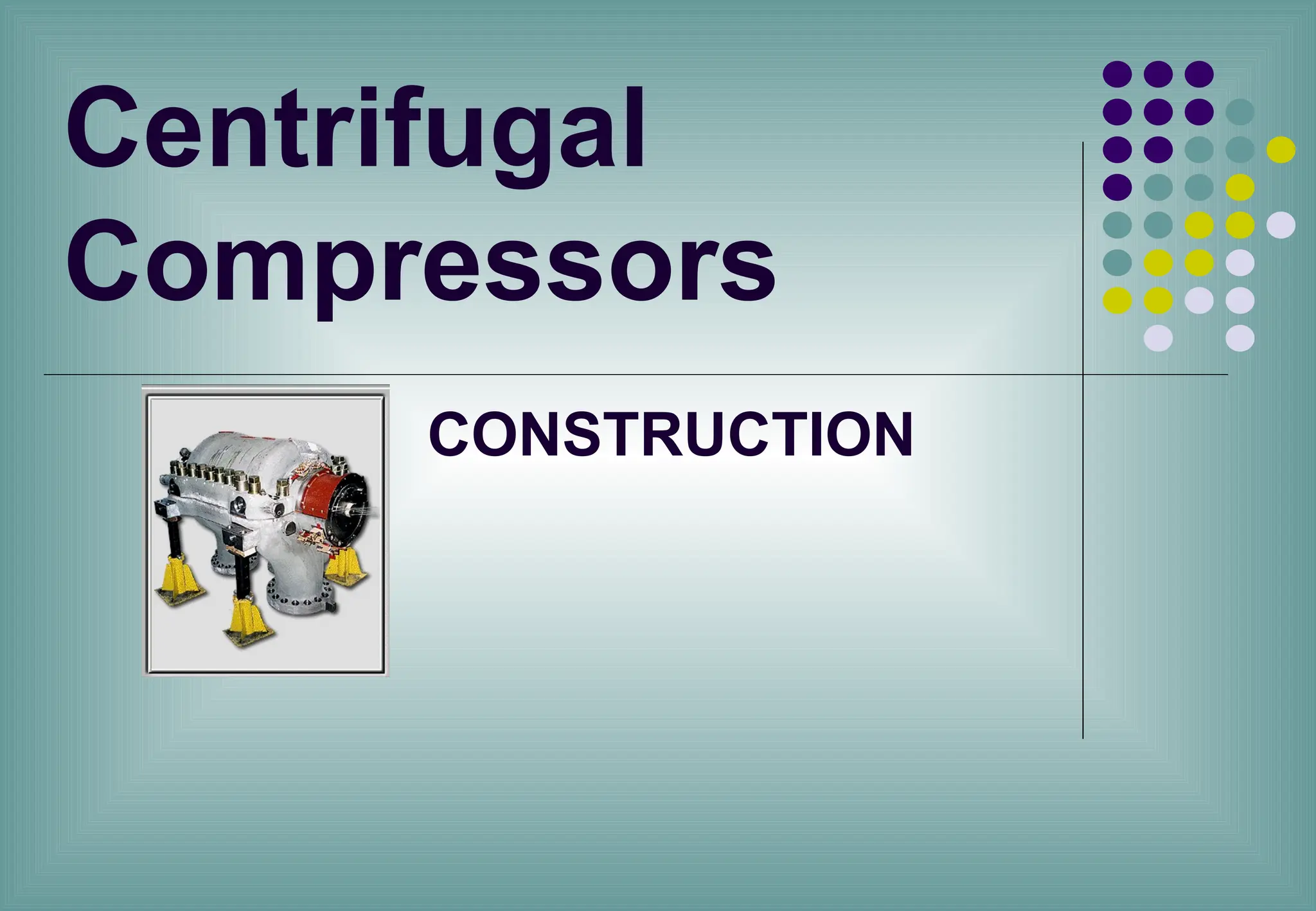
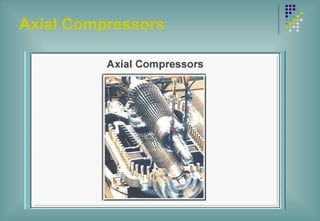
Centrifugal Compressor
CentrifugalCompressor
Dynamic Compressors which are based on
the principle of imparting velocity to a gas
stream and then converting this velocity
energy into pressure energy are termed
as Centrifugal Compressors’.
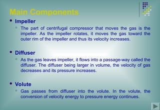
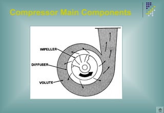
Main Components
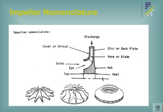
Impeller
The part of centrifugal compressor that moves the gas is the
impeller. As the impeller rotates, it moves the gas toward the
outer rim of the impeller and thus its velocity increases.
Diffuser
As the gas leaves impeller, it flows into a passage-way called the
diffuser. The diffuser being larger in volume, the velocity of gas
decreases and its pressure increases.
Volute
Gas passes from diffuser into the volute. In the volute, the
conversion of velocity energy to pressure energy continues.
8.
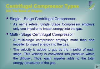
Centrifugal Compressor Types
(OnThe Basis of Stages)
Single - Stage Centrifugal Compressor
As name refers, Single Stage Compressor employs
only one impeller to impart energy into the gas.
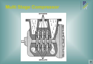
Multi - Stage Centrifugal Compressor
A multi-stage compressor employs more than one
impeller to impart energy into the gas.
The velocity is added to gas by the impeller of each
stage. This velocity is converted into pressure within
the diffuser. Thus, each impeller adds to the total
energy (pressure) of the gas.
9.
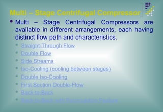
Multi – StageCentrifugal Compressor
Multi – Stage Centrifugal Compressors are
available in different arrangements, each having
distinct flow path and characteristics.
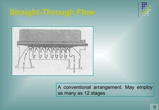
Straight-Through Flow
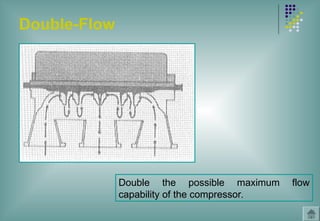
Double Flow
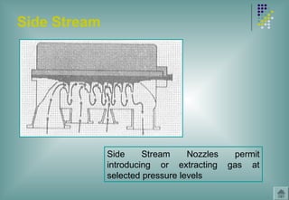
Side Streams
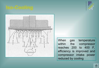
Iso-Cooling (cooling between stages)
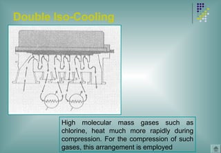
Double Iso-Cooling
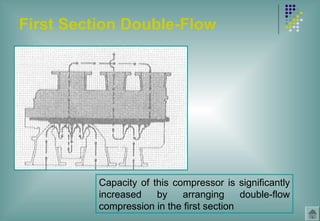
First Section Double-Flow
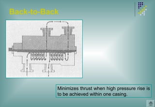
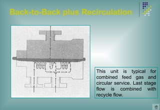
Back-to-Back
Back-to-Back with Recirculation Feature
10.
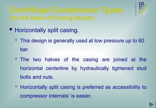
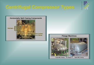
Centrifugal Compressor Types
(Onthe Basis of Casing Design)
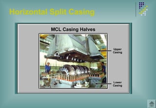
Horizontally split casing.
This design is generally used at low pressure up to 60
bar.
The two halves of the casing are joined at the
horizontal centerline by hydraulically tightened stud
bolts and nuts.
Horizontally split casing is preferred as accessibility to
compressor internals’ is easier.
11.
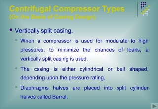
Centrifugal Compressor Types
(Onthe Basis of Casing Design)
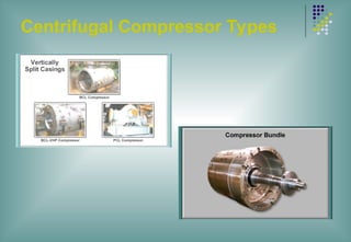
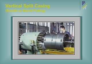
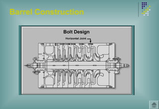
Vertically split casing.
When a compressor is used for moderate to high
pressures, to minimize the chances of leaks, a
vertically split casing is used.
The casing is either cylindrical or bell shaped,
depending upon the pressure rating.
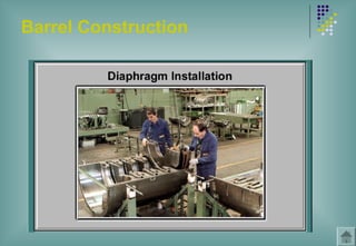
Diaphragms halves are placed into split cylinder
halves called Barrel.
12.
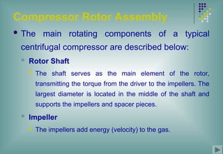
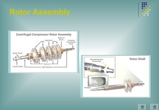
Compressor Rotor Assembly
The main rotating components of a typical
centrifugal compressor are described below:
Rotor Shaft
The shaft serves as the main element of the rotor,
transmitting the torque from the driver to the impellers. The
largest diameter is located in the middle of the shaft and
supports the impellers and spacer pieces.
Impeller
The impellers add energy (velocity) to the gas.
13.
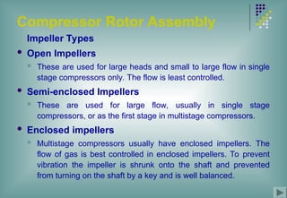
Compressor Rotor Assembly
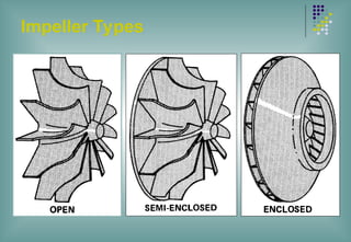
ImpellerTypes
Open Impellers
These are used for large heads and small to large flow in single
stage compressors only. The flow is least controlled.
Semi-enclosed Impellers
These are used for large flow, usually in single stage
compressors, or as the first stage in multistage compressors.
Enclosed impellers
Multistage compressors usually have enclosed impellers. The
flow of gas is best controlled in enclosed impellers. To prevent
vibration the impeller is shrunk onto the shaft and prevented
from turning on the shaft by a key and is well balanced.
14.
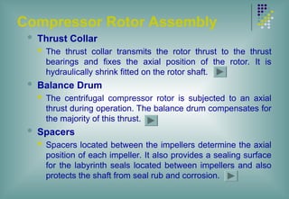
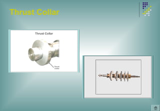
Compressor Rotor Assembly
Thrust Collar
The thrust collar transmits the rotor thrust to the thrust
bearings and fixes the axial position of the rotor. It is
hydraulically shrink fitted on the rotor shaft.
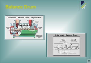
Balance Drum
The centrifugal compressor rotor is subjected to an axial
thrust during operation. The balance drum compensates for
the majority of this thrust.
Spacers
Spacers located between the impellers determine the axial
position of each impeller. It also provides a sealing surface
for the labyrinth seals located between impellers and also
protects the shaft from seal rub and corrosion.
15.
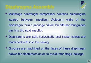
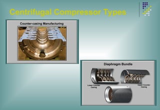
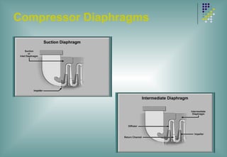
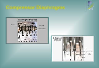
Diaphragms Assembly
Multistagecentrifugal compressor contains diaphragms
located between impellers. Adjacent walls of the
diaphragm form a passage called the diffuser that guides
gas into the next impeller.
Diaphragms are split horizontally and these halves are
machined to fit into the casing.
Grooves are machined on the faces of these diaphragm
halves for elastomers so as to avoid inter stage leakage.
16.
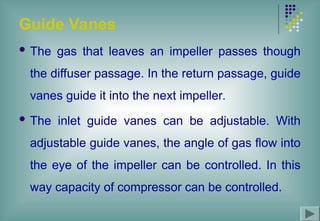
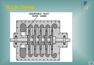
Guide Vanes
Thegas that leaves an impeller passes though
the diffuser passage. In the return passage, guide
vanes guide it into the next impeller.
The inlet guide vanes can be adjustable. With
adjustable guide vanes, the angle of gas flow into
the eye of the impeller can be controlled. In this
way capacity of compressor can be controlled.
17.
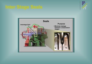
Inter Stage Seals
Rotorshaft passes through the diaphragms.
Since diaphragms and rotor are not attached
to each other, the gas can flow from higher-
pressure region to the lower pressure region
through the space between shaft and
diaphragms. Seals are used between the
shaft and the diaphragms to prevent
leakage. The most common type of seal
used for this purpose is labyrinth seal.
18.
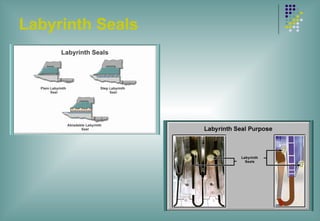
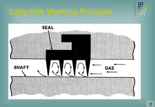
Inter Stage Seals
Labyrinth Seal
It is a set of metal rings or teeth that encircle the shaft
but do not touch it. The rings or teeth are made of soft
metal, and are sharp so that in case of accidental
contact, less friction is generated and shaft is
prevented from damage.
Labyrinth seals are available in the following
configurations:
Plain Labyrinth Seal
Step Labyrinth Seal
Abradable Labyrinth Seal
19.
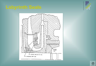
Inter Stage Seals
Labyrinth Working Principle
The spacers between the teeth form
labyrinth passage. As the gas enters the
space between teeth, eddies are formed. It
slows the gas velocity and changes
direction. The resulting turbulence resists
the flow of gas.
20.
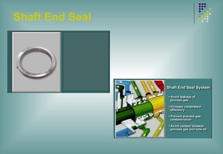
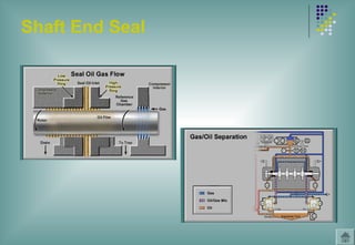
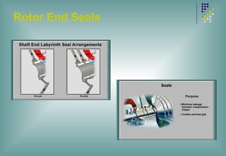
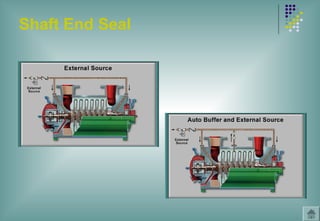
Shaft End Seals
ShaftEnd Seals serve the following three
purposes:
Increase compressor efficiency
Prevent process gas contamination
Avoid contact between the process gas and the
lube oil
21.
Shaft End Seals
Labyrinth Seals
Air, CO2 Compressor FFC-I etc.
Oil Seals
Syn. Gas Compressor FFC-I
Mechanical Seals
Ammonia Compressor FFC-I
Dry Gas Seals
Syn. Gas, Ammonia & CO2 HP Casing FFC-II
22.
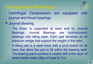
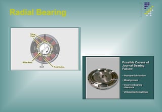
Compressor Bearings
Centrifugal Compressorsare equipped with
journal and thrust bearings.
Journal Bearing
The Rotor is supported at each end by Journal
Bearings. Journal Bearings are hydrodynamic
bearings with tilting pads. Each pad develops an oil
pressure wedge that support the weight of the rotor.
A tilting pad is a steel block with a pivot button on its
back that allow the pad to tilt within the bearing seat.
The bearing pad’s surface is coated with a thin layer of
white babbit metal (alloy of Lead & Tin).
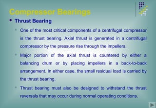
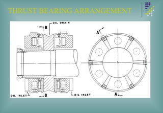
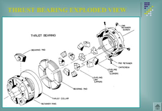
Compressor Bearings
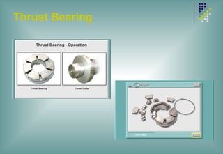
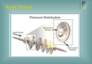
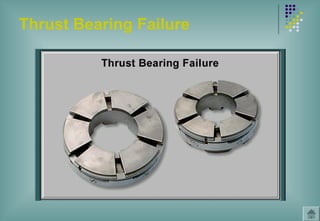
ThrustBearing
One of the most critical components of a centrifugal compressor
is the thrust bearing. Axial thrust is generated in a centrifugal
compressor by the pressure rise through the impellers.
Major portion of the axial thrust is countered by either a
balancing drum or by placing impellers in a back-to-back
arrangement. In either case, the small residual load is carried by
the thrust bearing.
Thrust bearing must also be designed to withstand the thrust
reversals that may occur during normal operating conditions.
25.
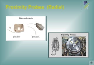
Compressor Instrumentation
Thermocouples
Both Journal and thrust bearing Pads have thermocouples
for temperature monitoring of the bearings pads
Proximity Probes
Radial Vibration Probes are installed to monitor the relative
shaft motion
Axial displacement probes are installed to monitor shaft
axial movement
26.
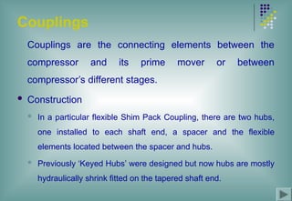
Couplings
Couplings are theconnecting elements between the
compressor and its prime mover or between
compressor’s different stages.
Construction
In a particular flexible Shim Pack Coupling, there are two hubs,
one installed to each shaft end, a spacer and the flexible
elements located between the spacer and hubs.
Previously ‘Keyed Hubs’ were designed but now hubs are mostly
hydraulically shrink fitted on the tapered shaft end.
27.
Couplings
Coupling Functions
Efficient transmission of mechanical power from one
shaft to the other.
To compensate all types of misalignment without
inducing abnormal stresses and load on connected
equipment and without significant loss of power.
To compensate the axial movement of the coupled
shafts, preventing either shaft from exerting excessive
thrust on the other.
28.
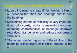
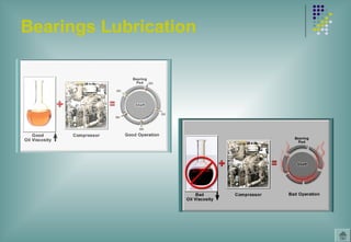
Compressor Lubrication System
Lube oil is used to create lift by forming a film of
oil between the shaft and bearings and to cool
the bearings.
Maintaining correct oil viscosity is very important.
Good oil viscosity works to maintain the correct
operating characteristics of bearings, improves
rotor dynamics behavior and reduces compressor
vibrations.
The same trouble may occur if the oil flow to the
bearings is insufficient or if dirt is present in the
oil.
29.
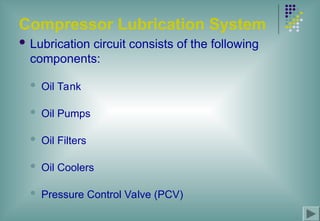
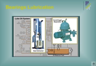
Compressor Lubrication System
Lubrication circuit consists of the following
components:
Oil Tank
Oil Pumps
Oil Filters
Oil Coolers
Pressure Control Valve (PCV)
Double Iso-Cooling
High molecularmass gases such as
chlorine, heat much more rapidly during
compression. For the compression of such
gases, this arrangement is employed


![SBP- Air compressor [Compatibility Mode].pdf](https://cdn.slidesharecdn.com/ss_thumbnails/sbp-aircompressorcompatibilitymode-241227102120-b6a67cde-thumbnail.jpg?width=640&height=640&fit=bounds)


