This document reports on the development of a self-balancing robot. It describes the key modules of the robot's mechanical and electronic systems. The mechanical system uses a wooden structure and two wheels. The electronic system includes a processor module using an Arduino Mega, sensor modules consisting of an IMU and quadrature encoders, actuator modules with DC motors and motor drivers, and a communication module using Zigbee wireless. It then discusses modeling the dynamics of the DC motors and robot, and designing control systems using PID and state space control approaches.

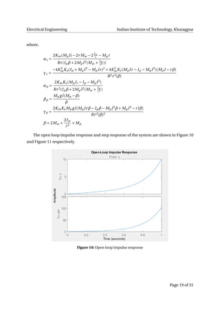
![Electrical Engineering Indian Institute of Technology, Kharagpur
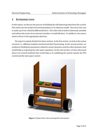
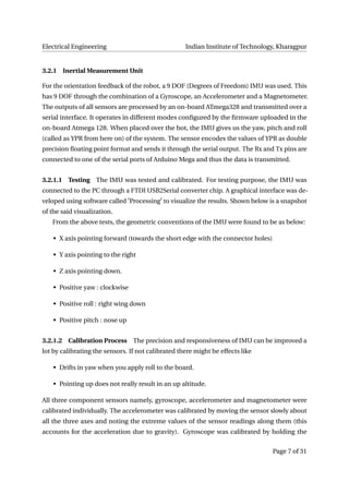
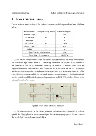
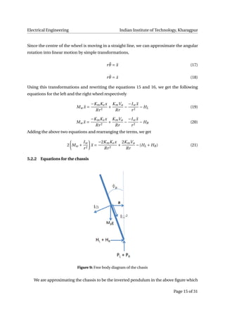
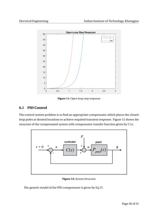
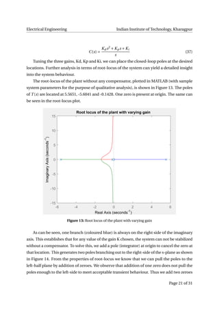
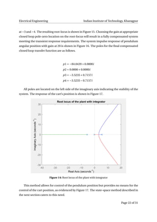
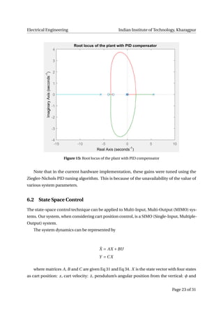
Figure 16: Root locus of the plant with integrator
pendulum’s angular velocity: ˙φ. The outputs of the system are cart position: x and pendulum
angular position from the vertical: φ
The state-space control uses full state feedback. The schematic is shown in Figure 18.
The state-space equations of the above system configuration is given as follows.
˙X = AX +BU = AX +B(−K X +r) = (A −BK )X +Br
˙X = (A −BK )X +Br
Y = C X (38)
where K = [k1k2 ···k3]
The feedback gain vector K can be easily found by representing the system in Phase-
Variable form. The characteristic equation of the system is given by
sn
+ an−1sn−1
+···+ a1s + a0 = 0
The state-space representation of the open-loop system in this form is given by Eq 39.
Page 24 of 31](https://image.slidesharecdn.com/8506ec37-3ce2-4bd5-b771-6863d4c6a1ab-160527062740/85/report_komal-24-320.jpg)
![Electrical Engineering Indian Institute of Technology, Kharagpur
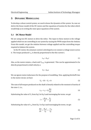
a = (Ip*b + 2*Mp*l^2 * (Mw + Iw/(r^2)));
A = [0 1 0 0;
0 2*Km*Ke*(Mp*l*r−Ip−Mp*(l^2))/R*(r^2)*a (Mp^2*g*l^2)/a 0;
0 0 0 1;
0 2*Km*Ke*(r*b − Mp*l)/R*(r^2)*a (Mp^2*g*l*b)/a 0];
B = [ 0;
2*Km*(Ip + Mp*(l^2) − Mp*l*r)/R*r*a;
0;
2*Km*(Mp*l − r*b)/R*r*a];
C = [1 0 0 0;
0 0 1 0];
D = [0;
0];
s = tf('s');
states = {'x' 'x_dot' 'phi' 'phi_dot'}
inputs = {'u'};
outputs = {'x'; 'phi'};
sys_ss = ss(A, B, C, D, 'statename', states, 'inputname', inputs, 'outputname', outputs)
sys_tf = tf(sys_ss)
%%%%%%%% Impulse response %%%%%%%
% t=0:0.01:1;
% impulse(sys_tf,t);
% title('Open−Loop Impulse Response')
%
% [zeros_1 poles_1] = zpkdata(P_pend, 'v');
% [zeros_2 poles_2] = zpkdata(P_pend, 'v');
%%%%%%%% Step response %%%%%%%
% t = 0:0.05:10;
% u = ones(size(t));
% [y, t] = lsim(sys_tf, u, t);
%
% plot(t, y)
% title('Open−Loop Step Response')
% axis([0 3 0 50])
Page 28 of 31](https://image.slidesharecdn.com/8506ec37-3ce2-4bd5-b771-6863d4c6a1ab-160527062740/85/report_komal-28-320.jpg)
![Electrical Engineering Indian Institute of Technology, Kharagpur
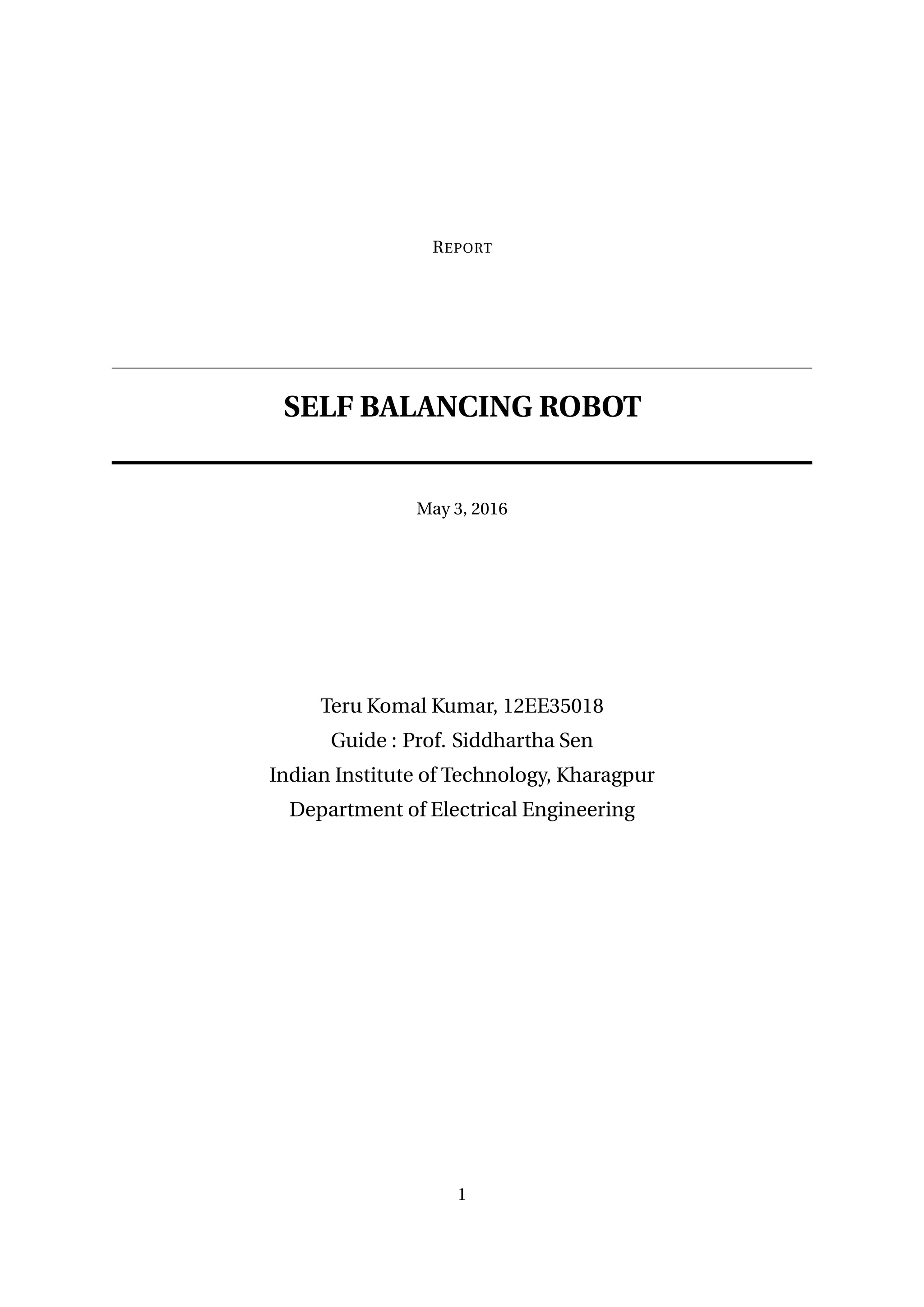
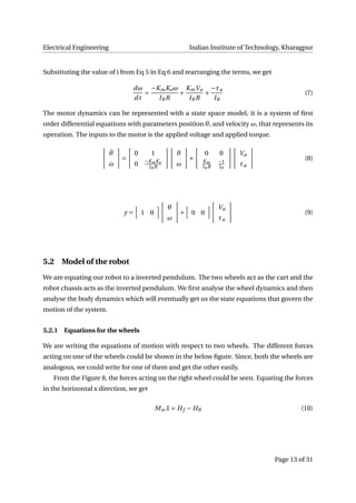
% legend('x', 'phi')
%
% step_info = lsiminfo(y, t);
% cart_info = step_info(1)
% pend_info = step_info(2)
%%%%%%%%% PID Control %%%%%%%%
% Kp = 100;
% Ki = 1;
% Kd = 0;
%
% C = pid(Kp, Ki, Kd);
% T = feedback(P_pend, C);
%
% T2 = feedback(1,P_pend*C)*P_cart;
%
% t=0:0.01:10;
% impulse(T,t)
% title('Response of Pendulum Position to an Impulse Disturbance under PID Control: Kp =
% t = 0:0.01:5;
% impulse(T2, t);
% title('Response of Cart Position to an Impulse Disturbance under PID Control: Kp = 100
%%%%%%% Root locus analysis %%%%%%%
% rlocus(P_pend)
% title('Root locus of the plant with vaying gain')
% C_int = 1/s;
% rlocus(C_int * P_pend)
% title('Root locus of the plant with integrator')
%
% % zeros = zero(C_int * P_pend)
% % poles = pole(C_int * P_pend)
%
% z = [−3 −4];
% p = 0;
% k = 1;
% C_pid = zpk(z, p, k);
% rlocus(C_pid*P_pend)
% title('Root locus of the plant with PID compensator')
Page 29 of 31](https://image.slidesharecdn.com/8506ec37-3ce2-4bd5-b771-6863d4c6a1ab-160527062740/85/report_komal-29-320.jpg)
![Electrical Engineering Indian Institute of Technology, Kharagpur
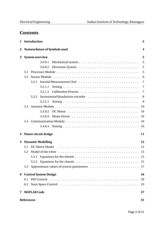
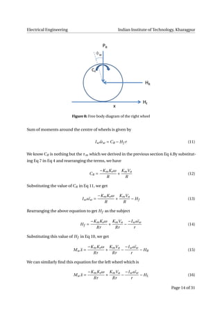
% % %
% [k, target_pole] = rlocfind(C_pid*P_pend)
%
% k = 35;
% T = feedback(P_pend, k*C_pid);
% figure(1)
% impulse(T)
% title('Impulse response of the plant with PID compensator')
%
% T3 = feedback(1,P_pend*C_pid)*P_cart;
% figure(2)
% impulse(T3)
% title('Impulse response of the cart position with PID compensator')
% axis([0 10 −200 200])
%%%%%%% State−space control %%%%%%%
% poles = eig(A)
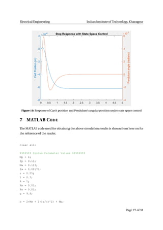
P = [−8.4910 + 7.9283i −8.4910 − 7.9283i −4.7592 + 0.8309i −4.7592 − 0.8309i];
K = place(A, B, P)
Ac = [(A − B*K)];
Bc = [B];
Cc = [C];
Dc = [D];
p = eig(Ac)
states = {'x' 'x_dot' 'phi' 'phi_dot'};
inputs = {'r'};
outputs = {'x' 'phi'};
sys_cl = ss(Ac, Bc, Cc, Dc, 'statename', states, 'inputName', inputs, 'outputName', outp
t = 0:0.01:5;
r = 0.2*ones(size(t));
[y, t, x] = lsim(sys_cl, r, t);
[AX, H1, H2] = plotyy(t, y(:,1), t, y(:, 2), 'plot');
set(get(AX(1), 'Ylabel'), 'String', 'Cart Position (m)');
set(get(AX(2), 'Ylabel'), 'String', 'Pendulum angle (radians)');
title('Step Response with State Space Control')
Page 30 of 31](https://image.slidesharecdn.com/8506ec37-3ce2-4bd5-b771-6863d4c6a1ab-160527062740/85/report_komal-30-320.jpg)
![Electrical Engineering Indian Institute of Technology, Kharagpur
REFERENCES
1. The Control of an Inverted Pendulum,[manual] Available at:<https://engineering.
purdue.edu/AAE/Academics/Courses/aae364L/2011/Fall_2011/lab3/manual>
2. Self-balancing two-wheeled robot,[report] Available at:<http://sebastiannilsson.
com/wp-content/uploads/2013/05/Self-balancing-two-wheeled-robot-report.
pdf>
3. Control Systems Engineering - Norman S. Nise
4. Exploring XBees and XCTU,[manual] Available at:<https://learn.sparkfun.com/
tutorials/exploring-xbees-and-xctu>
5. 9 DOF razor IMU calibration manual,[manual] Available at:<https://github.com/
ptrbrtz/razor-9dof-ahrs/wiki/Tutorial>
6. Arduino tuitorials on www.arduino.cc
Page 31 of 31](https://image.slidesharecdn.com/8506ec37-3ce2-4bd5-b771-6863d4c6a1ab-160527062740/85/report_komal-31-320.jpg)