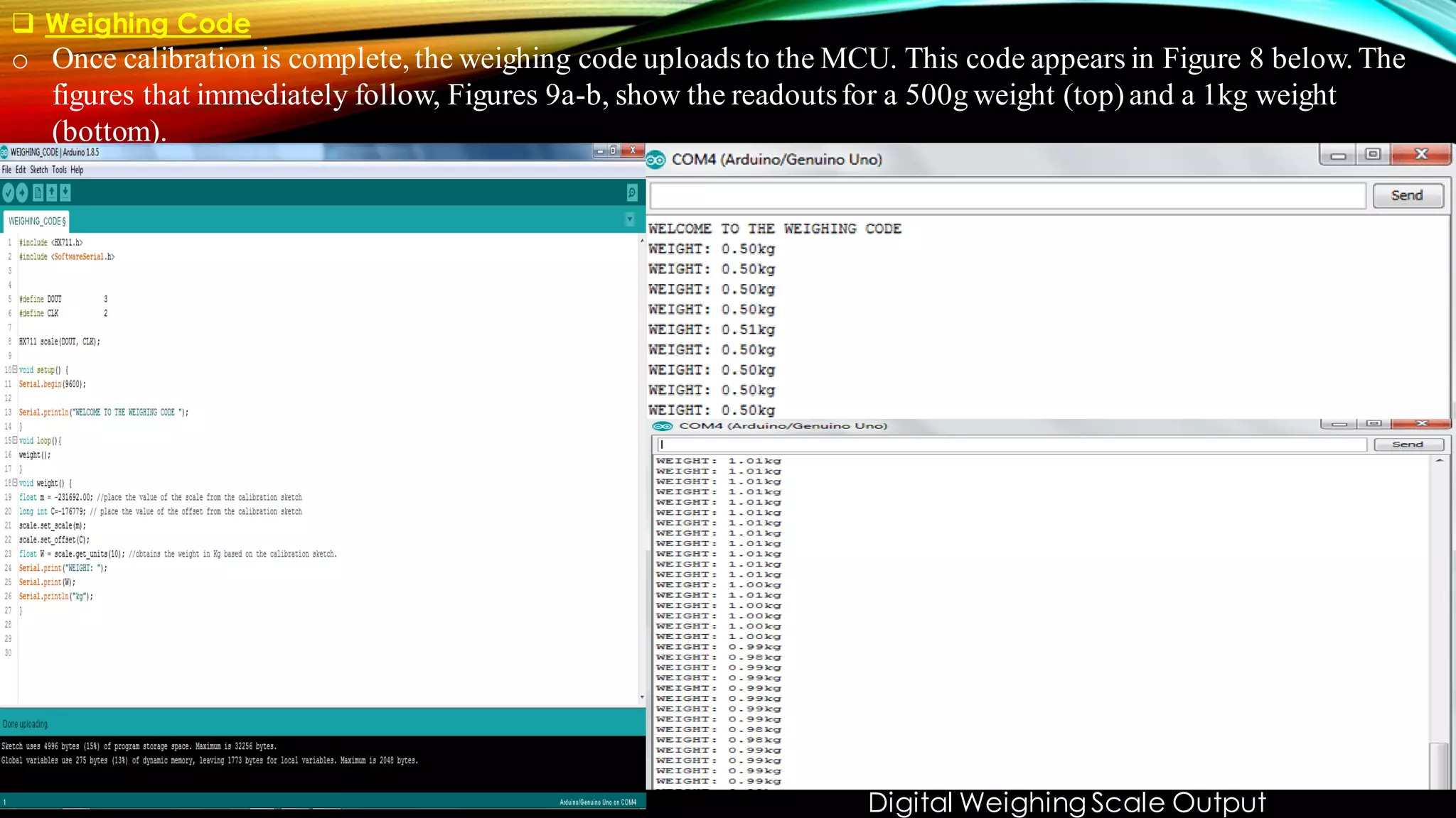
This is the ppt that we made to present our idea of "Inbuilt Weighing System Inside Travel Bag" in techFest'21 at Sant Longowal Institute Of Engineering And Technology (Deemed University), Punjab, India.
The main objective of capstone project is to design and develop a stable flying drone as a model
for general purposes that can be used for deliveries. The drone should be able to support lifting a
phone or similar weight, and some minor modifications should be applied to it. The drone could
be replaced in such a way that would fit any other application. I started the introduction of my
report by defining what a quadcopter is, simply because my drone’s flying system will be in that
form in which a brushless motor will be inserted in each arm. As for the control part, I will be
using a remote controller in which a transmitter will be inserted inside that would communicate
the receiver placed in the drone.
Speed and direction control of dc motor using android mobile application chan...chandan kumar
This project is all about the wireless operation of a DC Motor. In this project, we will control the speed of a DC Motor. Direction of the rotation will also be controlled. Wireless facility is provided with the help of Bluetooth connectivity. An android handset is required to control the operation. As the name suggests that “Speed and Direction Control of DC Motor using Android Mobile Application” is controlling the speed of a DC motor with any mobile phone containing some medium of connectivity such as Bluetooth. Various terms related to this project can be discussed as follows. Since we are concern with the wireless application that is why we are using here a mobile phone to control the whole process. Now the question is why should we use a mobile phone? Which is the most suitable mobile phone? So the answer is that mobile is used only for a Bluetooth connection. We need not to carry an extra device for transmitting the data. This transmitter is already inbuilt in a mobile phone. Now come with the question of most suitable mobile phone, so it can be observed that Android phones are the most widely used phones. Android phones are very easy from the operating point of view. I-phones and windows phones are not as popular as the Android phones. So the Android phone will be used here
working video- https://youtu.be/RPHu4fDcvqM
This document describes a gesture controlled car that can be operated through hand gestures detected by an accelerometer worn on the hand. It consists of an accelerometer, microcontroller, motor driver, motors, RF module, encoder and decoder ICs. The accelerometer senses hand tilts and generates control signals to move the car in four directions. This technology allows for more natural interaction than traditional interfaces and has applications in entertainment, remote control, industrial control, military robotics and medical surgery. Gesture control is expected to become more advanced and widespread with further technological progress.
This was my final year project based on embedded system
this is the code
http://downloads..com/download/24001476/code.rar.html
and the pcb are
http://downloads..com/download/24001498/pcb.rar.html
BLACK BOX INVESTIGATION SYSTEM FOR VEHICLESMriganka Das
As the number of vehicles has grown in a tremendous rate in the last century, the world has become totally dependent on vehicles for the transportation purpose. But due to heavy traffics and improper ways of driving and sometimes accidentally the vehicles also face the problems of accidents causing a large amount of casualties.
This document describes a gesture controlled robot project. The objective is to create a simple and inexpensive robot that can be controlled through gestures. The robot uses an accelerometer sensor to detect hand movements, which are then wirelessly transmitted via radio waves to the robot. The robot receives the signals and moves in the corresponding directions. The system includes a transmitter section with an accelerometer, comparator, and encoder, and a receiver section with a receiver, decoder, and microcontroller that controls motors to move the robot.
This document discusses speed control of a DC motor using pulse width modulation (PWM) technique. PWM controls the speed of a DC fan motor based on temperature readings from a DHT22 temperature sensor. The Arduino microcontroller measures the temperature and humidity using the DHT22 sensor and adjusts the duty cycle of the PWM signal to the motor to control its speed according to the measured temperature levels. By varying the on-off time of the PWM signal, the average power delivered to the motor can be adjusted to control its speed for different temperature ranges.
1.Gesture recognition enables humans to communicate with the machine and interact naturally without any mechanical devices
2.Gestures can originate from any bodily motion or state but commonly originate from the face or hand
3.This project we have tried to control a robot by hand gestures using an accelerometer sensor in conjunction with a MCU and RF link.
WIRELESS GESTURED CONTROLLED ROBOT USING ACCELEROMETERLOKENDAR KUMAR
This document describes a wireless gesture controlled robot that uses an accelerometer. The robot consists of a transmitting device worn on the hand that detects gestures via an accelerometer. The data is encoded and transmitted to a receiving unit connected to a microcontroller and motors. The microcontroller processes the encoded data and controls the motors to move the robot forward, backward, left or right depending on the detected hand gesture. The system allows controlling a robot's movement through wireless hand gestures without physical buttons or controls.
This document describes a human-robot interaction system based on gesture identification. The system uses an accelerometer worn on the hand to detect gestures and transmit the gesture data wirelessly via Zigbee to a PIC microcontroller. The microcontroller then directs a three-wheeled robot to mirror the detected gestures by moving in accordance. The system aims to allow intuitive control of a robot through natural hand gestures without any specialized training.
The document summarizes a project report on a hand gesture controlled robot. It includes an introduction describing the system, block diagrams of the transmitter and receiver modules, descriptions of the main components used including an accelerometer, microcontroller, RF transmitter and receiver. It also describes the methodology for hand motion recognition using gestures, the wireless communication signal methodology, and motion control methodology using an L293D motor driver IC. The result section shows the transmitting and receiving circuits and describes advantages of RF transmission over IR. Future applications of gesture controlled robots include uses in medical, military, construction and industrial fields.
This document describes a project on an accelerometer controlled robot created by five students at the University of Petroleum and Energy Studies. It includes a certificate signed by their supervisor, Dr. Atul Sidola, acknowledging their work on the project. The introduction describes the goal of designing a low-cost robot that can be controlled by hand gestures detected by an accelerometer without the need for complex and expensive remote controls. It then provides details about the three main components of the robot: the accelerometer sensor, microcontroller for processing sensor output and controlling motors, and DC motors. The literature review provides background information on accelerometers, including how they work and common types such as capacitive and piezoelectric models.
Speed and direction control of dc motor using android mobile application grv ...chandan kumar
This project is all about the wireless operation of a DC Motor. In this project, we will control the speed of a DC Motor. Direction of the rotation will also be controlled. Wireless facility is provided with the help of Bluetooth connectivity. An android handset is required to control the operation. As the name suggests that “Speed and Direction Control of DC Motor using Android Mobile Application” is controlling the speed of a DC motor with any mobile phone containing some medium of connectivity such as Bluetooth
This document discusses gesture control robots. It begins by defining a robot and describing different types of robots based on control, including manual, wired, wireless, semi-autonomous, and autonomous. It then discusses controlling robots through gestures, Bluetooth, voice, and text commands. The document focuses on gesture control, explaining that it allows for natural human-machine interaction. It describes transmitting gesture signals using flex sensors, accelerometers, robotic hands, and image processing. It also covers receiving the signals and comparing different gesture control systems.
The document provides a summary of a student project on a line follower robot. It includes:
1) An acknowledgement section thanking various professors and advisors for their support and guidance.
2) An index listing the sections of the project report, including the introduction, sensors, microcontroller, motor driver, source code, and conclusions.
3) A brief introduction explaining what a line follower robot is and the basic components used in the project, including infrared sensors, a microcontroller, and a motor driver.
The document describes a group project to design a light sensing robotic vehicle using a PIC18F4520 microcontroller board, stepper motors, sensors, and switches. The task is for the robot to search for a light source within a bounded area, stop within 15cm of the light, and re-negotiate its path when obstacles are encountered. The group divided responsibilities and spent four weeks implementing the hardware, writing software, and integrating everything onto the robotic platform. By the end of the project, the light sensing robot was able to follow light, avoid boundaries, react to obstacles, and stop at the desired distance from the light source, as demonstrated in videos of its operation.
This document describes a security-based handheld control bot that uses gesture recognition technology. A camera captures the user's hand gestures which are processed through predefined algorithms in MATLAB to identify the gestures. If a gesture like "forward" is detected, a signal is sent wirelessly to a microcontroller that controls motors on the bot to move forward. This type of gesture-based human-machine interface has applications in assisting disabled individuals and enhancing security and gaming.
This document describes an 8051-based gesture controlled wheel robot. It consists of an accelerometer to sense hand movements as input, an LM324 comparator to convert analog sensor data to digital, an HT12E encoder to transmit data via RF, and an HT12D decoder and 8051 microcontroller in the receiver section to control a motor driver and wheels based on received gestures. Applications include operating robots remotely for military, medical, industrial, and accessibility purposes.
The document describes a final year project report on a gesture controlled car. It includes an introduction describing gesture recognition technology and the components used in the project. The main chapters provide detailed descriptions of the accelerometer, encoder, decoder, microcontroller, motors, and connection diagrams. The implementation chapter explains how the accelerometer outputs analog voltages corresponding to hand movements, which are converted to digital signals and transmitted to control the car.
This document provides an overview of an accelerometer-based gesture control robot project. It introduces the motivation to control devices through gestures instead of buttons. It describes the main components used: an accelerometer sensor to detect hand motions, a microcontroller development board with an ATmega32 chip, and RF modules for wireless signal transmission and reception. The logic used involves transmitting gesture motion signals from the accelerometer to control the robot's movement via a motor driver circuit. Potential applications are in hazardous environments like nuclear plants, military uses, and for human convenience. Further improvements could enhance the accelerometer, use more accurate wireless protocols like ZigBee, and add multiple motion controls.
This document describes the design and functioning of a light following robot. The robot uses light dependent resistors (LDRs) to sense light and an op-amp circuit to compare the light readings from the LDRs. When more light falls on one LDR, the op-amp output activates the corresponding transistor which drives the motor on that side, causing the robot to turn towards the light source. The robot aims to follow a light source such as a flashlight by moving its motors based on the LDR sensor readings processed by the op-amp circuitry. Applications include uses in street lights, alarms, and devices that adjust screen brightness based on ambient lighting.
The document describes the design and development of an autonomous robot named O.S.C.A.R. The robot uses an ATMega328P microcontroller and various sensors to follow a line and detect objects. The main objectives were to assemble the robot hardware including sensors and code the microcontroller firmware. The firmware uses functions, interrupts, timers and ADC to control motors, read sensors and detect light levels to enable autonomous line following and object detection capabilities. Diagrams of the system block, subsystems and code flow are provided along with explanations of the hardware schematic and functional code implementation.
The document describes a hand gesture controlled robot that uses a hand glove with an MPU-6050 gyroscope/accelerometer sensor and Arduino board to wirelessly control a receiving robot car chassis. The transmitter sends gesture movement data via nRF24L01 modules to the receiver Arduino, which uses the data and an L298N motor driver to control the car's two DC motors. Potential applications include remote control of devices, industrial equipment, military robotics, medical procedures, and construction.
IRJET- Vehicle Black Box System using IoTIRJET Journal
This document describes a vehicle black box system using IoT that records vehicle parameters before and during an accident to help investigate causes. The system uses sensors to monitor the engine temperature, alcohol levels, gas leaks, and proximity to objects. It also uses GPS and internet connectivity to send vehicle details and location to emergency services if an accident occurs. The system is intended to help prevent accidents by monitoring for dangerous conditions and reduce response times in the event of an accident.
ArduinoBased Head GestureControlled Robot UsingWireless CommunicationIJERA Editor
This paper describes the robustness of ardiuno based head movement controlled robot. This robot is controlled using motion sensor which is mounted on the head. In future there is need of robots which can be used to ease the human tasks and interact with the human easily. Our objective is to control the robot using head gesture. Accelerometer is used to detect the direction of head movement. In order to full-fill our requirement a program has been written and executed using a microcontroller system. By observing the results of experimentation our gesture formula is very competent and it’s also enhance the natural way of intelligence and also assembled in a simple hardware circuit.
This document describes a hand gesture controlled wireless land rover. The project uses an accelerometer to detect hand gestures which are transmitted via RF to control motors and move the land rover in four directions. The key components are a microcontroller, accelerometer, encoder, transmitter, receiver, motor driver and motors. Programming is done using AVR studio to flash the microcontroller. Advantages include compact size and wireless control using natural hand gestures. Future enhancements could include onboard controls, image processing for improved sensitivity and gyro sensors.
1. The document describes a student project to build a digital weighing machine using a microcontroller. It includes the components used, descriptions of key parts like the load cell and microcontroller, and the hardware and software design.
2. The students faced challenges in constructing the hardware and interfacing with the sensitive microcontroller. Their design provided weight readings but with a large offset that could be improved.
3. The document concludes the low-cost weighing machine was an interesting learning experience and useful product, though commercial versions are more expensive.
The document describes the design of a multimeter using VHDL. The multimeter will have four modes - voltmeter, ammeter, ohmmeter, and beta calculator. It will use an Altera DE2 board programmed with VHDL code to control the logic and display measurements on LEDs and an LCD. The VHDL code will control the states and registers to manipulate the different modes. Additional circuits including a power supply, integrating amplifier, and resistance circuits will be used to measure voltage, current, resistance, and beta. Work has begun on the VHDL code and circuit designs, while future work includes completing the circuit designs and testing the integrated system.
This document describes two devices for measuring water levels in dug wells: a mechanical device and an ultrasonic (SONAR) device.
The mechanical device uses a float attached to the device by a wire to measure depth. As the float sinks and the wire plays out, a sensor counts rotations of a pulley to calculate depth. When the float touches water, a circuit is completed to signal the reading.
The SONAR device uses an ultrasonic sensor to measure distance to the water surface by emitting a pulse and measuring the echo return time. The sensor's range is increased using a parabolic reflector to concentrate the acoustic beam. Both devices aim to be low-cost, portable, and battery-powered for
IRJET- Signal Conditioning Card for Load CellIRJET Journal
This document describes a signal conditioning card designed for load cells. The card amplifies, filters, and converts the low-level millivolt output signal from the load cell into a digital signal that can be read by a programmable logic controller (PLC). Key components of the card include an operational amplifier to maintain excitation voltage to the load cell, an analog-to-digital converter (ADC) to convert the amplified analog signal to a digital signal, and a microcontroller and digital-to-analog converter (DAC) to convert the digital signal back to an analog output suitable for the PLC. The card is designed on a printed circuit board to condition the load cell signal for accurate weight measurement in industrial applications.
Construction of digital voltmeter by Bapi Kumar DasB.k. Das
The document describes the construction of a digital voltmeter. It discusses 6 main sections: 1) a pulse train generator, 2) control and gating circuitry, 3) a counting section, 4) an analog input/transducer, 5) a latching and display section, and 6) completing the connections between all sections. The pulse train generator and control/gating circuitry work together to start and stop counting pulses based on the input voltage. The counting section then counts these pulses. The analog input converts the measured voltage to a signal. This signal is then latched and displayed on the digital readout.
The document describes the design of a digital stopwatch circuit using integrated circuits. The circuit uses a pulse generator to create a 1Hz clock signal, a counter integrated circuit to count the pulses and track seconds and decades, and display driver integrated circuits to show the time on 7-segment displays. With minor modifications, the circuit could be adapted for applications like photo counting, people counting, timers, and alarms. Building the circuit provided learning experiences in pulse generation, troubleshooting circuits, using displays and drivers, and soldering circuits on PCBs.
This document describes a project to design and implement a single-phase smart energy meter capable of detecting power quality events. A group of 4 electrical engineering students developed the meter under faculty guidance. The meter measures supply voltage and current, calculates power parameters, and displays/transmits readings. It uses current and voltage sensors, a microcontroller, and other circuits to acquire data and detect events like voltage variations. The project involved designing sensing circuits, implementing calculations in code, and testing the hardware and software functionality of the smart meter.
IRJET- Arduino Nano based All in One MeterIRJET Journal
This document describes an Arduino Nano-based all-in-one meter device that can measure voltage, current, and power consumption of a load. The circuit uses a voltage sensor and current sensor interfaced with an Arduino Nano microcontroller to measure voltage and current values, which are then used to calculate power consumption in watts. The sensor outputs analog voltage values representing the measured voltage and current, which are read by the Arduino's analog-to-digital converter and processed to display the results on a connected LCD screen. The device provides a low-cost way to measure voltage, current, and power using an Arduino microcontroller.
The document describes designing a circuit to control the brightness of LEDs using a rotary encoder and Arduino. It involves connecting a rotary encoder and 4 LEDs to an Arduino board. An Arduino program is written to read the rotary encoder position and adjust the PWM output to the LEDs, varying their brightness as the encoder is turned. The circuit allows increasing or decreasing the brightness of multiple LEDs simultaneously using a single rotary encoder.
This document describes a monitoring, protection, and control module for a radar transmitter. The module monitors key transmitter parameters, protects the system by triggering faults if parameters exceed thresholds, and controls the transmitter's on/off sequencing. It uses comparators to detect parameter faults, a microcontroller for control and interfacing, an ADC to convert analog signals, and an LCD for output display. The design aims to safely monitor and protect the expensive transmitter components.
The document describes a digital alarm clock circuit designed using the TMS8560 integrated circuit.
The circuit includes components like the TMS8560 and CD4541B ICs, a 3.2768MHz crystal oscillator, 7-segment displays, transistors, resistors, capacitors, and buttons to set the time and alarm. The TMS8560 IC drives the display and generates the alarm signal, while the CD4541B is used as a timer to swap between alarm sounds. The circuit works by allowing the user to set the time and alarm via buttons, which is then driven to the 7-segment display. The alarm signal is amplified to power a buzzer or speaker. Troubleshooting focuses on
Electric Vehicle Charging Method for SmartHomes/Buildings with a Photovoltai...Bharath University
This document presents an electric vehicle charging method for smart homes/buildings with a photovoltaic system. It introduces an algorithm to determine optimal charging schedules for EVs based on predicted PV output and electricity consumption. It also discusses a prototype home energy management system application that provides EV charging schedules according to user preferences. The paper consists of describing the EV charging scheduling algorithm and implementation of the home EMS prototype application.
Overview of the world's first true single-chip wireless power transmitter (IDTP9030), and the world's highest-output-power single-chip receiver solution (IDTP9020). This silicon-based IC solution facilitates the design of wireless power (electromagnetic inductive) charging bases and wirelessly powered battery charging on mobile devices. The highly integrated multi-mode transmitter reduces board footprint by 80 percent and bill-of-materials (BOM) cost by 50 percent compared to existing solutions. Designed to be WPC Qi-compliant, both devices are capable of "multilingual" (multi-mode) operation, supporting both the Qi standard as well as proprietary formats for added features, improved safety, and increased power output capability. Demonstration presented by Jack Deans, Field Applications Manager at IDT. Visit http://www.idt.com/products/power-management/wireless-power.
Training Report on embedded Systems and RoboticsNIT Raipur
Deepak Kumar completed a training report on embedded systems and robotics at I3indya Technologies in Delhi for his vocational project in the 2012-2013 academic year. He studied topics including an overview of embedded systems, microcontrollers like the Atmega16, analog to digital conversion, timers, interfacing various components like 7-segment displays, LCDs, DC motors, sensors, and more. The 3-page report was submitted to his college, the National Institute of Technology Raipur, to fulfill requirements for his Bachelor of Technology degree.
This document describes the design and working of an object counter circuit. The circuit uses an LDR sensor, op-amp, 4510 BCD counter, and 7447 seven segment decoder to count objects passing in front of the LDR. It provides the components, block diagram, circuit diagram, working principle, applications, and cost estimation of the object counter circuit. The circuit is designed to count objects in applications like manufacturing assembly lines, restaurants, banks, and airports.
IRJET- Data Acquisition using Tensile Strength Testing MachineIRJET Journal
This document describes a tensile strength testing machine that was designed to test the strength of textile materials. It discusses the various components of the machine, including the load cell, rotary encoder, microcontroller, analog-to-digital converter (ADC), and other electronic components. The machine is able to automatically record the load and elongation of a specimen as it is placed under increasing tensile stress. The load, elongation, and other data are sent to a computer for analysis. The design of the data acquisition system and electronic components is explained, and the machine is able to accurately measure and record the load-elongation curve of textile specimens during strength testing.
Similar to Inbuilt Digital Weighing System Inside Travel Bag (20)
Build the Next Generation of Apps with the Einstein 1 Platform.
Rejoignez Philippe Ozil pour une session de workshops qui vous guidera à travers les détails de la plateforme Einstein 1, l'importance des données pour la création d'applications d'intelligence artificielle et les différents outils et technologies que Salesforce propose pour vous apporter tous les bénéfices de l'IA.
Redefining brain tumor segmentation: a cutting-edge convolutional neural netw...IJECEIAES
Medical image analysis has witnessed significant advancements with deep learning techniques. In the domain of brain tumor segmentation, the ability to
precisely delineate tumor boundaries from magnetic resonance imaging (MRI)
scans holds profound implications for diagnosis. This study presents an ensemble convolutional neural network (CNN) with transfer learning, integrating
the state-of-the-art Deeplabv3+ architecture with the ResNet18 backbone. The
model is rigorously trained and evaluated, exhibiting remarkable performance
metrics, including an impressive global accuracy of 99.286%, a high-class accuracy of 82.191%, a mean intersection over union (IoU) of 79.900%, a weighted
IoU of 98.620%, and a Boundary F1 (BF) score of 83.303%. Notably, a detailed comparative analysis with existing methods showcases the superiority of
our proposed model. These findings underscore the model’s competence in precise brain tumor localization, underscoring its potential to revolutionize medical
image analysis and enhance healthcare outcomes. This research paves the way
for future exploration and optimization of advanced CNN models in medical
imaging, emphasizing addressing false positives and resource efficiency.
VARIABLE FREQUENCY DRIVE. VFDs are widely used in industrial applications for...PIMR BHOPAL
Variable frequency drive .A Variable Frequency Drive (VFD) is an electronic device used to control the speed and torque of an electric motor by varying the frequency and voltage of its power supply. VFDs are widely used in industrial applications for motor control, providing significant energy savings and precise motor operation.
Null Bangalore | Pentesters Approach to AWS IAMDivyanshu
#Abstract:
- Learn more about the real-world methods for auditing AWS IAM (Identity and Access Management) as a pentester. So let us proceed with a brief discussion of IAM as well as some typical misconfigurations and their potential exploits in order to reinforce the understanding of IAM security best practices.
- Gain actionable insights into AWS IAM policies and roles, using hands on approach.
#Prerequisites:
- Basic understanding of AWS services and architecture
- Familiarity with cloud security concepts
- Experience using the AWS Management Console or AWS CLI.
- For hands on lab create account on [killercoda.com](https://killercoda.com/cloudsecurity-scenario/)
# Scenario Covered:
- Basics of IAM in AWS
- Implementing IAM Policies with Least Privilege to Manage S3 Bucket
- Objective: Create an S3 bucket with least privilege IAM policy and validate access.
- Steps:
- Create S3 bucket.
- Attach least privilege policy to IAM user.
- Validate access.
- Exploiting IAM PassRole Misconfiguration
-Allows a user to pass a specific IAM role to an AWS service (ec2), typically used for service access delegation. Then exploit PassRole Misconfiguration granting unauthorized access to sensitive resources.
- Objective: Demonstrate how a PassRole misconfiguration can grant unauthorized access.
- Steps:
- Allow user to pass IAM role to EC2.
- Exploit misconfiguration for unauthorized access.
- Access sensitive resources.
- Exploiting IAM AssumeRole Misconfiguration with Overly Permissive Role
- An overly permissive IAM role configuration can lead to privilege escalation by creating a role with administrative privileges and allow a user to assume this role.
- Objective: Show how overly permissive IAM roles can lead to privilege escalation.
- Steps:
- Create role with administrative privileges.
- Allow user to assume the role.
- Perform administrative actions.
- Differentiation between PassRole vs AssumeRole
Try at [killercoda.com](https://killercoda.com/cloudsecurity-scenario/)
Applications of artificial Intelligence in Mechanical Engineering.pdfAtif Razi
Historically, mechanical engineering has relied heavily on human expertise and empirical methods to solve complex problems. With the introduction of computer-aided design (CAD) and finite element analysis (FEA), the field took its first steps towards digitization. These tools allowed engineers to simulate and analyze mechanical systems with greater accuracy and efficiency. However, the sheer volume of data generated by modern engineering systems and the increasing complexity of these systems have necessitated more advanced analytical tools, paving the way for AI.
AI offers the capability to process vast amounts of data, identify patterns, and make predictions with a level of speed and accuracy unattainable by traditional methods. This has profound implications for mechanical engineering, enabling more efficient design processes, predictive maintenance strategies, and optimized manufacturing operations. AI-driven tools can learn from historical data, adapt to new information, and continuously improve their performance, making them invaluable in tackling the multifaceted challenges of modern mechanical engineering.
Electric vehicle and photovoltaic advanced roles in enhancing the financial p...IJECEIAES
Climate change's impact on the planet forced the United Nations and governments to promote green energies and electric transportation. The deployments of photovoltaic (PV) and electric vehicle (EV) systems gained stronger momentum due to their numerous advantages over fossil fuel types. The advantages go beyond sustainability to reach financial support and stability. The work in this paper introduces the hybrid system between PV and EV to support industrial and commercial plants. This paper covers the theoretical framework of the proposed hybrid system including the required equation to complete the cost analysis when PV and EV are present. In addition, the proposed design diagram which sets the priorities and requirements of the system is presented. The proposed approach allows setup to advance their power stability, especially during power outages. The presented information supports researchers and plant owners to complete the necessary analysis while promoting the deployment of clean energy. The result of a case study that represents a dairy milk farmer supports the theoretical works and highlights its advanced benefits to existing plants. The short return on investment of the proposed approach supports the paper's novelty approach for the sustainable electrical system. In addition, the proposed system allows for an isolated power setup without the need for a transmission line which enhances the safety of the electrical network
Optimizing Gradle Builds - Gradle DPE Tour Berlin 2024Sinan KOZAK
Sinan from the Delivery Hero mobile infrastructure engineering team shares a deep dive into performance acceleration with Gradle build cache optimizations. Sinan shares their journey into solving complex build-cache problems that affect Gradle builds. By understanding the challenges and solutions found in our journey, we aim to demonstrate the possibilities for faster builds. The case study reveals how overlapping outputs and cache misconfigurations led to significant increases in build times, especially as the project scaled up with numerous modules using Paparazzi tests. The journey from diagnosing to defeating cache issues offers invaluable lessons on maintaining cache integrity without sacrificing functionality.
Use PyCharm for remote debugging of WSL on a Windo cf5c162d672e4e58b4dde5d797...shadow0702a
This document serves as a comprehensive step-by-step guide on how to effectively use PyCharm for remote debugging of the Windows Subsystem for Linux (WSL) on a local Windows machine. It meticulously outlines several critical steps in the process, starting with the crucial task of enabling permissions, followed by the installation and configuration of WSL.
The guide then proceeds to explain how to set up the SSH service within the WSL environment, an integral part of the process. Alongside this, it also provides detailed instructions on how to modify the inbound rules of the Windows firewall to facilitate the process, ensuring that there are no connectivity issues that could potentially hinder the debugging process.
The document further emphasizes on the importance of checking the connection between the Windows and WSL environments, providing instructions on how to ensure that the connection is optimal and ready for remote debugging.
It also offers an in-depth guide on how to configure the WSL interpreter and files within the PyCharm environment. This is essential for ensuring that the debugging process is set up correctly and that the program can be run effectively within the WSL terminal.
Additionally, the document provides guidance on how to set up breakpoints for debugging, a fundamental aspect of the debugging process which allows the developer to stop the execution of their code at certain points and inspect their program at those stages.
Finally, the document concludes by providing a link to a reference blog. This blog offers additional information and guidance on configuring the remote Python interpreter in PyCharm, providing the reader with a well-rounded understanding of the process.
Embedded machine learning-based road conditions and driving behavior monitoringIJECEIAES
Car accident rates have increased in recent years, resulting in losses in human lives, properties, and other financial costs. An embedded machine learning-based system is developed to address this critical issue. The system can monitor road conditions, detect driving patterns, and identify aggressive driving behaviors. The system is based on neural networks trained on a comprehensive dataset of driving events, driving styles, and road conditions. The system effectively detects potential risks and helps mitigate the frequency and impact of accidents. The primary goal is to ensure the safety of drivers and vehicles. Collecting data involved gathering information on three key road events: normal street and normal drive, speed bumps, circular yellow speed bumps, and three aggressive driving actions: sudden start, sudden stop, and sudden entry. The gathered data is processed and analyzed using a machine learning system designed for limited power and memory devices. The developed system resulted in 91.9% accuracy, 93.6% precision, and 92% recall. The achieved inference time on an Arduino Nano 33 BLE Sense with a 32-bit CPU running at 64 MHz is 34 ms and requires 2.6 kB peak RAM and 139.9 kB program flash memory, making it suitable for resource-constrained embedded systems.
1. Inbuilt Weighing device 1.0
for travel bags
• Team Name: Let’s Do It
• Members:-
1. Mohammad Tanveer / 1933530
2. Shubham Mehta / 1933536
3. Harshraj / 1933528
4. Krishna Kumar Yadav / 1933513
5. Azad Ranjan / 1933531
techFest’21
• Sant Longowal Instituteof
EngineeringAnd Technology, Punjab.
• Domain:karyarachna
• Event: Market kshetra
2. Content
1. Introduction
2. Science Behind Measuring System
3. Digital Scale Working
4. Deforming the Strain Gauge
5. Conversion to Electric Energy
6. Pictorial View of How it Look From Inside
7. Trolley Top View How it Look
8. Arduino based weighing system
9. Prices of Both Vendor Based Weighing Scale vs Arduino Based
10. Conclusions
3. INTRODUCTION
❑ Lot of us when travel to airport so thereis a problemof luggage weight measuring so we as a team is
dedicated towards making our world a better place to live through normal concepts. So From where this
idea originated it is originated from the lockdown days because we as a mechanical engineer always
think that how to make a object easy and handy to use. So we have tried to rolled out the
trolley/luggage bag with weight measuring inbuilt 1.0. Overall a good approach has been tried to made
from our side to help shaping our economy better.
❑ The Trolley if its weight is suppose2kg without luggage than with inbuilt measuring system it would be
close to 3kg.
4. SCIENCE BEHIND
MEASUREMENT SYSTEM
❑ How Does a digital weight measuring system weight?
So many of u are knowing or not that through contact force we measure weight of any object many of you
are thinking contact force we want to say the force between the object and the measuring scale.
❑ Whatis the major component behind the digital weighing system?
Strain gauge load cell
5. DIGITAL SCALE WORKING
❑ Digital scales work with the use of a strain gauge load cell. Whereas analog scales use springs to
indicate the weight of an object, digital scales convert the force of a weight to an electric signal. Its key
componentsconsist of a strain gauge, a device used to measure the strain of an object, and load cell
sensor, an electronicdevice used to convert a force into an electrical signal. A load cell is also known as
a force transducer.
❑ When an item is placed on the scale, the weight is first evenly distributed.Under the flat tray of a digital scale you
might find, for example, four slightly raised pegs in the corners that serve to distributethe force of the weight
evenly. The mechanical design of the digital scale then applies the force of the weight to one end of a load cell. As
the weight is applied, that end of the load cell bends downwards.
6. DEFORMING THE STRAIN GAUGE
❑ The force of a weight then deforms the strain gauge. The strain gauge can consist of metal tracks,
or foil, bondedto a printed circuit board or otherbacking. When the metal foil is strained, the
backing flexes or stretches.
7. CONVERSION TO ELECTRIC SIGNAL
❑ The strain gauge then converts the deformation to an electrical signal. Because the load cell has an
electric charge, as it moves downwards, the electrical resistance changes. The resulting small change
in resistance becomes an electrical signal. The signal is run through an analog to digital converter, and
then passes through a microchip that "translates" the data. As a result of this final calculation,numbers
indicating the weight of the object appear on the LCD display of the digital scale.
8. PICTORIAL VIEW OF HOW IT
WILL LOOK FROM THE INSIDE
❑ In the two side of the bottomsurface we put the strain
gauge load cell and there the microchip which act as a
sensor for weight measurement is present after joining
both of them with a lcd both load added up and in the
display we can see. We are making economical so we
are sourcing parts from the vendor who is industrial
standard in weighing system.
❑ Second method by using Arduino we can make but by
this it is not economical and also fragile.
10. ARDUINO BASED WEIGHING SYSTEM
❑ The Signal Conditioner
This is a circuit device that has two functions. It amplifies load cell outputvoltage and filters both its input and
outputsignals. Since the output of the load cell is always very small, measured in mV, this device is critical to
amplify the load cell outputto a usable level. Load cell signal processing requires a special type of amplifier
called the instrumentationamplifier. The filter circuit can be embedded together with the amplifier on a single
chip. This circuit filters noise signals and electromagnetic interference(EMI) that might compromise the load
cell’s amplified signal. It decouplesAC signals from the DC outputsignals. Tacuna Systems offers a signal
conditioningdevice described at this link.
❑ The Microcontroller
This is the central processing unit of the whole digital scale. The analogoutputof the signal conditionerflows to
the analog input port of the microcontroller, which in turn converts this analogsignal to digital. Note that some
signal conditionershave an analog to digital converter circuit together with the amplifier circuit and the filter
circuits on a single chip. This reduces the workload on the microcontroller,as the outputof the signal conditioner
instead goes to the digital input port of the microcontroller. The microcontrollerthen reads the clocked digital
pulses from the conditionerto obtain the data it processes to determine the weight displayed. Finally, the
microcontrollercomputes the weight and then displays it through its connectedLCD screen.
11. ❑ The Liquid Crystal Display
o Coupling These Components
o To build a digital scale yourself, we will use the following components coupled together:
o A 5kg load cell
o An HX711 amplifier
o An Arduino Uno Microcontroller Unit (MCU)
o Any suitable output screen (in this case an Arduino IDE Serial Monitor)
o The physical process to build the digital scale is outlined in the next two steps.
❑ The Hardware Setup
o The 5kg load cell for this project has four wires (some load cells have 5). The wires are as follows, according to the
load cell’s datasheet.
o Red wire is the positive power supply
o White wire is the Ground of the power supply
o Black wire is the positive output
o Green wire is the negative output
o Any extra wire, which might be any color such as blue or yellow, is the ground wire for EMI. It should be connected to the
power supply ground.
o Note the wiring diagram depends on the datasheet of the purchased load cell. Therefore the colors listed above could
match differently (such as green being positive, etc.). Be sure to always request a datasheet from your supplier with your
purchase.
12. ❑ Load Cell to Amplifier Connection
o The wires listed above attach to the appropriate pins of the HX711 amplifier device as shown in the sets of pictures below. The
HX711 is a special amplifier that has 2 channel inputs A and B, each with different amplifier gains adjustable by a computer
program. The channel A has a gain of 128 and 64, while the channel B has a fixed gain of 32.
o Note this HX711 device matches the description of the type of signal conditioning device that has an amplifier, filter, and ADC
embedded together on a single chip. This means its data output goes to the digital input pin of our microcontroller instead of its
analog pin.
Therefore, connectingthe HX711 and the load cell is as followed:
o Red wire/Positive supply -> E+
o White/Negative Supply -> E-
o Green/Negative Ouput -> A-
o Black/Positive Output -> A+
Load Cell to Amplifier
Connections
Amplifier to MCU
Connections
o Amplifier to Microcontroller Connection
o After connecting the amplifier, the next step to build the
digital scale is to connect the microcontroller. The HX711
connects to the Arduino MCU as follows:
o VCC -> 5V supply on Ardunio
o GND ->GND
o CLK -> D2
o DOUT -> D3
13. ❑ The Code
o Once the hardware connectionsare complete, the next step to build the digital scale is to uploadthe program code
to the MCU from a PC through theArduino IDE. The process and the code have two subdivisions: the calibration
code and the weighing code.
❑ Calibration Code
o The calibration codeis the program used to calibratethe load cell transducer. Calibrationconfigures the load cell
outputto always give a precise value of weight and at the particularS.I unit such as Kilograms, Grams, Tons,
Poundsetc.
o The HX711 library code containsa good guide on how to calibratethe load cell.
o The results of the calibration process are shown below in the Serial Monitorof theArduino IDE.
15. ❑ Weighing Code
o Once calibration is complete, the weighing code uploadsto the MCU. This code appears in Figure 8 below. The
figures that immediately follow, Figures 9a-b, show the readoutsfor a 500g weight (top)and a 1kg weight
(bottom).
Digital Weighing Scale Output
16. PRICE OF BOTH VENDOR BASED
WEIGHING SCALE VS ARDUINO BASED
VENDOR BASED
1. ECONOMICAL.
2. NOT UPGRADABLE.
3. CORRECT READING CALIBRATED.
4. NEED ONLY 2 AA BATTERY TO
OPERATE.
5. CONSTRUCTION IS SIMPLE .
6. CHANCES OF ERROR IS NEGLIGIBLE.
7. TROUBLE FREE OPERATION.
8. IF PROBLEM ARISES THAN VENDOR
CAN ONLY OPERATE.
9. OVERALL COST TROLLEY+KIT=3500
WITH 97CM SIZE OF TROLLEY.
ARDUINO BASED
1. NOT ECONOMICAL.
2. UPGRADABLE.
3. CORRECT READING UPTO TO DECIMAL
PLACES.
4. NEED LARGER CELL .
5. CONSTRUCTION IS HARD.
6. ERROR IS MORE.
7. MAY TROUBLE IN FUTURE.
8. IF PROBLEM ARISES IT WILL BE EASY
TO IDENTIFY.
9. OVERALL COST TROLLEY+KIT=5500
WITH 97CM SIZE OF TROLLEY
17. CONCLUSION FOR BOTH VENDOR WEIGHING
SYSTEM AND ARDUINO BASED SYSTEM
o Everything has it pros and cons we are not getting into that for information you all can google and search every
where this type of inbuilt weighing system does not available at all we have tried to implement it in both way
through vendor and through Arduino also in a luggage bag/trolley. The main thing if u focus on this product is that
it just cutoff the dependencyof weight measuring and hence overall improve the user experience. By making this
development we are taking technologies and comfort to the othernew level. This is our first model we are working
on 2.0 for further enhancingthe user experience. Hope in the upcoming year we will immerse as major brand in
luggage industry for creating technological related products.In this we all learnt that nothingis impossible and only
required true dedication.
18. ORGANIZATION STRUCTURE/HOW IT WILL HELP
INDIA
So First of all our brand name as we decided is SWATANTRA LUGGAGE TECHNOLGY it will be exclusive to
onlinestore only we are following b2c in this. We have decided that all 5 of us will head the organization
And we have tied up with VIP bags for supply and currently we are hiring around 10 employs 2 for data
feeding,3 site maintenance,3 assembler and 2 packager additionallywe require other staffs but that is a
matter of time. Now coming to is it make in INDIA off course all major development all thing have been
done in INDIA itself all parts are made in INDIA and we are proud to say that we are helping INDIA for
shaping it economy better by creating jobs and by creating good products we are proud to say we are the
members of let’s do it who have think so far in right direction for completion of the project.
As per part of information but that is not to shared but still our vendor is Hoffen.