1. The document discusses robot trajectory planning, programming languages, and kinematics. It describes different levels of robot programming languages from microprocessor to task-oriented levels.
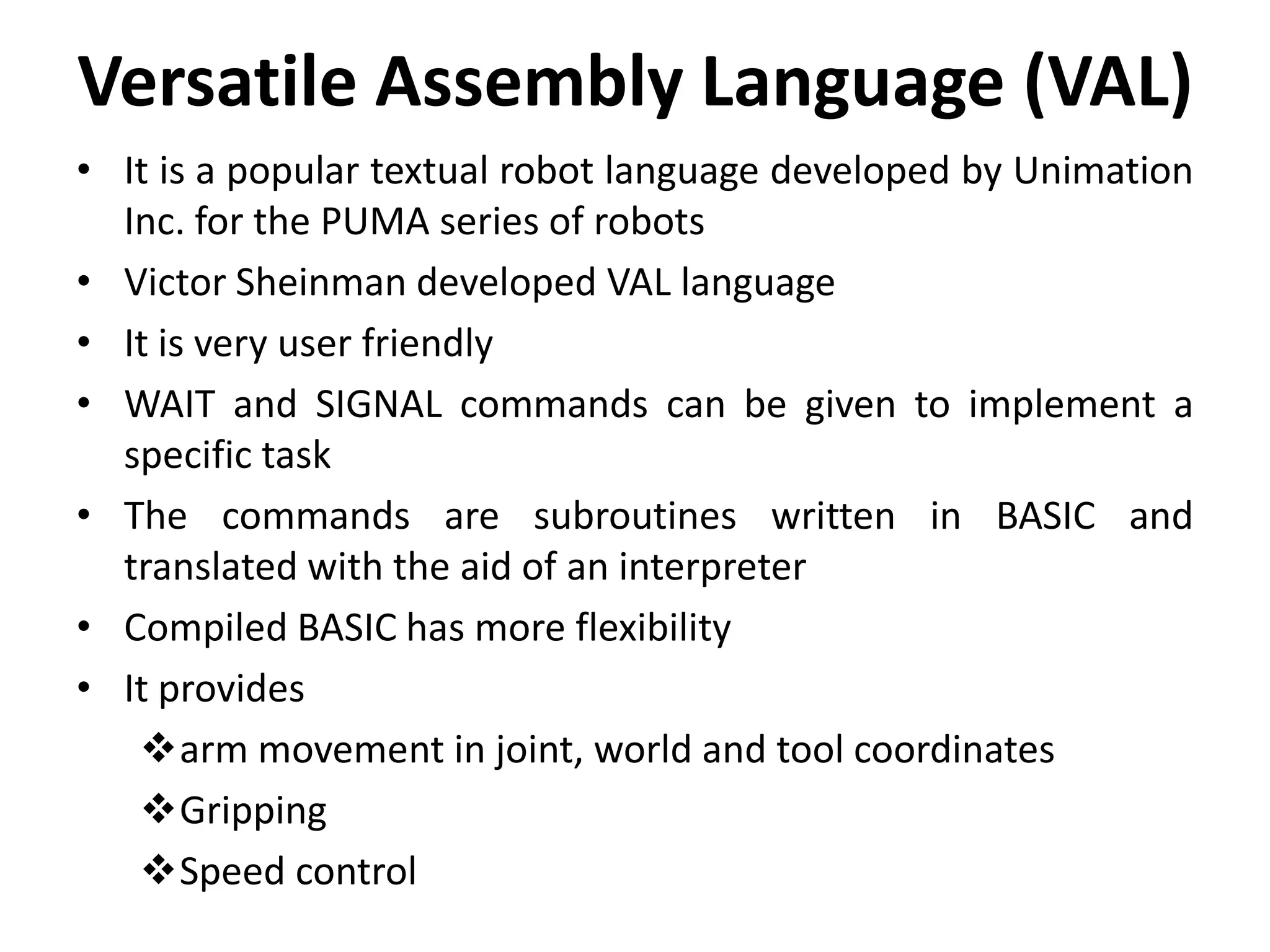
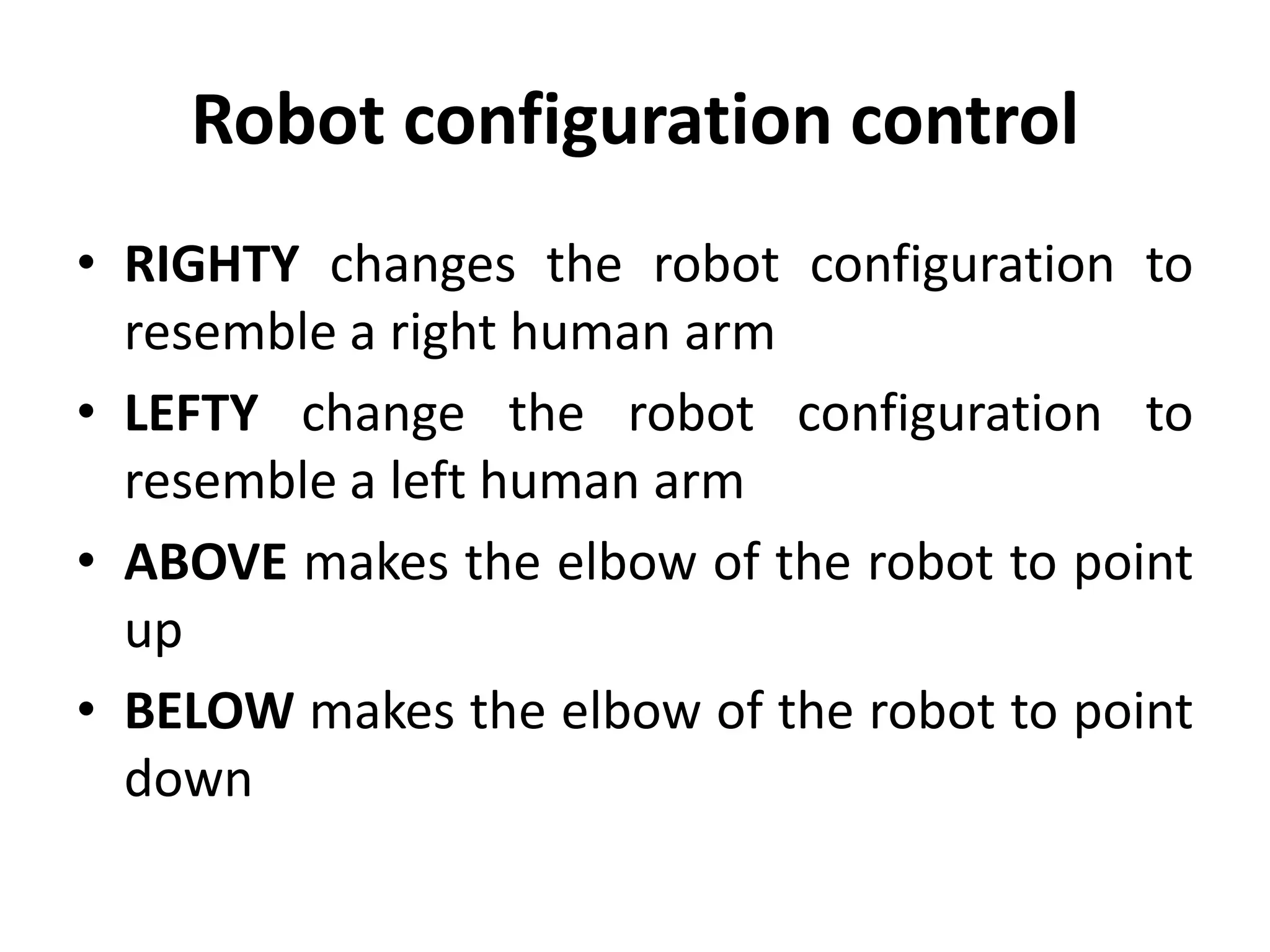
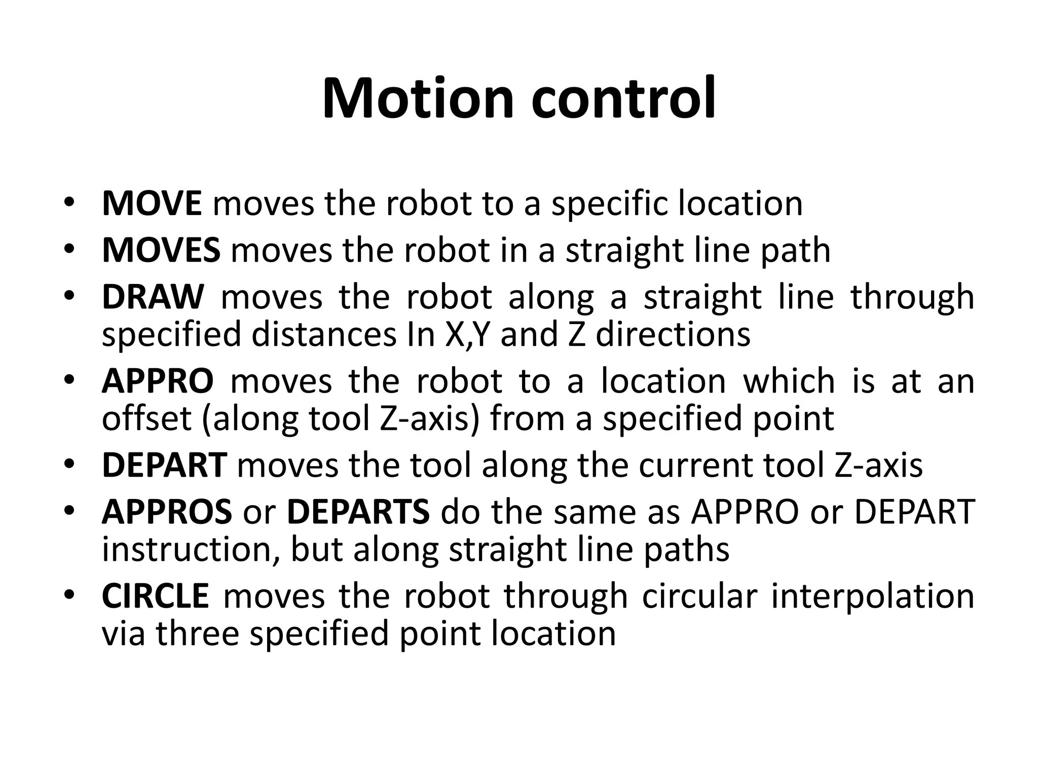
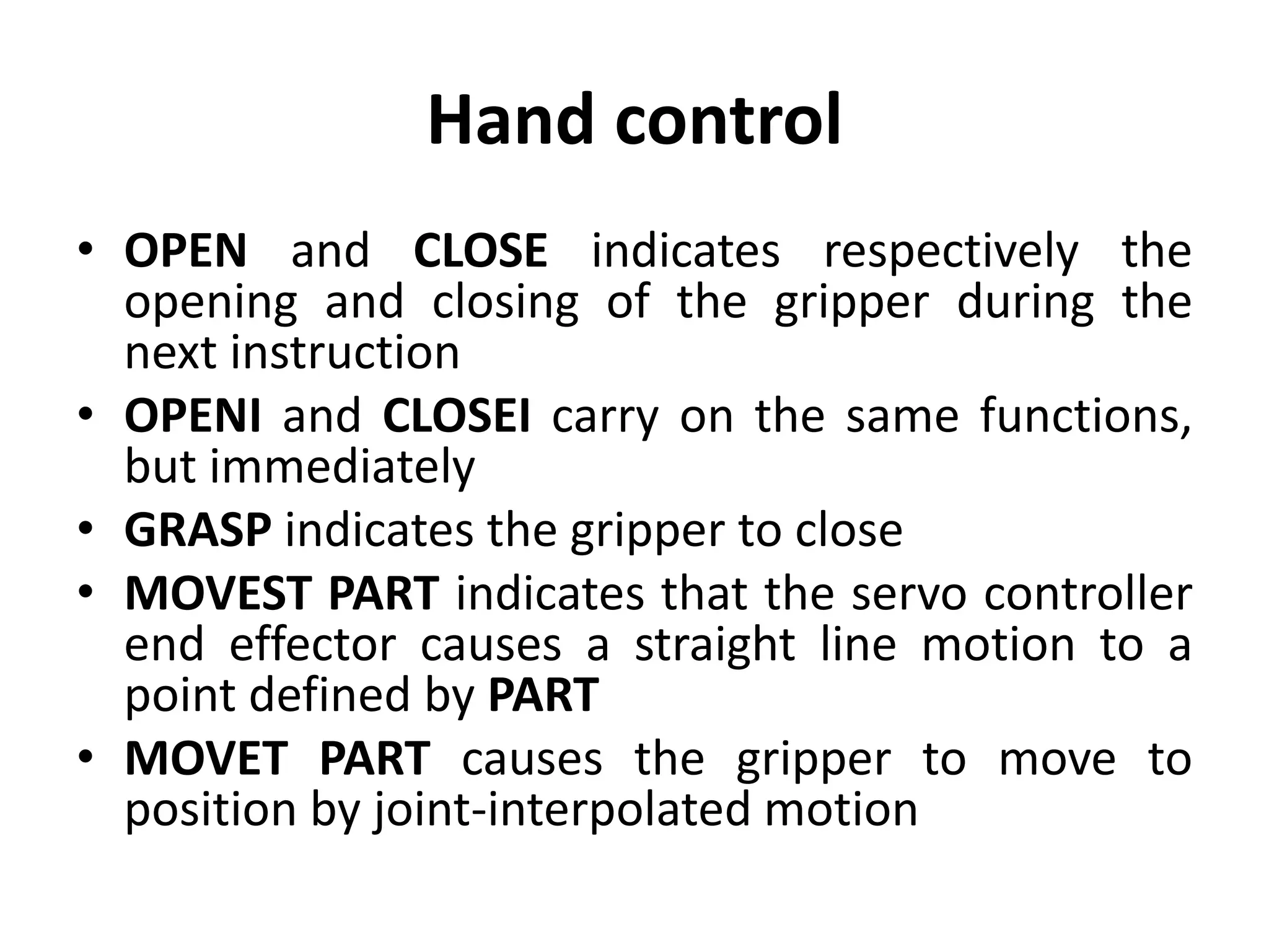
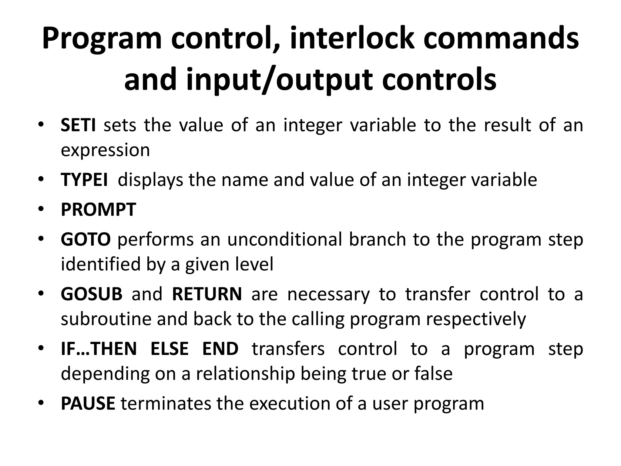
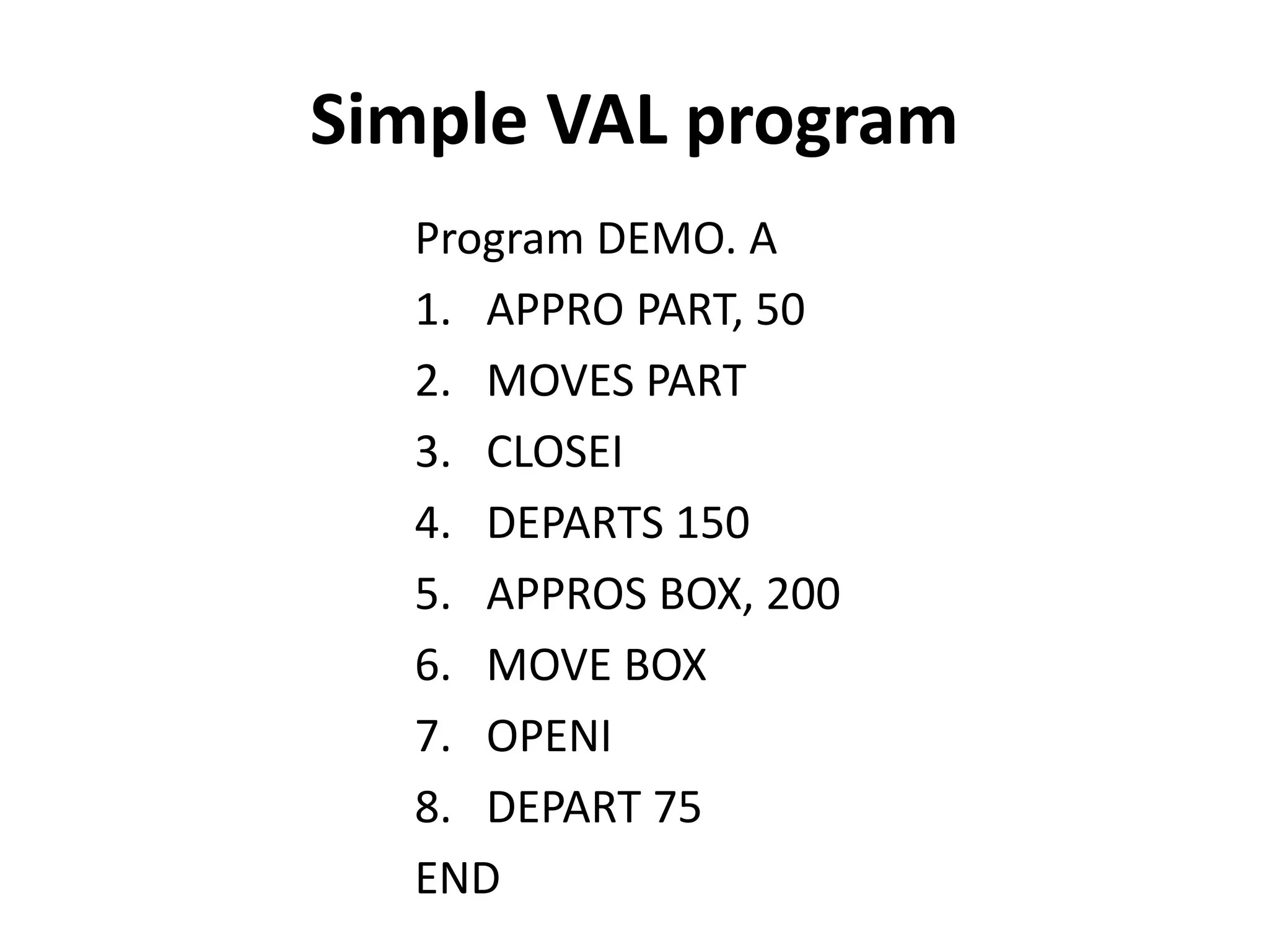
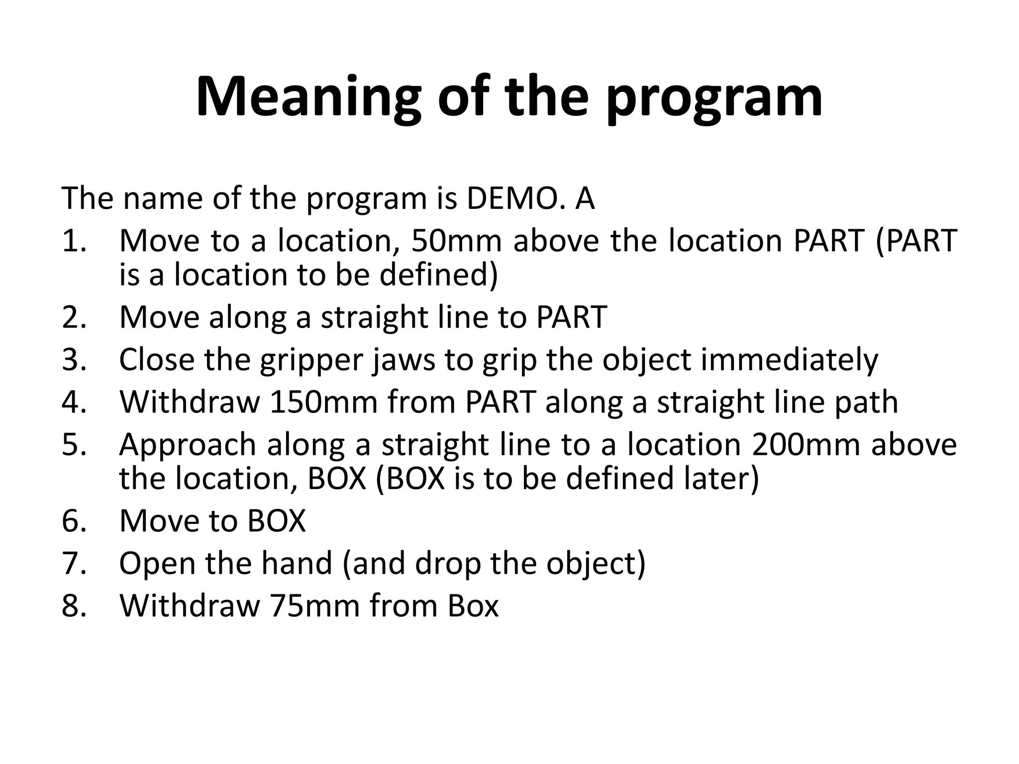
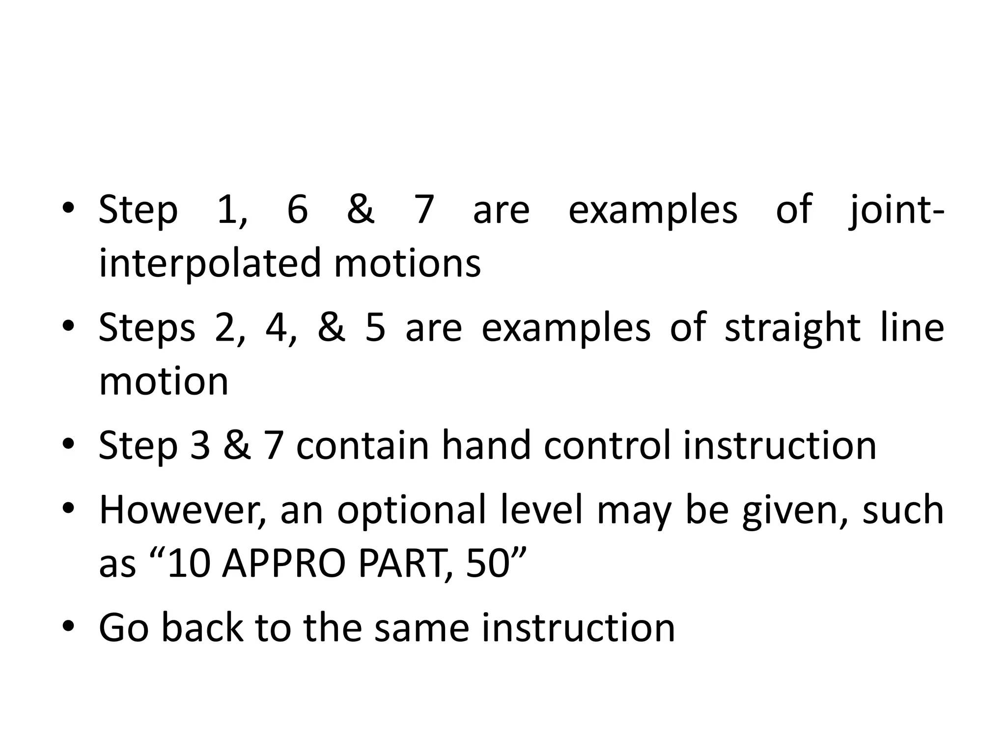
2. Common robot programming languages are described including VAL, a popular language developed for PUMA robots. A simple VAL program example to move grip and transport an object is provided.
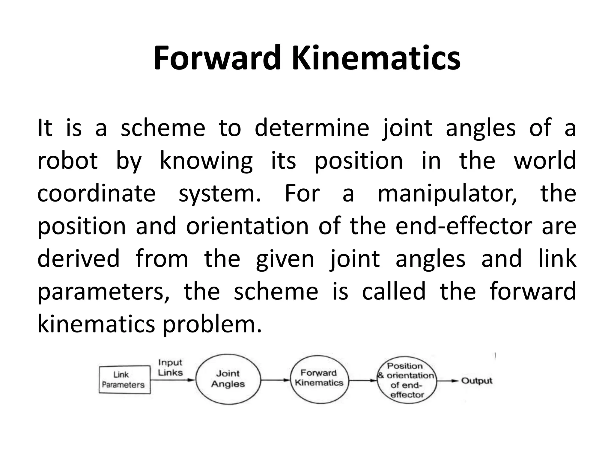
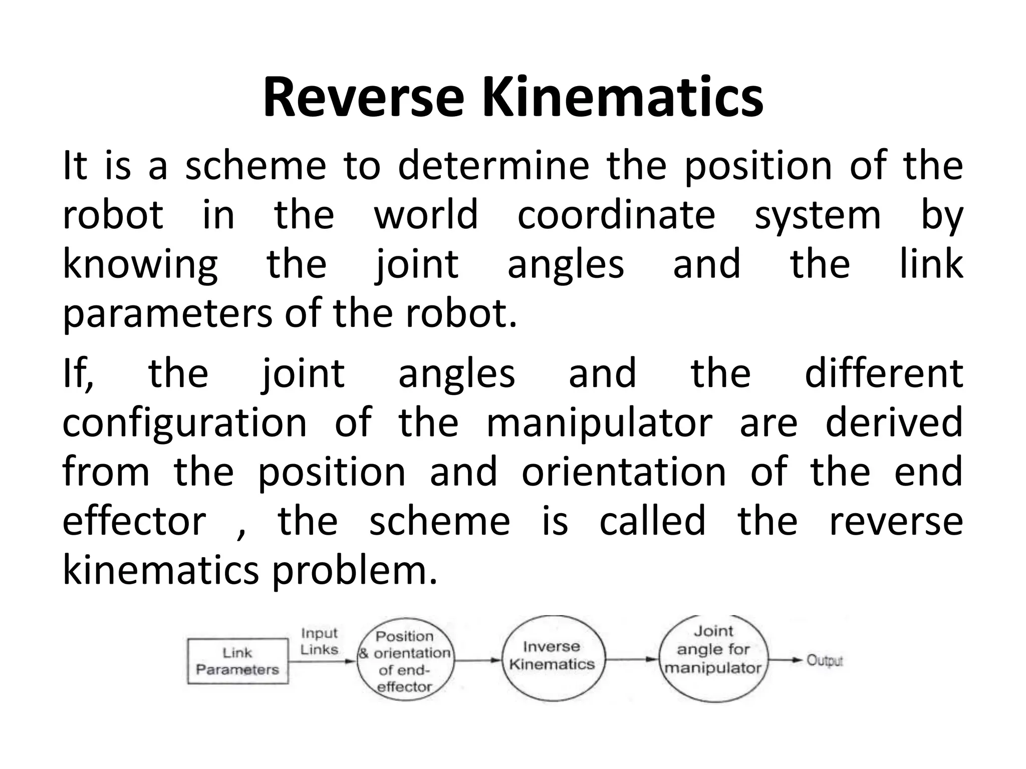
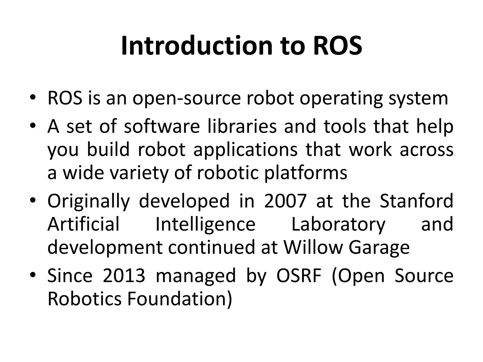
3. Key concepts in robot kinematics like forward and inverse kinematics are explained, which relate joint angles to world coordinates and vice versa. Introduction to the robot operating system ROS is also given.