Downloaded 297 times


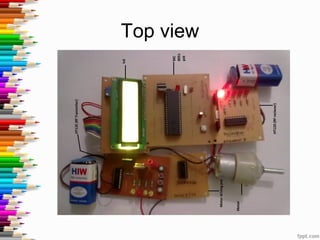


This document presents a project on an RF-based door lock system. The system uses an RF transmitter connected to a keypad to send a password via RF signals to an RF receiver connected to a microcontroller. If the password is correct, the microcontroller activates a relay to unlock the door. If incorrect, an alarm is triggered. The system has applications for securing bank lockers, vehicles, and other devices due to its low cost, wireless operation, and prevention of hacking.