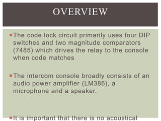
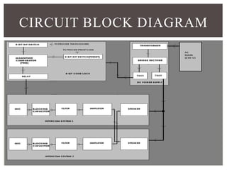
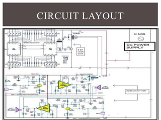
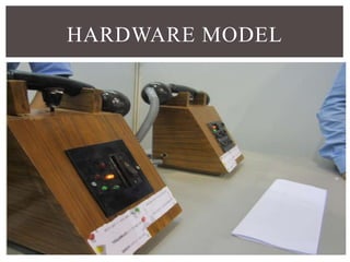
TECHNICAL PAPER 
PRESENTATION 
ON 
8 BIT 
DIGITAL CODE 
LOCK 
INTERCOM 
SYSTEM 
BY 
SAGNIK 
JANA 
E.C.E, 4th
ABSTRACT 
 Intercom system : It primarily comprises of a 
microphone, a speaker and an amplifier. 
The locking circuit provides an 8-bit digital 
code. As soon as the code matches the 
intercom system becomes operational. 
The Intercom system is of a great help for 
intra building communication.
OVERVIEW 
The code lock circuit primarily uses four DIP 
switches and two magnitude comparators 
(7485) which drives the relay to the console 
when code matches 
The intercom console broadly consists of an 
audio power amplifier (LM386), a 
microphone and a speaker. 
 It is important that there is no acoustical
FUNCTIONAL BLOCK 
DIAGRAM
CIRCUIT BLOCK DIAGRAM
OPERATIONAL FLOW CHART 
Dc power supply 
 The 230 volts ac supply is fed to the step down 
transformer which provides a 16 volts ac at its 
output. 
8-bit lock code 
 The password is first set using a preset dip switch 
of 8-bit length & magnitude comparator energizes a 
relay which switches on the intercom system. 
Intercom system 
 The blocking capacitors only allows ac component 
& filters the noise.
CIRCUIT LAYOUT
HARDWARE MODEL
BIBLIOGRAPHY 
 http://www.al ldatasheet.com/datasheet - 
pdf/pdf/8074/NSC/7485.html 
 http://www. researchcel l.com/general/7809-pin-and-circui t - 
diagram/.html 
 http://www.engineersgarage.com/elect ronic-components/7805- 
vol tage- regulator - ic.html 
 http://en.wikipedia.org/wiki/BC548.html 
 http://www.engineersgarage.com/elect ronic-components/ 
t ransistor-bc547-datasheet.html 
 http://www.datasheetarchive.com/IN-4001-datasheet .html 
 http://www. t i .com/product/lm386.html

8 bit digital code lock intercom system

  • 1.
    TECHNICAL PAPER PRESENTATION ON 8 BIT DIGITAL CODE LOCK INTERCOM SYSTEM BY SAGNIK JANA E.C.E, 4th
  • 2.
    ABSTRACT  Intercomsystem : It primarily comprises of a microphone, a speaker and an amplifier. The locking circuit provides an 8-bit digital code. As soon as the code matches the intercom system becomes operational. The Intercom system is of a great help for intra building communication.
  • 3.
    OVERVIEW The codelock circuit primarily uses four DIP switches and two magnitude comparators (7485) which drives the relay to the console when code matches The intercom console broadly consists of an audio power amplifier (LM386), a microphone and a speaker.  It is important that there is no acoustical
  • 4.
  • 5.
  • 6.
    OPERATIONAL FLOW CHART Dc power supply  The 230 volts ac supply is fed to the step down transformer which provides a 16 volts ac at its output. 8-bit lock code  The password is first set using a preset dip switch of 8-bit length & magnitude comparator energizes a relay which switches on the intercom system. Intercom system  The blocking capacitors only allows ac component & filters the noise.
  • 7.
  • 8.
  • 9.
    BIBLIOGRAPHY  http://www.alldatasheet.com/datasheet - pdf/pdf/8074/NSC/7485.html  http://www. researchcel l.com/general/7809-pin-and-circui t - diagram/.html  http://www.engineersgarage.com/elect ronic-components/7805- vol tage- regulator - ic.html  http://en.wikipedia.org/wiki/BC548.html  http://www.engineersgarage.com/elect ronic-components/ t ransistor-bc547-datasheet.html  http://www.datasheetarchive.com/IN-4001-datasheet .html  http://www. t i .com/product/lm386.html