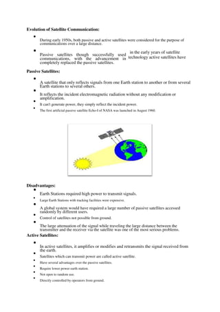
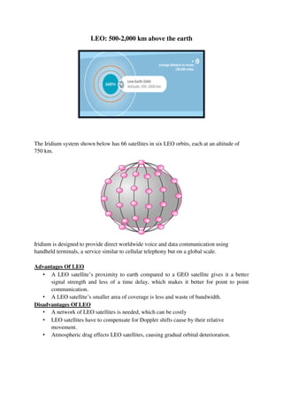
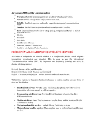
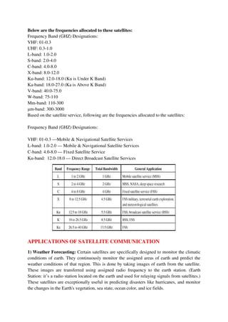
This document provides lecture notes on satellite communications. It begins with a brief history of satellite systems and the realization of the concept from an idea to launching the first artificial satellite Sputnik-1 by the Soviet Union in 1957. It describes the basic concepts of satellite communications including the space segment consisting of the satellite and ground control station. It also describes the ground segment consisting of fixed, transportable and mobile earth terminals. It discusses the evolution from early passive satellites that simply reflected signals to later active satellites that could amplify and transmit signals.
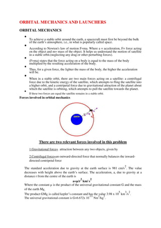
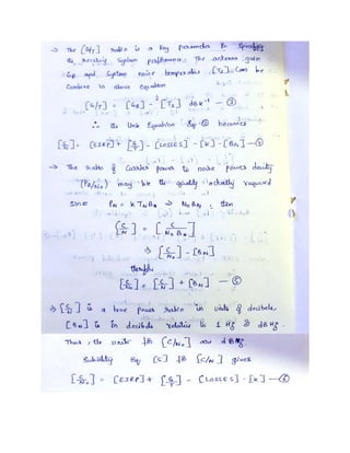
![The mass of the earth ME =5.97 x 10
24
kg.
Since fore= mass x acceleration, the centripetal force acting on the satellite, Fin is given by
Fin= m x (µ/r
2
)
=m x (G ME /r
2
)
In a similar fashion, the centrifugal acceleration is given by
a=v
2
/r
Which will give the centrifugal force, Fout as
Fout=m x(v
2
/r )
If the forces of the satellite are balanced Fin=Fout
m x (µ/r
2
)=m x(v
2
/r )
Hence the velocity v of the satellite in a circular orbit is given by
v=(µ/r)
1/2
If the orbit is circular, the distance traveled by a satellite in one orbit around a planet is 2∏r ,
where r is the radius of the orbit from the satellite to the center of the planet. Since distance
divided by velocity equals time to travel the distance, the period of satellite’s orbit, T, will be
T= (2∏r )/v = (2∏r )/[(µ/r)
1/2
]
T=(2∏r
3/2
)/(µ
1/2
)
Using standard mathematical procedures we can develop an equation for the radius of the
satellite’s orbit, r, namely
Kepler’s Laws
Kepler’s laws of planetary motion apply to any two bodies in space that interact through
gravitation. The laws of motion are described through three fundamental principles.
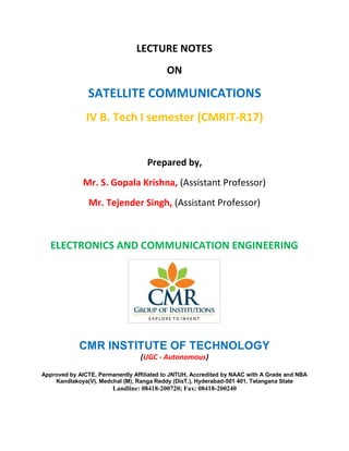
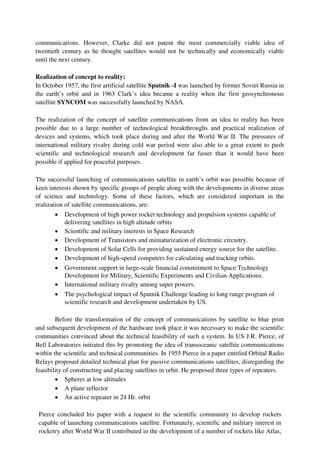
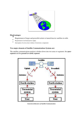
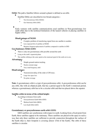
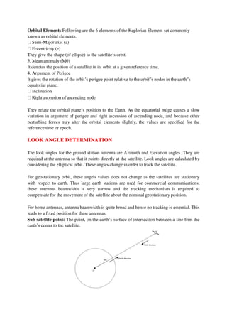
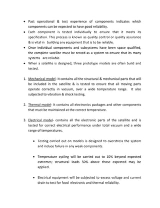
Kepler’s First Law, as it applies to artificial satellite orbits, can be simply stated as follows:
‘The path followed by a satellite around the earth will be an ellipse, with the center of mass
of earth as one of the two foci of the ellipse.’ This is shown in Figure:](https://image.slidesharecdn.com/satellitecommunicationnotesunit1to3-220509142530-f18d140e/85/Satellite-Communication-Notes-Unit-1-to-3-pdf-21-320.jpg)
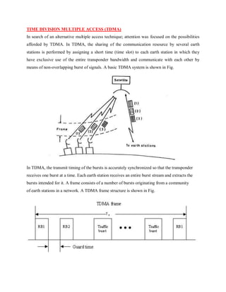
![If no other forces are acting on the satellite, either intentionally by orbit control or
unintentionally as in gravity forces from other bodies, the satellite will eventually settle in an
elliptical orbit, with the earth as one of the foci of the ellipse. The ‘size’ of the ellipse will
depend on satellite mass and its angular velocity.
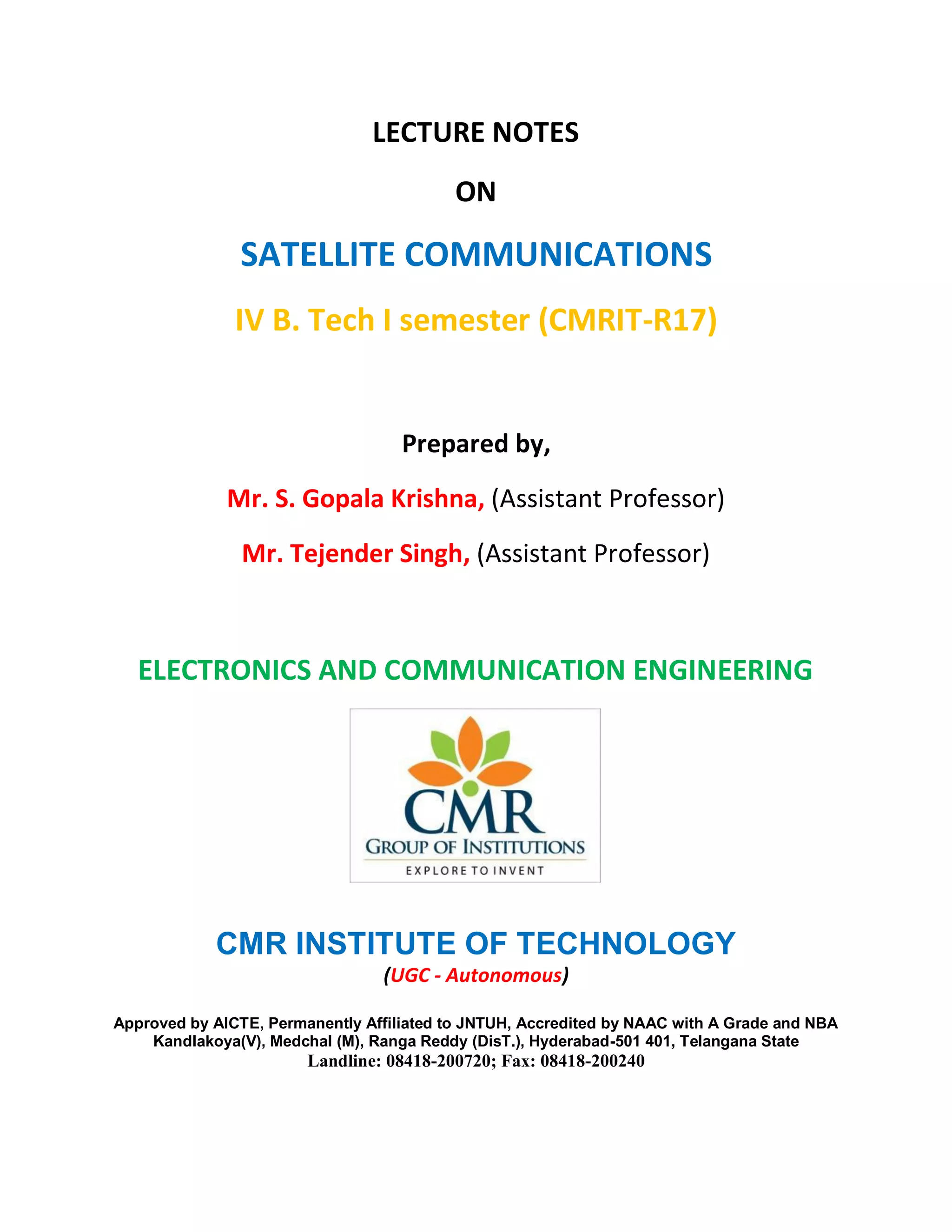
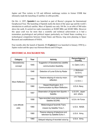
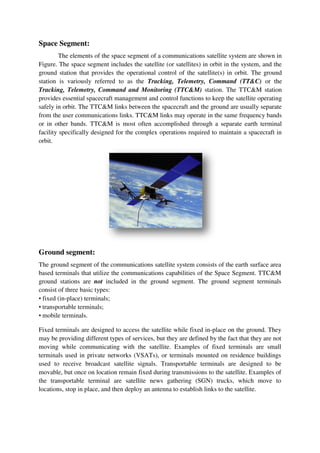
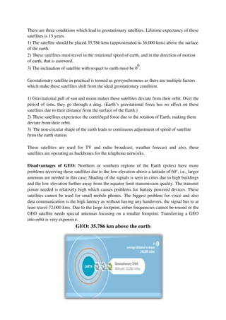
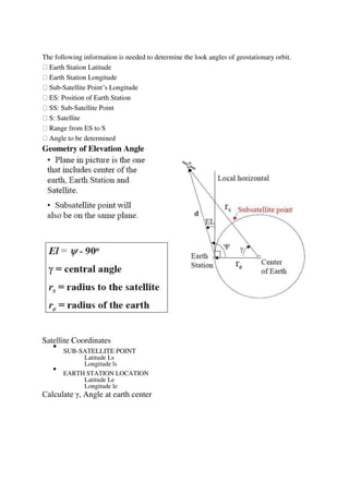
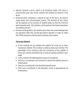
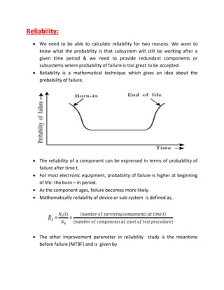
Kepler’s Second Law can likewise be simply stated as follows: ‘for equal time intervals, the
satellite sweeps out equal areas in the orbital plane.’ Figure 2.3 demonstrates this concept.
The shaded area A1 shows the area swept out in the orbital plane by the orbiting
satellite in a one hour time period at a location near the earth. Kepler’s second law states that
the area swept out by any other one hour time period in the orbit will also sweep out an area
equal to A1. For example, the area swept out by the satellite in a one hour period around the
point farthest from the earth (the orbit’s apogee), labeled A2 on the figure, will be equal to
A1, i.e.: A1 =A2.
This result also shows that the satellite orbital velocity is not constant; the satellite is moving
much faster at locations near the earth, and slows down as it approaches apogee. This factor
will be discussed in more detail later when specific satellite orbit types are introduced.
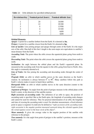
Kepler’s Third Law is as follows: ‘the square of the periodic time of orbit is proportional to
the cube of the mean distance between the two bodies.’ This is quantified as follows:
Where T=orbital period in s; a=distance between the two bodies, in km;
µ=Kepler’s Constant =3.986004×10⁵ km3/s2. If the orbit is circular,
then a=r, and
This demonstrates an important result: Orbit Radius = [Constant] × (Orbit Period)
2/3
Under this condition, a specific orbit period is determined only by proper selection of the
orbit radius. This allows the satellite designer to select orbit periods that best meet particular
application requirements by locating the satellite at the proper orbit altitude. The altitudes
required to obtain a specific number of repeatable ground traces with a circular orbit are
listed in Table 2.1.](https://image.slidesharecdn.com/satellitecommunicationnotesunit1to3-220509142530-f18d140e/85/Satellite-Communication-Notes-Unit-1-to-3-pdf-22-320.jpg)
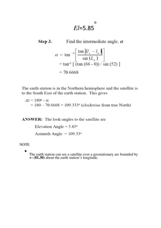


![Calculation of [C/N]:](https://image.slidesharecdn.com/satellitecommunicationnotesunit1to3-220509142530-f18d140e/85/Satellite-Communication-Notes-Unit-1-to-3-pdf-60-320.jpg)