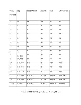
Downloaded 990 times


![CHAPTER-3
ARM7 MICROPROCESSOR
3.1 Introduction:
The ARM7TDMI core is a member of the ARM family of general-purpose 32-
bitMicroprocessors. The ARM [4] family offers high performance for very low power
Consumption and small size.
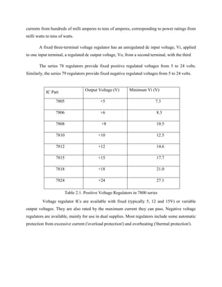
The ARM architecture as shown in fig 2.2 is based on Reduced Instruction Set Computer (RISC)
principles. The RISC instruction set and related decode mechanism are much simple than those
of Complex Instruction Set Computer (CISC) designs. This simplicity gives:
• A high instruction throughput
• An excellent real-time interrupt response
• A small, cost-effective, processor macro cell.
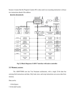
3.2The instruction pipeline:
The ARM7TDMI core uses a pipeline to increase the speed of the flow of instructions to
the processor. This enables several operations to take place simultaneously, and the processing
and memory systems to operate continuously.
A three-stage pipeline is used as shown in fig 2.1, so instructions are executed in three stages
Fig 3.1: The instruction pipeline
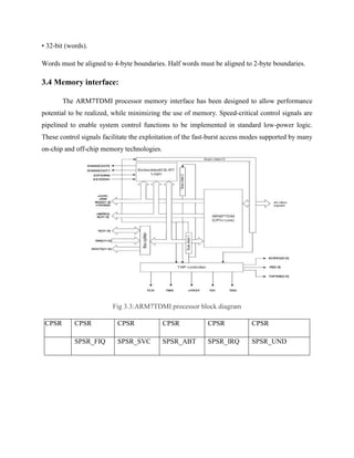
During normal operation, while one instruction is being executed, its successor is being
decoded, and a third instruction is being fetched from memory. The program counter points to
the instruction being fetched rather than to the instruction being executed. This is important](https://image.slidesharecdn.com/embeddedsystemfortrafficlightcontrol-140417215149-phpapp01/85/Embedded-system-for-traffic-light-control-31-320.jpg)
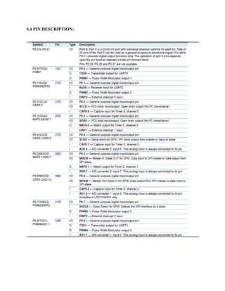

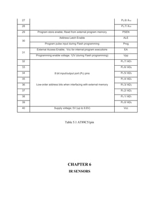
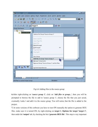


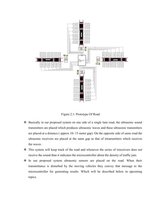
This document describes an embedded systems project for traffic light control. It presents the background and motivation for optimizing traffic light control using wireless sensors. The proposed system uses an ARM7 microcontroller programmed in embedded C to process real-time data from wireless sensors and control LED traffic lights accordingly. The goal is to study different traffic density situations and optimize traffic flow.