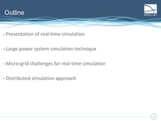
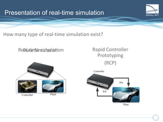
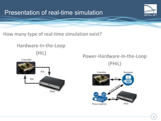
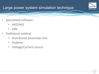
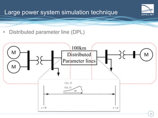
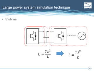
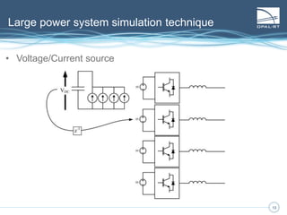
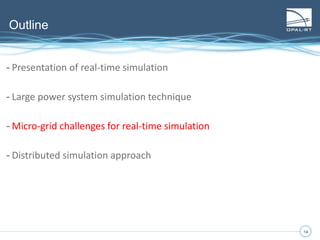
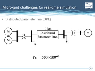
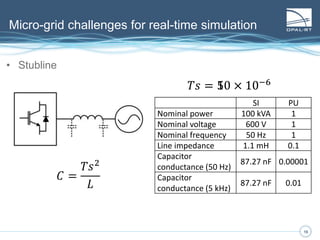
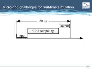
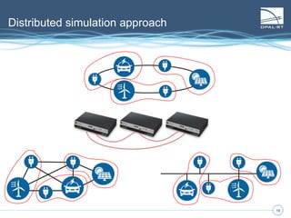
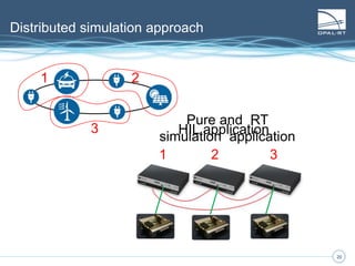
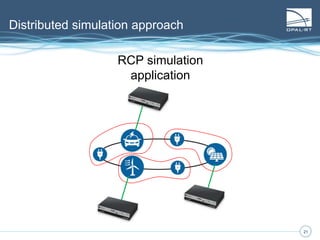
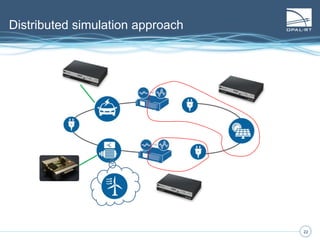
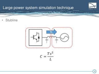
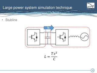
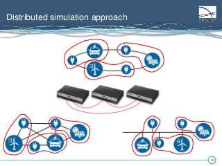
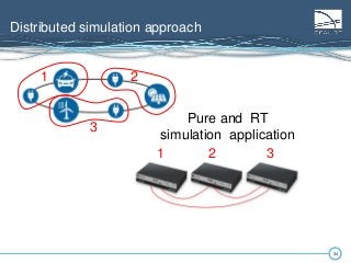
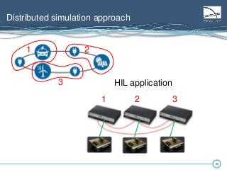
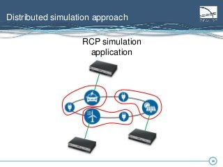
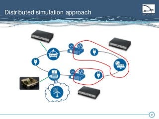
www.opal-rt.com
Real-time simulator requirement
for micro-grid simulation
vs large power system
Presented by
Luc-André Grégoire
International Conference on Industrial Technology
March 17th-19th, 2015
2
Outline
2
- Presentation of real-time simulation
- Large power system simulation technique
- Micro-grid challenges for real-time simulation
- Distributed simulation approach
3
Presentation of real-time simulation
How many type of real-time simulation exist?
Pure Simulation
Controller Plant
IOs
4
Presentation of real-time simulation
How many type of real-time simulation exist?
Controller Plant
IOs
Real-time simulation
5
Presentation of real-time simulation
How many type of real-time simulation exist?
Rapid Controller
Prototyping
(RCP)
IOs
Controller
Plant
IOs
Controller Plant
IOs
Real-time simulation
6
Presentation of real-time simulation
6
How many type of real-time simulation exist?
IOs
Controller
Plant
IOs
Hardware-In-the-Loop
(HIL)
7
Presentation of real-time simulation
7
How many type of real-time simulation exist?
IOs
Controller
Plant
IOs
Hardware-In-the-Loop
(HIL)
Controller
Plant
Real-plant
Power amplifier
Power signals
IOs
IOs
Power-Hardware-In-the-Loop
(PHIL)
8
Presentation of real-time simulation
8
How does real-time simulation work?
9
Presentation of real-time simulation
9
How does real-time simulation work?
𝑋 = 𝐴𝑋 + 𝐵𝑈
𝑌 = 𝐶𝑋 + 𝐷𝑈
𝑋 𝑛 = 𝐴𝑋 𝑛−1 + 𝐹𝑈 𝑛
𝑌𝑛 = 𝑃𝑋 𝑛−1 + 𝑄𝑈 𝑛
𝑒𝑞𝑢𝑎𝑡𝑖𝑜𝑛𝑠 𝑠𝑜𝑙𝑣𝑒𝑑 𝑏𝑦 𝑅𝑇𝑆
𝑧 = 𝑒 𝑠𝑇
10
Presentation of real-time simulation
10
How does real-time simulation work?
11
Presentation of real-time simulation
11
How does real-time simulation work?
12
Presentation of real-time simulation
12
How does real-time simulation work?
13
Presentation of real-time simulation
13
How does real-time simulation work?
14
Presentation of real-time simulation
14
How does real-time simulation work?
15
Presentation of real-time simulation
15
How does real-time simulation work?
16
Presentation of real-time simulation
16
How does real-time simulation work?
𝑋 𝑎
𝑛
𝑋 𝑏
𝑛 =
𝐴 𝑎 0
0 𝐴 𝑏
𝑋 𝑎
𝑛_1
𝑋 𝑏
𝑛_1 +
𝐵𝑎 0
0 𝐵 𝑏
𝑈 𝑎
𝑛
𝑈 𝑏
𝑛
𝑋 𝑎
𝑛
𝑋 𝑏
𝑛 =
𝐴 𝑎 𝐴 𝑎𝑏
𝐴 𝑏𝑎 𝐴 𝑏
𝑋 𝑎
𝑛_1
𝑋 𝑏
𝑛_1 +
𝐵𝑎 𝐵 𝑎𝑏
𝐵 𝑏𝑎 𝐵 𝑏
𝑈 𝑎
𝑛
𝑈 𝑏
𝑛
17
Outline
17
- Presentation of real-time simulation
- Large power system simulation technique
- Micro-grid challenges for real-time simulation
- Distributed simulation approach
18
Large power system simulation technique
18
• Specialized software
• ARTEMiS
• SSN
• Traditional method
• Distributed parameter line
• Stubline
• Voltage/Current source
19
Large power system simulation technique
19
• Distributed parameter line (DPL)
20
Large power system simulation technique
20
• Distributed parameter line (DPL)
21
Large power system simulation technique
21
• Distributed parameter line (DPL)
22
Large power system simulation technique
22
• Stubline
23
Large power system simulation technique
23
• Stubline
𝐶 =
𝑇𝑠2
𝐿
Ts
24
Large power system simulation technique
24
• Stubline
Ts
𝐿 =
𝑇𝑠2
𝐶
Ts
25
Large power system simulation technique
25
• Voltage/Current source
26
Large power system simulation technique
26
• Voltage/Current source
27
Outline
27
- Presentation of real-time simulation
- Large power system simulation technique
- Micro-grid challenges for real-time simulation
- Distributed simulation approach
28
Micro-grid challenges for real-time simulation
28
• Distributed parameter line (DPL)
1 km
𝑇𝑠 = 50 × 10−6 𝑇𝑠 = 500 × 10−9
2929
• Stubline
𝐶 =
𝑇𝑠2
𝐿
Micro-grid challenges for real-time simulation
SI PU
Nominal power 100 kVA 1
Nominal voltage 600 V 1
Nominal frequency 50 Hz 1
Line impedance 1.1 mH 0.1
Capacitor
conductance (50 Hz)
2.18 µF 0.0025
Capacitor
conductance (5 kHz)
2.18 µF 0.25
𝑇𝑠 = 50 × 10−6
3030
• Stubline
𝐶 =
𝑇𝑠2
𝐿
Micro-grid challenges for real-time simulation
SI PU
Nominal power 100 kVA 1
Nominal voltage 600 V 1
Nominal frequency 50 Hz 1
Line impedance 1.1 mH 0.1
Capacitor
conductance (50 Hz)
2.18 µF 0.0025
Capacitor
conductance (5 kHz)
2.18 µF 0.25
SI PU
Nominal power 100 kVA 1
Nominal voltage 600 V 1
Nominal frequency 50 Hz 1
Line impedance 1.1 mH 0.1
Capacitor
conductance (50 Hz)
87.27 nF 0.00001
Capacitor
conductance (5 kHz)
87.27 nF 0.01
𝑇𝑠 = 10 × 10−6
3131
Micro-grid challenges for real-time simulation
32
Outline
32
- Presentation of real-time simulation
- Large power system simulation technique
- Micro-grid challenges for real-time simulation
- Distributed simulation approach
3333
Distributed simulation approach
3434
Distributed simulation approach
1 2
3
1 2 3
Pure and RT
simulation application
3535
Distributed simulation approach
1 2
3
1 2 3
HIL application
3636
Distributed simulation approach
RCP simulation
application
3737
Distributed simulation approach

Real-time simulator requirement for micro-grid simulation vs large power system

Editor's Notes

  • #3 In this presentation I’ll identify difference between microgrid and large network. Also the different application of RTS in microgrid application.
  • #4 1- Using RTS alone with both controller and plant simulated is pure simulation and not RT simulation.
  • #5 2- If IO are used to communicate between controller and plant then it is RT simulation
  • #6 3- When real-plant is available, RTS can be used to iterate different command law (very expensive DSP)
  • #7 1- Once you’ve bought a small DSP and implemented your controller, plant can be simulated for various test (see what happen for a 40kVdc phase-phase fault not safe for lab test) 2- HIL can also be used to test some hardware using power amplifier.
  • #8 1- Once you’ve bought a small DSP and implemented your controller, plant can be simulated for various test (see what happen for a 40kVdc phase-phase fault not safe for lab test) 2- HIL can also be used to test some hardware using power amplifier.
  • #9 First you find equations to be solved and then you discretize them. Using fixed-step solver
  • #10 First you find equations to be solved and then you discretize them. Using fixed-step solver
  • #11 Fixed-step solvers are used since the model need to be synchronized with real world. 1- read input 2- solve model 3- output results
  • #12 If the model to solve is too big, it might not be possible to solve within 1 time-step One solution is to increase the time-step. Doing so a stable model can become unstable
  • #13 If the model to solve is too big, it might not be possible to solve within 1 time-step One solution is to increase the time-step. Doing so a stable model can become unstable
  • #14 If the model to solve is too big, it might not be possible to solve within 1 time-step One solution is to increase the time-step. Doing so a stable model can become unstable
  • #15 If the model to solve is too big, it might not be possible to solve within 1 time-step One solution is to increase the time-step. Doing so a stable model can become unstable
  • #16 Using decoupling method, equations can be decoupled and solved in parallel. Allowing to keep a smaller time-step. We need to go from 1st matrix to the 2nd
  • #17 Using decoupling method, equations can be decoupled and solved in parallel. Allowing to keep a smaller time-step. We need to go from 1st matrix to the 2nd
  • #19 Specialized software, with proprietary methods can be used Literature also refers to more open technique
  • #20 Taking into account propagation delay in a line, two system can be solved in parallel Rule of thumb 100km take at least 50µs Smaller time-step can still be used Dynamic of the system is rather slow, therefore 50µs is ok.
  • #21 Taking into account propagation delay in a line, two system can be solved in parallel Rule of thumb 100km take at least 50µs Smaller time-step can still be used Dynamic of the system is rather slow, therefore 50µs is ok.
  • #22 Taking into account propagation delay in a line, two system can be solved in parallel Rule of thumb 100km take at least 50µs Smaller time-step can still be used Dynamic of the system is rather slow, therefore 50µs is ok.
  • #23 Propagation delay again but parasitic capacitors are added to achieve same parameters as DPL with exactly 1 step delay
  • #24 Propagation delay again but parasitic capacitors are added to achieve same parameters as DPL with exactly 1 step delay
  • #25 Propagation delay again but parasitic capacitors are added to achieve same parameters as DPL with exactly 1 step delay
  • #26 When a large state is available, like a DC capacitor. If DC voltage is constant over 1 time-step, it can be decoupled. Each converter has a controlled voltage source, and the value is obtained by injecting each dc current in a capacitor
  • #27 When a large state is available, like a DC capacitor. If DC voltage is constant over 1 time-step, it can be decoupled. Each converter has a controlled voltage source, and the value is obtained by injecting each dc current in a capacitor
  • #29 Now instead of 50µs, Ts has to be around 500ns. Also generation is much small machine, therefore the inertia is much smaller too. Basically dynamics of smart-grid are much faster, requiring smaller time-step.
  • #30 In the case of STUBLINE, at 50µs, for a 0.1pu of impedance, gives a capacitor of 0.0025pu. Less than 1% losses so it is negligible at 50Hz. At 5kHz, it becomes 0.25pu which greatly impact results This can be all solved by reducing the time-step.
  • #31 In the case of STUBLINE, at 50µs, for a 0.1pu of impedance, gives a capacitor of 0.0025pu. Less than 1% losses so it is negligible at 50Hz. At 5kHz, it becomes 0.25pu which greatly impact results This can be all solved by reducing the time-step.
  • #32 1- Many RTS use different technology for IO and for computation 2- During input/ouput, conditionning can be done. Filtering, pulse generation 3- To some extend, the whole model could be done on FPGA reducing time step and therefore losses and latency 4- CPU can be used for slower computation, like a controller at 50µs while FPGA is running much faster
  • #34 Taking the different structure of microgrid: Ring Radial Mesh Regrouping some part of the model, it could then be distributed over different RTS. This can be achieved if High speed link are available Small time-step of simulation
  • #35 When flexible RTS are used, they can be used for different part of the project. 1- can be used for pure simulation and RT-simulation 2- Removing the CTRL from RTS, can be interfaced with external controller
  • #36 When flexible RTS are used, they can be used for different part of the project. 1- can be used for pure simulation and RT-simulation 2- Removing the CTRL from RTS, can be interfaced with external controller
  • #37 RCP simulation can be achieved if the microgrid is available in the lab. Even a mix between RPC, PHIL, etc…
  • #38 Some part of the circuit can be simulated, some can be real, interfaced with power amplifier