Downloaded 10 times
![IOSR Journal of Electrical and Electronics Engineering (IOSR-JEEE)
e-ISSN: 2278-1676 Volume 4, Issue 4 (Jan. - Feb. 2013), PP 24-29
www.iosrjournals.org
Maximum Power Point Tracking of DC To DC Boost Converter
Using Sliding Mode Control
1
R.Anusuyadevi, 2P.Suresh Pandiarajan,3 J.Muruga Bharathi
1,2,3
Assistant Professor
Department of Electronics and Communication Engineering
P.S.R.Rengasamy College of Engineering for Women, Sivakasi, Tamilnadu,India.
Abstract: A sliding mode controller is used to estimate the maximum power point as a reference for it to track
that point and force the PV system to operate in this point. In sliding mode control, the trajectories of the system
are forced to reach a sliding manifold of surface, where it exhibit desirable features, in finite time and to stay on
the manifold for all future time. The load is composed of a battery bank. It is obtained by controlling the duty
cycle of a DC-DC converter using sliding mode control. This method has the advantage that it will guarantee
the maximum output power possible by the array configuration while considering the dynamic parameters solar
irradiance and delivering more power to charge the battery.
The proposed system with sliding mode control is tested using MATLAB / SIMULINK platform in
which a maximum power is tracked under constant and varying solar irradiance and delivered to the battery
which increasing the current that is charging the battery and reduces the charging time.
Keywords— Sliding manifold, Solar irradiance, Photo voltaic system.
I. INTRODUCTION
Photo Voltaic (PV) systems are used as energy source in many cases. Most commonly applied PV
systems can be found in remote and rural areas where no public grid is available. Photovoltaic is the technology
that uses solar cells or an array of them to convert solar light directly into electricity. The power produced by the
array depends directly form factors that are not controlled by the human being as the cell‟s temperature and
solar irradiance. Usually the energy generated by these solar cells is used to provide electricity to a load and the
remaining energy is saved into batteries. Photovoltaic cells have a single operating point where the values of the
current and voltage of the cell result in a maximum power output.
By connecting the PV cell directly to a load or a battery, the output power can be severely reduced due
to load mismatching or, in case of a battery, load voltage mismatching. Since this operating point depends on
factors like temperature, solar irradiance and load impedance, a device capable of tracking the maximum power
point and force the PVM to operate at that point is required. A maximum power point tracker (MPPT) is a
device capable of search for the point of maximum power and, using DC-DC converters, extracts the maximum
power available by the cell [3-6]. By controlling the duty cycle of the switching frequency of the converter we
can change the equivalent voltage of the cell and by that, its equivalent resistance into the one in which the PVM
is in the maximum power operating point[1-2].
II. SYSTEM REQUIREMENTS AND TECHNICAL BACKGROUND
2.1. Photo Voltaic System
A typical small photovoltaic power system (off-grid) can contain the following components: solar PV
array, with a number of series/parallel interconnected solar modules and protection elements, a DC/DC
converter, a DC/AC inverter and a control system.[3-5]
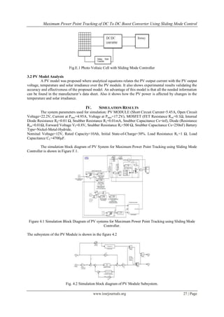
Figure.A.1 Basic Structure of Photo Voltaic System
The target of control system is that the PV array will maximize the electrical power with a given
irradiance. The control should guarantee that the dc power will be transformed with high efficiency to the load.
In order to archive the maximum power point (MPP) of the PV array, it is necessary maintain it at their optimum
www.iosrjournals.org 24 | Page](https://image.slidesharecdn.com/d0442429-130403050859-phpapp01/85/D0442429-1-320.jpg)
![IOSR Journal of Electrical and Electronics Engineering (IOSR-JEEE)
e-ISSN: 2278-1676 Volume 4, Issue 4 (Jan. - Feb. 2013), PP 24-29
www.iosrjournals.org
Maximum Power Point Tracking of DC To DC Boost Converter
Using Sliding Mode Control
1
R.Anusuyadevi, 2P.Suresh Pandiarajan,3 J.Muruga Bharathi
1,2,3
Assistant Professor
Department of Electronics and Communication Engineering
P.S.R.Rengasamy College of Engineering for Women, Sivakasi, Tamilnadu,India.
Abstract: A sliding mode controller is used to estimate the maximum power point as a reference for it to track
that point and force the PV system to operate in this point. In sliding mode control, the trajectories of the system
are forced to reach a sliding manifold of surface, where it exhibit desirable features, in finite time and to stay on
the manifold for all future time. The load is composed of a battery bank. It is obtained by controlling the duty
cycle of a DC-DC converter using sliding mode control. This method has the advantage that it will guarantee
the maximum output power possible by the array configuration while considering the dynamic parameters solar
irradiance and delivering more power to charge the battery.
The proposed system with sliding mode control is tested using MATLAB / SIMULINK platform in
which a maximum power is tracked under constant and varying solar irradiance and delivered to the battery
which increasing the current that is charging the battery and reduces the charging time.
Keywords— Sliding manifold, Solar irradiance, Photo voltaic system.
I. INTRODUCTION
Photo Voltaic (PV) systems are used as energy source in many cases. Most commonly applied PV
systems can be found in remote and rural areas where no public grid is available. Photovoltaic is the technology
that uses solar cells or an array of them to convert solar light directly into electricity. The power produced by the
array depends directly form factors that are not controlled by the human being as the cell‟s temperature and
solar irradiance. Usually the energy generated by these solar cells is used to provide electricity to a load and the
remaining energy is saved into batteries. Photovoltaic cells have a single operating point where the values of the
current and voltage of the cell result in a maximum power output.
By connecting the PV cell directly to a load or a battery, the output power can be severely reduced due
to load mismatching or, in case of a battery, load voltage mismatching. Since this operating point depends on
factors like temperature, solar irradiance and load impedance, a device capable of tracking the maximum power
point and force the PVM to operate at that point is required. A maximum power point tracker (MPPT) is a
device capable of search for the point of maximum power and, using DC-DC converters, extracts the maximum
power available by the cell [3-6]. By controlling the duty cycle of the switching frequency of the converter we
can change the equivalent voltage of the cell and by that, its equivalent resistance into the one in which the PVM
is in the maximum power operating point[1-2].
II. SYSTEM REQUIREMENTS AND TECHNICAL BACKGROUND
2.1. Photo Voltaic System
A typical small photovoltaic power system (off-grid) can contain the following components: solar PV
array, with a number of series/parallel interconnected solar modules and protection elements, a DC/DC
converter, a DC/AC inverter and a control system.[3-5]
Figure.A.1 Basic Structure of Photo Voltaic System
The target of control system is that the PV array will maximize the electrical power with a given
irradiance. The control should guarantee that the dc power will be transformed with high efficiency to the load.
In order to archive the maximum power point (MPP) of the PV array, it is necessary maintain it at their optimum
www.iosrjournals.org 24 | Page](https://image.slidesharecdn.com/d0442429-130403050859-phpapp01/75/D0442429-1-2048.jpg)
![Maximum Power Point Tracking of DC To DC Boost Converter Using Sliding Mode Control
point operating. The MPP varies with the solar radiation and the temperature. The characteristic curves specify a
unique operating point at which maximum possible power is delivered. At the MPP, the PV system operates at
its highest efficiency.
A control that regulates the voltage of the DC/DC converter and maximizes the power generated by the
photovoltaic array will be presented. The system consists of three closed loops, two inner loops and one outer
loop. The DC/DC converter has a control loop which regulates the output voltage irrespective of the input
voltage variations, and a sliding mode control that searches the maximum power point of the PV array. The
proposed system has an independent control loop for the PWM inverter.
In this control system, it is necessary to measure the PV array output power and to change the duty
cycle of the DC/DC converter control signal. So, the PV array output power is measured and compared to the
previous PV array output power. Depending on the result of the comparison, the optimal reference current of
sliding mode control is changed and the process is repeated until the maximum power is reached.[7-9]
2.2. DC to DC Boost Converter
The state-space model of the boost converter that will be used to evaluate the sliding mode control is
presented. A boost converter is simply is a particular type of power converter with an output DC. This type of
circuit is used to „step-up‟ a source voltage to a higher, regulated voltage, allowing one power supply to provide
different driving voltages. The basic boost converter circuit consists of only a switch (typically a transistor), an
inductor, and a capacitor
Figure.B.1 Boost Converter
Applying Kirchhoff‟s rules around the loops, it can obtain the ideal mathematical model of this circuit:
where iL is the current across the inductor, vo is the voltage in the capacitor. Parameters R , L and C are
supposed to be known constants. uϵ{0,1} defines the switch position and VPV is voltage supplied by
photovoltaic array. The gain from the boost converter is directly proportional to the duty cycle ( D ), or the time
the switch is „on‟ each cycle.
When boost converter is used in PV applications, the voltage input change continuously with
atmospheric conditions. Therefore, the duty cycle should change to track the maximum power point of
photovoltaic array. This converter should support input voltages in a wide range from 100 to 325 V. Under such
conditions, the duty ratio D is adjusted to regulate the output voltage at 400 V. For the given range, D is in a
range of [0.76-0.20] and the output current is maximum when D = 0.33. The 400 Volts obtained at boost
converter are applied to an IGBT two-level inverter to generate a sinusoidal output voltage of 50 Hz. The IGBT
inverter uses Pulse Width Modulation (PWM) at a 1050 Hz carrier frequency. The circuit is discretized at a
sample time of 1μs. The IGBT inverter is controlled with a PI regulator in order to maintain to 230 Vrms, 50 Hz
at the load terminals.
2.3. Maximum Power Point Tracking
A technique to utilize effectively the photovoltaic is known as a maximum-power- point tracking
(MPPT) method, which makes it possible to acquire as much power as possible from the photovoltaic. Since an
electric characteristic of the output power to the operating voltage or current has a convex property, there exists
only one optimum operating point on the power-voltage (or current) curve. The MPPT is a method to let the
controller operate at the above-mentioned optimum operating point. There have been various kinds of MPPT
methods reported and the most common technique of them is a hill-climbing method, which seeks the optimum
operating point by changing the operating voltage or current until the power becomes the maximum. Therefore,
this method essentially requires power calculation using both the voltage sensor and the current sensor.
www.iosrjournals.org 25 | Page](https://image.slidesharecdn.com/d0442429-130403050859-phpapp01/85/D0442429-2-320.jpg)
![Maximum Power Point Tracking of DC To DC Boost Converter Using Sliding Mode Control
2.3.1 Working of MPPT
MPPT is not a mechanical tracking system that “physically moves” the modules to make them point
more directly at the sun [3-6]. MPPT is a fully electronic system that varies the electrical operating point of the
modules so that the modules are able to deliver maximum available power. Additional power harvested from the
modules is then made available as increased battery charge current. MPPT can be used in conjunction with a
mechanical tracking system, but the two systems are completely different.
To understand how MPPT works, let‟s first consider the operation of a conventional (non-MPPT)
charge controller. When a conventional controller is charging a discharged battery, it simply connects the
modules directly to the battery. This forces the modules to operate at battery voltage, typically not the ideal
operating voltage at which the modules are able to produce their maximum available power.
Rather than simply connecting the module to the battery, the patented MPPT system in a Solar Boost
charge controller calculates the voltage at which the module is able to produce maximum power.[8-9].
2.4. Sliding Mode Control
Sliding mode control (SMC) is an important robust control approach. It is method which
transformed a higher-order system into first-order system. For the class of systems to which it applies, sliding
mode controller design provides a systematic approach to the problem of maintaining stability and consistent
performance in the face of modeling imprecision. On the other hand, by allowing the tradeoffs between
modeling and performance to be quantified in a simple fashion, it can illuminate the whole design process [11-
15].
Essentially, sliding mode control utilizes discontinuous feedback control laws to force the system state
to reach, and subsequently to remain on, a specified surface within the state space (the so called sliding or
switching surface). The system dynamic when confined to the sliding surface is described as an ideal sliding
motion and represents the controlled system behavior.
The design of the sliding mode control law can be divided in two phases:
1. Phase 1 consists in the construction of a suitable sliding surface so that the dynamic of the system confined to
the sliding manifold produces a desired behavior;
2. Phase 2 entails the design of a discontinuous control law which forces the system trajectory to the sliding
surface and maintains it there.
2.4.1 Sliding Mode Voltage Controlled (SMVC) Buck Converter
One of the most important features of sliding mode regime in variable structure systems (VSS) is the
ability to achieve responses that are independent of the system parameters, the only limit being the canonical
form description of the system. From this point of view, the Buck DC/DC converter is suitable for the
application of the SMC. The main advantage of this approach is that the switching frequency is constant under
all operating conditions, and it is easily controllable through varying the ramp signal. Basically, there are two
methods of implementing this constant frequency operation.
Sliding mode control implies that control actions are discontinuous state functions, which may easily
be implemented by conventional power converters with On-Off as the only admissible operation mode. Sliding
mode control has been proved to be applicable to a wide range of problems in robotics, electric drives and
generators, process control, vehicle and motion control. A sliding mode controller for buck converter is
proposed in this paper. A simple and easy to follow design procedure is described. Simulation results are
presented to explore the potentials of Sliding mode control for Buck converter.[10-12]
III. PROPOSED SYSTEM
3.1. Maximum Power Point Tracking Using Sliding Mode Controller
The proposed model will guarantee the extraction of the maximum power that can be produced by the
PVM while regulating the load voltage to the battery‟s voltage. That way we can have a workable load voltage
that can be connected to an inverter while matching the load resistance to the PV optimal resistance. The system
use a PV array (s x p) composed of s in series cells and p in parallel cells. It is then connected to a DC-DC
converter in order to increase or decrease the desired voltage. It is then connected directly to the load, which is
composed of a 12 V battery. The duty cycle of the converter is controlled by a sliding mode controller [1].
www.iosrjournals.org 26 | Page](https://image.slidesharecdn.com/d0442429-130403050859-phpapp01/85/D0442429-3-320.jpg)
![Maximum Power Point Tracking of DC To DC Boost Converter Using Sliding Mode Control
Table G.1 Comparison of results
TERMINAL
OPEN
VOLTAGE
CIRCUIT OPTIMAL MAXIMUM
WITH
INSOLATION VOLTAGE MPP POWER
LOAD
(SWITCH VOLTAGE OUTPUT
(SWITCH
OFF )
ON)
900 22.10V 17.12V 17.12V 76.87W
800 21.98V 17.03V 17.03V 68.31W
700 21.85V 16.93V 16.93V 59.54W
600 21.70V 16.81V 16.81V 50.61W
500 21.51V 16.67V 16.67V 41.58W
When the step response is given as the input, if insolation can be given in the range of 800 to 500, the
maximum power obtained first is 68.31W and slowly reduces to 41.58W finally at the settling value of
insolation 500.
V. CONCLUSION
The investigation demonstrates that the proposed sliding mode controller uses a non inverting Buck-
Boost converter in order to easily change the operation mode of the converter that can be necessary if the
optimal voltage of the PV module is lower than the battery voltage. The proposed algorithm is capable of
calculating the optimal voltage with little error.
The proposed controller only requires the array output voltage and the optimal voltage which is
continuously computed. From the simulation results is evident that a maximum power is tracked and achieved
by the proposed sliding mode controller under constant and varying solar irradiance delivered with the losses in
the converter, to the battery increasing the current that is charging the battery which, eventually, will reduce the
charging time.
References
[1] Emil A. Jimenez Brea, Eduardo I. Ortiz-Rivera, Andres Salazar-Llinas, Jesus Gonzalez-Llorente, May 2010, ”Simple Photovoltaic
Solar Cell Dynamic Sliding Mode Controlled Maximum Power Point Tracker for Battery Charging Applications”, IEEE
Transactions on power electronics, Vol. No.978-1-4244-4783-1, pp. 666-671.
[2] K. N. Hasan, M. E. Haque and M. Negnevitsky, 2008, ‟‟Control Of Energy Storage Interface With A Bidirectional Converter For
Photovoltaic Systems‟‟ Australasian Universities Power Engineering Conference.
[3] Wu Libo, Zhao Zhengming, Liu Jianzheng, Dec. 2007, “A Single-Stage Three Phase Grid-Connected Photovoltaic System With
Modified MPPT Method and Reactive Power Compensation”, Energy Conversion, IEEE Transaction on Vol. 22, Issue 4, pp. 881 –
886.
[4] l-Song Kim, 2007, “Robust Maximum power point tracker using sliding mode controller for the three-phase grid-connected
photovoltaic system”, .Solar Energy 81, pp. 415-414
[5] Il-Song Kim, Myung-Bok Kim, Myung-Joong Youn, August 2006, „„New Maximum Power Point Tracker Using Sliding-Mode
Observer For Estimation Of Solar Array Current In The Grid-Connected Photovoltaic System‟‟, IEEE Transactions On Industrial
Electronics, Vol. 53, No.4, pp. 1027-1036.
[6] Jae Ho Lee, Hyun Su Bae, Bo Hyung Cho, Aug 2006,“Advanced Incremental Conductance MPPT Algorithm with a Variable Step
Size”, Power Electronics and Motion Control Conference, EPE -PEMC 2006. 12th International, pp. 603 – 607.
[7] Femia, N.; Petrone, G.; Spagnuolo, G.; Vitelli, M., July 2005, “Optimization of perturb and observe maximum power point tracking
method”, IEEE Transactions on Power Electronics, Vol. 20, Issue 4, pp. 963– 973.
[8] A.M. Sharaf, Liang Yang, 2005, “An efficient Photovoltaic DC Village Electricity Scheme Using a Sliding Mode Controller”, IEE E
Conference on Control Applications, , pp 1325-1330.
[9] Femia, N. Petrone, G. Spagnuolo, G. Vitelli, May 2004, “Perturb and Observe MPPT technique robustness improved‟, IEEE
International Symposium on Industrial Electronics, Vol. 2, 4-7, pp. 845 -850 vol. 2
[10] Weidong Xiao; Dunford, W.G., June 2004, “A modified adaptive hill climbing MPPT method for photovoltaic power systems”,
Power Electronics Specialists Conference, PESC IEEE 35th Annual Vol.3, 20-25 pp. 1957 - 1963
[11] Yushaizad Yusof, Siti Hamizah Sayuti, Muhammad Latif, Zamri Che Wanik, 2004, “Modeling and Simulation of Maximum Power
Point Tracker for Photovoltaic System” , National Power & Energy Conference (PECon) Proceedings, Kuala Lumpur, Malaysia, pp.
88-93.
[12] Eduardo Ortiz, Fang Peng, 2000 „„A Novel Method To Estimate The Maximum Power For A Photovoltaic Inverter System‟‟, 35th
Annual IEEE Power Electronics Specialists Conference.
[13] Alexis de Medeiros Torres, Fernando Antunes, Fernando Soares, 1998, “An artificial Neural Network-Based Real Time Maximum
Power Tracking Controller for connecting a PV System to the grid”, IEEE, 0-7803-4503-7/98 pp. 554-559.
[14] Vietson M. Nguyen and C.Q. Lee, March 1996, ”Indirect implementations of sliding-mode control law in buck-type converters“,
Applied power electronics conference and Exposition (APSC) Vol 1 pp 111 – 115..
[15] Hanifi Guldemir, “Sliding Mode Control of DC/DC Boost Converter”, Journal of Applied Sciences 5(3), ISSN 1812-5654.
www.iosrjournals.org 29 | Page](https://image.slidesharecdn.com/d0442429-130403050859-phpapp01/85/D0442429-6-320.jpg)

This document summarizes a research paper about using sliding mode control to track the maximum power point of a DC-DC boost converter in a photovoltaic system. A sliding mode controller estimates the maximum power point as a reference to force the PV system to operate at this point. The proposed system with sliding mode control is tested using MATLAB/SIMULINK under constant and varying solar irradiance conditions. The maximum power is tracked and delivered to charge a battery, increasing the charging current and reducing charging time. Keywords include sliding manifold, solar irradiance, and photovoltaic system.