


![Advantages :
Less distortion and more clarity
Reproducibility of film and cone placement [ using the XCP ]](https://image.slidesharecdn.com/radiographsinendodontics-140121154159-phpapp02/75/Radiographs-in-endodontics-20-2048.jpg)


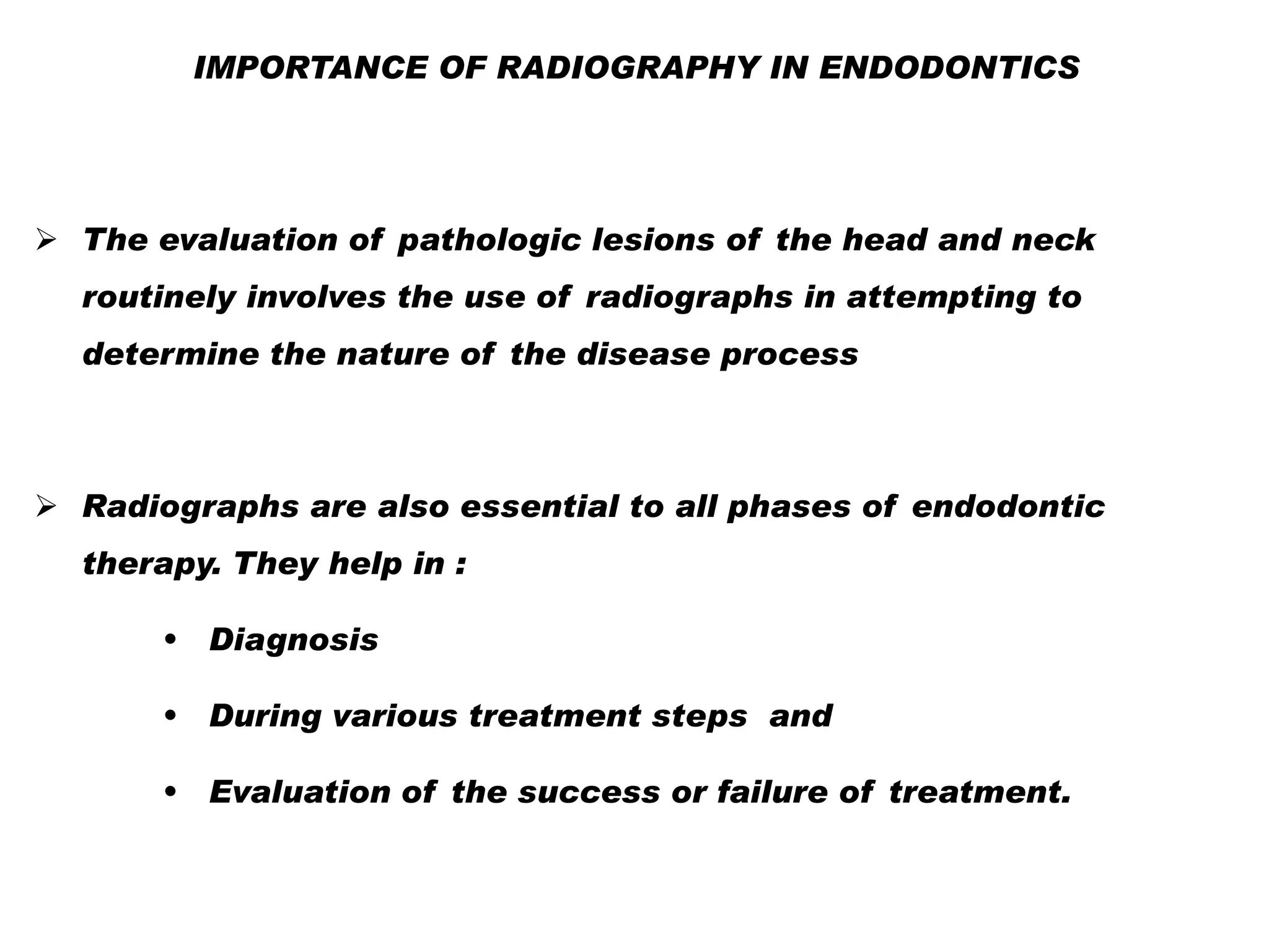
![II. WORKING FILMS
These are the films which are used during the treatment
procedure.
Not essentially given to the patient for a record
These include
Working length radiograph
Master cone
During obturation [ intermediate ]](https://image.slidesharecdn.com/radiographsinendodontics-140121154159-phpapp02/75/Radiographs-in-endodontics-23-2048.jpg)


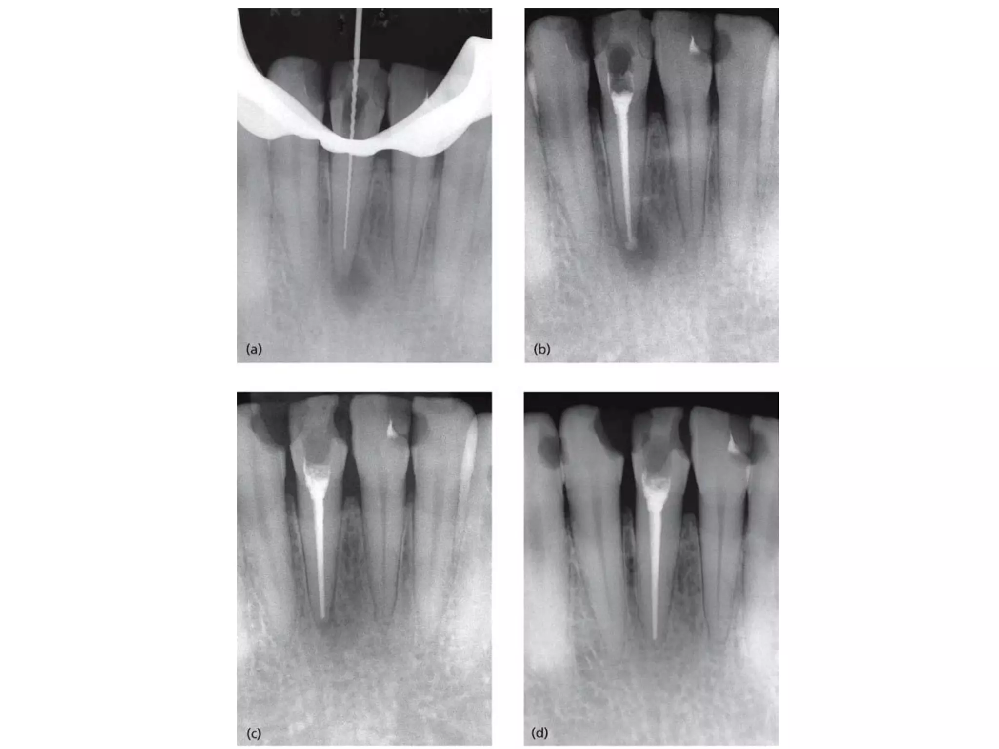
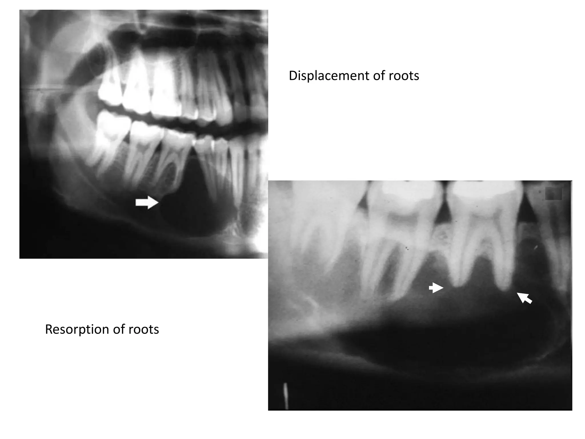
![Effect on adjacent structures
• Resorption
• Displacement
[Space occupying lesions displace other structures]
• Destruction
• Remodeling
•
Expansion](https://image.slidesharecdn.com/radiographsinendodontics-140121154159-phpapp02/75/Radiographs-in-endodontics-41-2048.jpg)


![Special Techniques :
Bitewing Projections : Useful in diagnosing dental caries
Especially the relation ship of the alveolar bone to the dental
caries [ proximal lesions]](https://image.slidesharecdn.com/radiographsinendodontics-140121154159-phpapp02/75/Radiographs-in-endodontics-54-2048.jpg)


![Micro Computed Tomography [Micro CT]
Cone beam CT](https://image.slidesharecdn.com/radiographsinendodontics-140121154159-phpapp02/75/Radiographs-in-endodontics-59-2048.jpg)


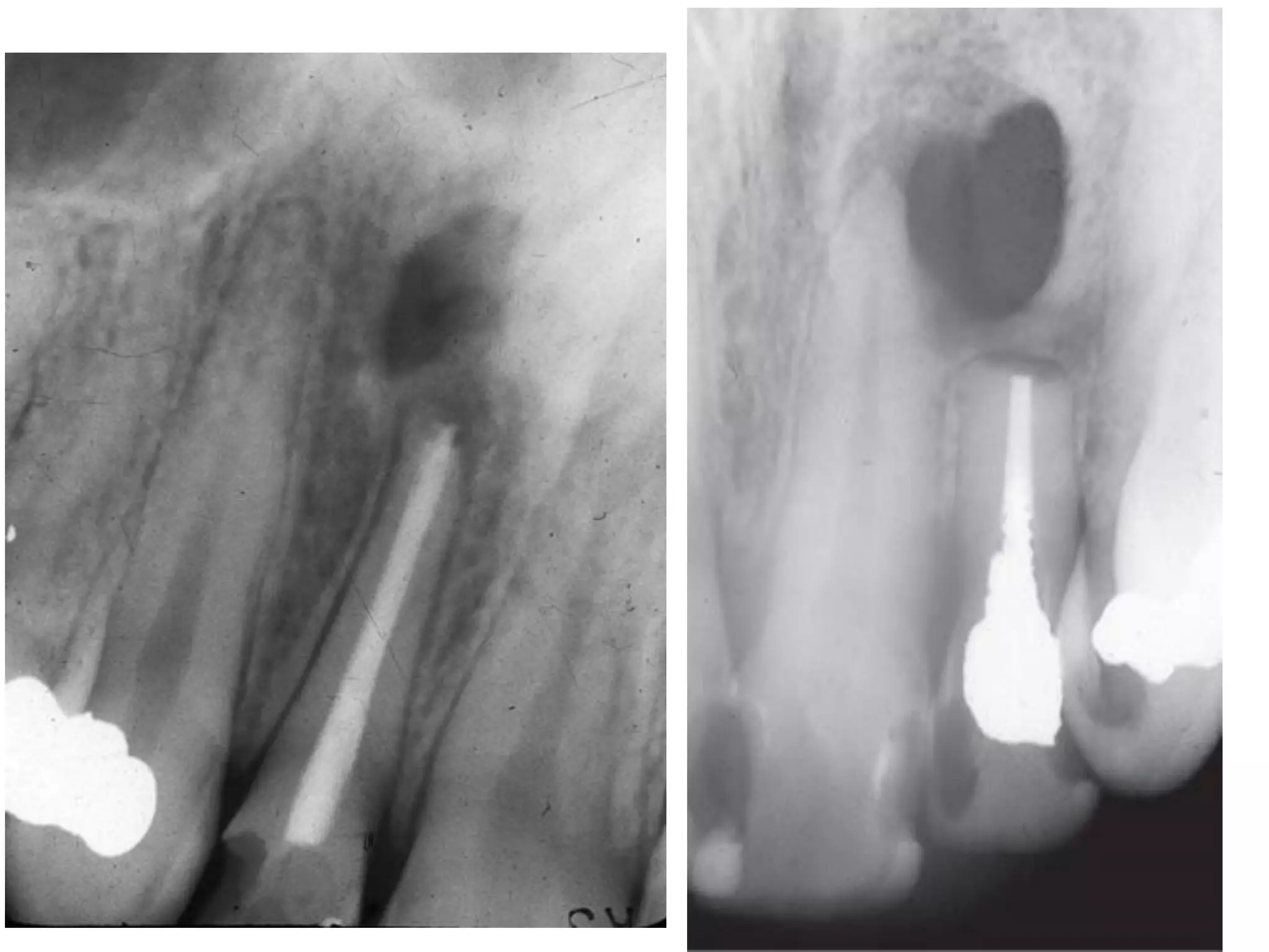
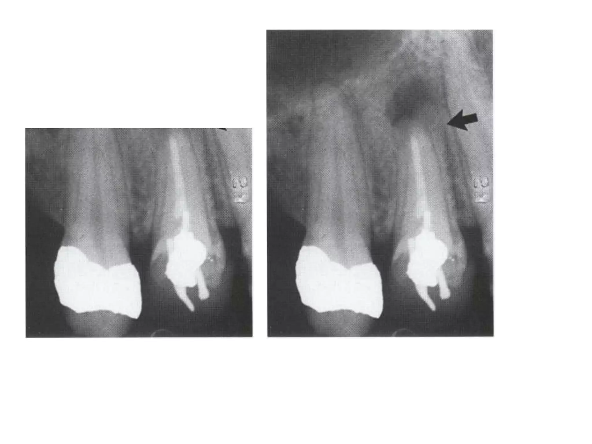
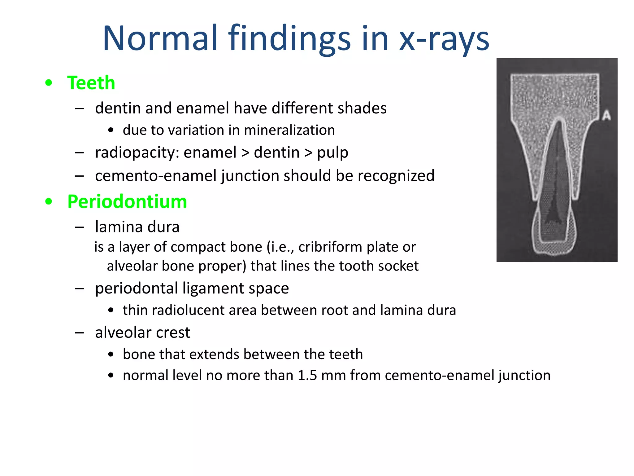
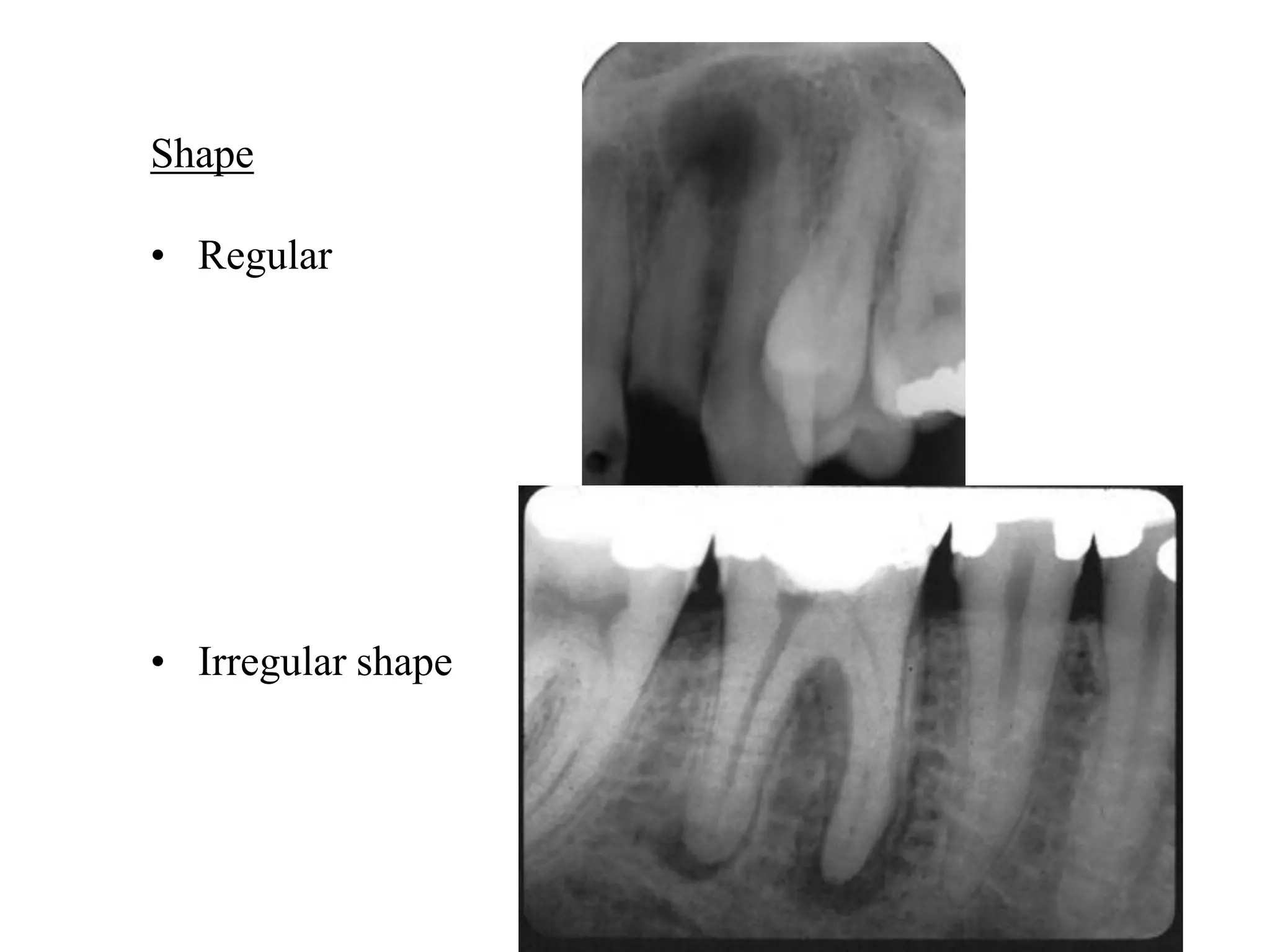
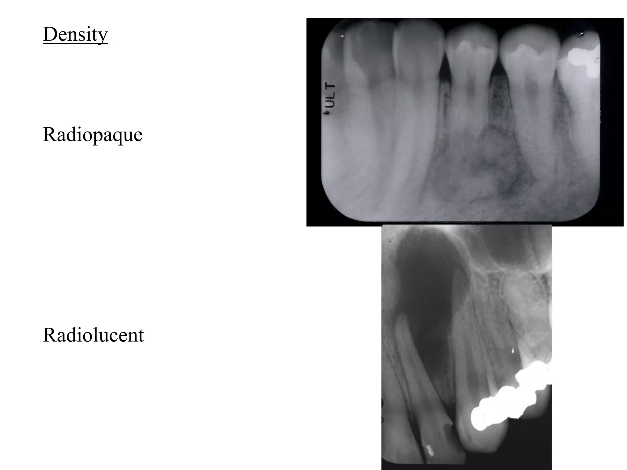
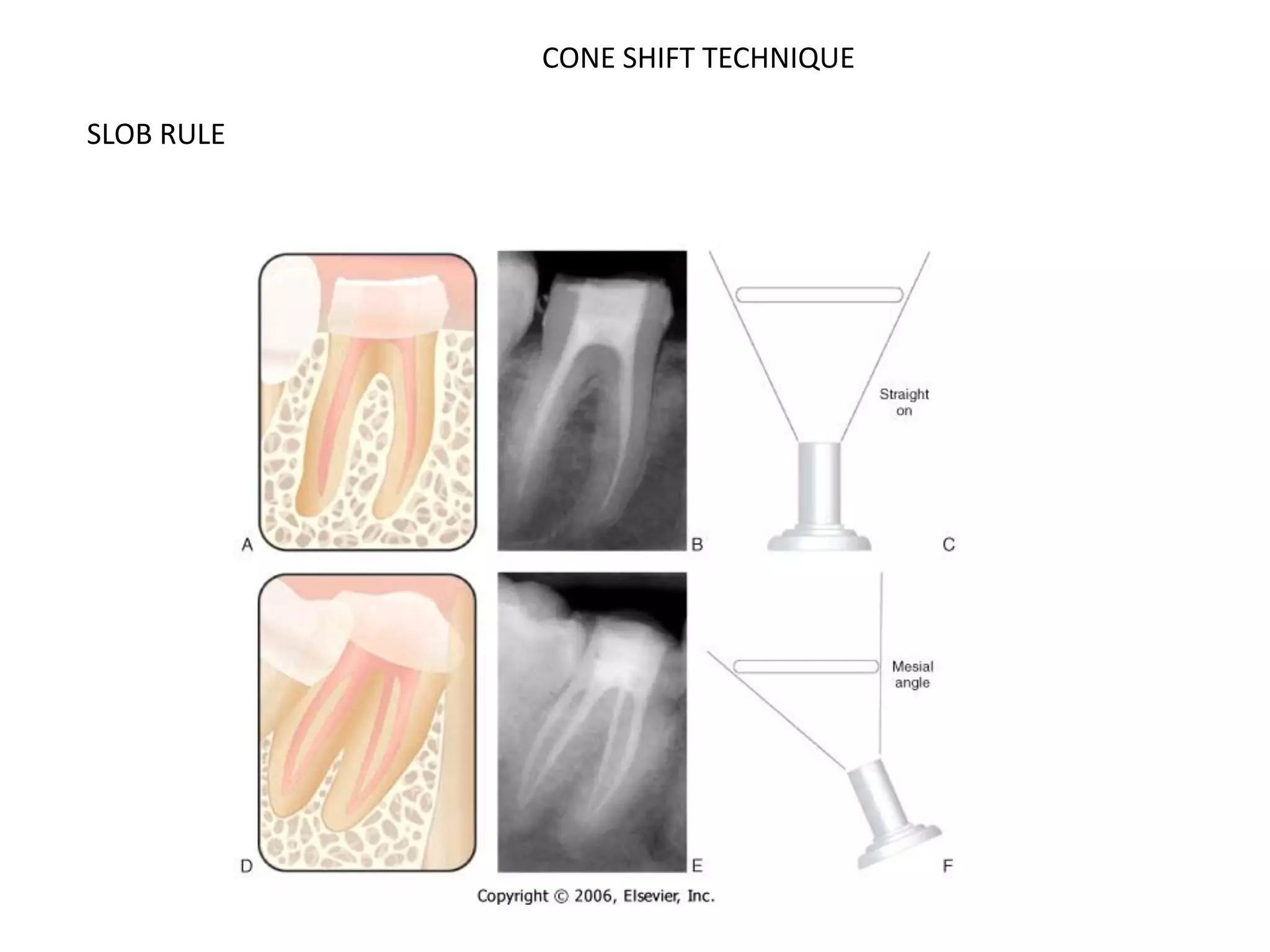
Radiography is essential for endodontic diagnosis, treatment, and evaluation of treatment outcomes. It helps determine pulpal and periapical pathology, root and canal morphology, working lengths, location of missed canals, and quality of obturation. Key radiographic views include diagnostic, working length, post-treatment, and recall films. Diagnostic films aim to visualize 3-4mm beyond the apex to identify lesions. Angulation and tube shift techniques help differentiate superimposed structures. Features like lamina dura continuity, lesion borders, density and effects on adjacent structures aid diagnosis. Newer technologies include digital radiography and cone beam CT for improved visualization of complex anatomy.


