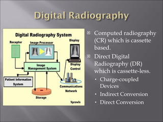
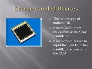
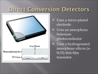
Computed radiography (CR) which is cassette based. Direct Digital Radiography (DR) which is cassette-less. Charge-coupled Devices Indirect Conversion Direct Conversion
Uses photostimulable storage phosphor imaging plates Uses existing tube equipment setup Needs special cassettes Uses a special cassette  reader Has a computer workstation, viewing station, and if hard copies are needed, a printer
Protective layer Insulates IP from handling trauma Phosphor layer Holds the photostimulable phosphor Support layer made of polyester The base on which the other layers are coated Conductor layer Grounds the IP eliminating electrostatic problems Light shield layer Prevents light from erasing data on the IP
 
 
Is a cassette-less system Uses a flat panel detector, or a charge-coupled device connected to a computer Needs new equipment installation.
This is one type of indirect DR It uses Gadolinium Oxysulfide as its X-ray scintillator It uses optical lenses to input the light from the scintillator screen onto the CCD
Uses Cesium Iodide or Gadolinium Oxysulfide as the X-ray scintillator Uses an amorphous Silicon photodiode to capture light and convert it into an electrical signal
This is a portion of an X-ray detector’s a-Si thin film transistor.
Uses a micro-plated electrode Uses an amorphous Selenium photoconductor Uses a hydrogenated amorphous silicon (a-Si:H) thin film transistor
Image Processing Toleration of Overexposure Sensitivity Data Clipping Spatial Frequency Processing Edge enhancement Image blurring Collimator Edge Identification
A histogram is generated by dividing a scanned area into pixels and determining the signal intensity for each pixel The histogram will be compared to the look-up table
CR and DR Imaging plates do not have the typical D log E curve, rather they have a straight line characteristic curve The processing computer compares the image receiver data to the look-up table, and is able to compensate for overexposure This opens the door for ALARA violations if a tech is purposely setting higher than necessary techniques
Manufacturers have designated a means to ensure adequate IP exposure levels The unit of measurement differs from manufacturer to manufacturer Fuji uses an S# and a S# of 200 equals 1mR of exposure Kodak’s system is the exposure index and 2000 equals 1mR of exposure Agfa uses a log median exposure (LgM) and a speed class
In most cases, the IP has more information stored on it than the display system allows Exposure data that falls above and below useful levels can be left out Also, data which the system deems as clinically irrelevant can be left out
EDGE ENHANCEMENT IMAGE BLURRING At times, a post-processing algorithm can be used on high noise images to blur the mottled noise into the background.
Artifacts unique to CR / DR can occur during Acquisition, Post-Acquisition, or Display This is an example of an image taken with an Agfa cassette backwards.
Phantom images can result from incomplete IP erasure Scratches from damaged plates Light spots caused by dust Fogging due to CR plates being more sensitive to scatter than film Quantum mottle Heat blur Dropout artifacts
Algorithm artifacts Dropout artifacts from laser imaging and other laser artifacts Histogram errors
Density / Brightness adjustments Contrast window width adjustments Electronic magnification adjustments Image enhancement artifacts
 

Digital Radiography

  • 1.
  • 2.
  • 3.
    Computed radiography (CR)which is cassette based. Direct Digital Radiography (DR) which is cassette-less. Charge-coupled Devices Indirect Conversion Direct Conversion
  • 4.
    Uses photostimulable storagephosphor imaging plates Uses existing tube equipment setup Needs special cassettes Uses a special cassette reader Has a computer workstation, viewing station, and if hard copies are needed, a printer
  • 5.
    Protective layer InsulatesIP from handling trauma Phosphor layer Holds the photostimulable phosphor Support layer made of polyester The base on which the other layers are coated Conductor layer Grounds the IP eliminating electrostatic problems Light shield layer Prevents light from erasing data on the IP
  • 6.
  • 7.
  • 8.
    Is a cassette-lesssystem Uses a flat panel detector, or a charge-coupled device connected to a computer Needs new equipment installation.
  • 9.
    This is onetype of indirect DR It uses Gadolinium Oxysulfide as its X-ray scintillator It uses optical lenses to input the light from the scintillator screen onto the CCD
  • 10.
    Uses Cesium Iodideor Gadolinium Oxysulfide as the X-ray scintillator Uses an amorphous Silicon photodiode to capture light and convert it into an electrical signal
  • 11.
    This is aportion of an X-ray detector’s a-Si thin film transistor.
  • 12.
    Uses a micro-platedelectrode Uses an amorphous Selenium photoconductor Uses a hydrogenated amorphous silicon (a-Si:H) thin film transistor
  • 13.
    Image Processing Tolerationof Overexposure Sensitivity Data Clipping Spatial Frequency Processing Edge enhancement Image blurring Collimator Edge Identification
  • 14.
    A histogram isgenerated by dividing a scanned area into pixels and determining the signal intensity for each pixel The histogram will be compared to the look-up table
  • 15.
    CR and DRImaging plates do not have the typical D log E curve, rather they have a straight line characteristic curve The processing computer compares the image receiver data to the look-up table, and is able to compensate for overexposure This opens the door for ALARA violations if a tech is purposely setting higher than necessary techniques
  • 16.
    Manufacturers have designateda means to ensure adequate IP exposure levels The unit of measurement differs from manufacturer to manufacturer Fuji uses an S# and a S# of 200 equals 1mR of exposure Kodak’s system is the exposure index and 2000 equals 1mR of exposure Agfa uses a log median exposure (LgM) and a speed class
  • 17.
    In most cases,the IP has more information stored on it than the display system allows Exposure data that falls above and below useful levels can be left out Also, data which the system deems as clinically irrelevant can be left out
  • 18.
    EDGE ENHANCEMENT IMAGEBLURRING At times, a post-processing algorithm can be used on high noise images to blur the mottled noise into the background.
  • 19.
    Artifacts unique toCR / DR can occur during Acquisition, Post-Acquisition, or Display This is an example of an image taken with an Agfa cassette backwards.
  • 20.
    Phantom images canresult from incomplete IP erasure Scratches from damaged plates Light spots caused by dust Fogging due to CR plates being more sensitive to scatter than film Quantum mottle Heat blur Dropout artifacts
  • 21.
    Algorithm artifacts Dropoutartifacts from laser imaging and other laser artifacts Histogram errors
  • 22.
    Density / Brightnessadjustments Contrast window width adjustments Electronic magnification adjustments Image enhancement artifacts
  • 23.