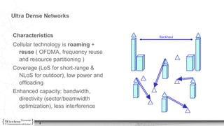
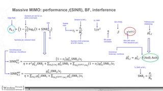
The document discusses various aspects of millimeter wave (mmWave) technologies and their applications in wireless communication networks, particularly in ultra-dense environments. It covers topics such as channel characteristics, beamforming techniques, interference management, and user association strategies in the context of mmWave communication. Additionally, it explores the challenges posed by blockages, mobility, and resource allocation in mmWave networks.

![11
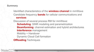
Mobility ManagementHandover
• Handovers in dense
deployments may be
frequent
• Limitations of RSS,
local load neglected
• Beam mismatch
triggers HO
• Dedicated backhaul
resources for the BSs
in soft or hard HO
Noise+Delay
• Increase of
overhead/delay due
to reassociation,
beam refiment and
CSI acquisition
• Cloud cell
(centralized arch.)
low latency
• Phase noise and
Doppler effect
increases with 𝑓𝑐
Robustness
• UE association with
multiple BS.
• Dual connectivity -
association but one
Tx per UE reduce
complexity
• Dynamic cell setting
+ user centric RRM
[ Athanasiou2015 ]](https://image.slidesharecdn.com/rrminmmwave-160826145653/85/Radio-Resource-Management-for-Millimeter-Wave-Massive-MIMO-11-320.jpg)


![MU- mimo [autosaved]](https://cdn.slidesharecdn.com/ss_thumbnails/massivemimoautosaved-190612174022-thumbnail.jpg?width=640&height=640&fit=bounds)


