The document presents an adaptive multi-state millimeter wave cell selection scheme (AMSMC-S) aimed at optimizing 5G communication performance through a flexible mechanism comprising three different classes of mmwave base stations. This scheme addresses the challenges associated with mmwave frequencies, such as high path loss and atmospheric absorption, by enabling user equipment to select the mmwave cell with the highest signal-to-interference plus noise ratio (SINR). Numerical results indicate that the proposed approach significantly reduces outage probability and enhances data rates for over 50% of users, achieving more than 1 Gbps.
![International Journal of Electrical and Computer Engineering (IJECE)
Vol. 8, No. 5, October 2018, pp. 2967~2978
ISSN: 2088-8708, DOI: 10.11591/ijece.v8i5.pp2967-2978 2967
Journal homepage: http://iaescore.com/journals/index.php/IJECE
Adaptive Multi-state Millimeter Wave Cell Selection Scheme
for 5G communications
Mothana L. Attiah1
, Azmi Awang Md Isa2
, Zahriladha Zakaria3
, Nor Fadzilah Abdullah4
,
Mahamod Ismail5
, Rosdiadee Nordin6
1,2,3
Centre for Telecommunication Research and Innovation (CeTRI), Faculty of Electronic and Computer Engineering
(FKEKK), Universiti Teknikal Malaysia Melaka (UTeM), Malaysia
1
Department of Computer Engineering, Electrical Engineering Technical College, Middle Technical University, Iraq
4,5,6
Faculty of Engineering and Built Environment, Universiti Kebangsaan Malaysia (UKM), Malaysia
Article Info ABSTRACT
Article history:
Received Dec 17, 2017
Revised Apr 13, 2018
Accepted Jul 25, 2018
Millimeter wave bands have been introduced as one of the most promising
solutions to alleviate the spectrum secrecy in the upcoming future cellular
technology (5G) due the enormous amount of raw bandwidth available in
these bands. However, the inherent propagation characteristics of mmWave
frequencies could impose new challenges i.e. higher path loss, atmospheric
absorption, and rain attenuation which in turn increase the outage probability
and hence, degrading the overall system performance. Therefore, in this
paper, a novel flexible scheme is proposed namely Adaptive Multi-State
MmWave Cell Selection (AMSMC-S) through adopting three classes of
mmWave base stations, able to operate at various mmWave carrier
frequencies (73, 38 and 28 GHz). Two mmWave cellular Grid-Based cell
deployment scenarios have been implemented with two inter-site-distances
200 m and 300 m, corresponding to target area of (2.1 km2) and (2.2 km2).
The maximum SINR value at the user equipment (UE) is taken in to
consideration to enrich the mobile user experience. Numerical results show
an improvement of overall system performance, where the outage probability
reduced significantly to zero while maintaining an acceptable performance of
the 5G systems with approximately more than 50% of the mobile stations
with more than 1Gbps data rate.
Keyword:
5G communications
Hybrid mmWave (BS) aproach
Mmwave frequency bands
Multiple mmwave connections
Outage probability
Copyright © 2018 Institute of Advanced Engineering and Science.
All rights reserved.
Corresponding Author:
Mothana L. Attiah,
Department of Telecommunication Engineering,
Faculty of Electronic and Computer Engineering,
Universiti Teknikal Malaysia Melaka,
Hang Tuah Jaya, 76100 Durian Tunggal, Melaka, Malaysia.
Email: mothana.utem@gmail.com
1. INTRODUCTION
Over the last decade, global telecom companies along with the forecasting groups were talking
about global data traffic growth around the world in the range of (Exabyte). Nowadays, the talk about
Zettabyte has become remarkably broad. Wherein, in [1], [2] the annual global IP traffic will reach 3.3 ZB by
2021, up from 1.2 ZB per year (one billion Gigabytes) per month. Further, this extraordinary growth can be
attributed to various advances in the technology with different factors form, more intelligence and multi-
objective capabilities [3], [4]. These considerations had become a burden on the network and cloud operators
pushing them to harness more efforts to satisfy the needs for extra bandwidth. Accordingly, millimeter wave
frequencies (28 GHz, 38 GHz, and 70-80 GHz) have been proposed as a promising candidates to satisfy the
future cellular communication (5G) requirements owning to the massive amount of spectrum bandwidth with
an extremely high frequency ringing from 30–300 GHz [5]. Despite of the attractive opportunity offered by](https://image.slidesharecdn.com/v3710410editndit-201118023823/85/Adaptive-Multi-state-Millimeter-Wave-Cell-Selection-Scheme-for-5G-communications-1-320.jpg)
![ ISSN: 2088-8708
Int J Elec & Comp Eng, Vol. 8, No. 5, October 2018 : 2967 - 2978
2968
mmWave frequency bands, there are unfavorable characteristics i.e. (i) the extra 20-40 dB path
loss [6], [7];(ii) the tiny wavelength signals of mmWave frequencies (1 to 100 mm) often has been thought
to contribute to higher attenuation through the air compared to the traditional below 6 GHz cellular band due
to oxygen absorption and precipitation[8]; (iii) the high susceptibility to be blocked completely by many
types of obstacle [9]-[12];(iv) the short coverage range of the mmWave with in (200 m) [13], [14].
On other hand, enhancing the spectral efficiency is another factor can effectively fuel the future
demands taking advantages from several approaches [15]. Consequently, many approaches have been
suggested in order to guarantee efficient and flexible resource utilization and hence, overcome the capacity of
radio networks limitations. For instance, an integration of macro and small cells called dual connectivity
(DC) was firstly introduced in Release (12) of LTE-A report [16], [17],built upon the functionality of the
concept which so-called carrier aggregation (CA)[18]. In light of the above approach, Multi-connectivity
(MC) architecture is presented in [19], [20] which is in one way or another inspired by the notion behind the
concept of dual connectivity. Furthermore, an optimal cell placement technique have been used with the
cooperation between microcells (MSs) and small cells (SCs) [21] to overcome the randomization of the
mmWave cell placement.
Particularly, mmWave base stations need to be densely distributed throughout a small area in order
to improve the coverage range and enhance the overall system performance [22]. However, the high-gain and
the highly directional antenna arrays at the transmitter (TX) and the receiver (RX) reinforces the suitability of
mmWave wireless communications [23]. As a result, in addition to the aforementioned studies there is a
specific research activities embarked on a study of the characteristics of the millimeter wave as well as its
enabling technologies, in which can be classified into two categories, mmWave measurement campaigns
activities and mmWave communication QoS assessment. In terms of the first category introducing mmWave
bands as promising candidates for 5G cellular system gives high priority for understanding of the special–
behavior of these bands. Based on this, extensive studies and set of measurements are conducted in [24]-[33].
Although, a few measurement campaigns conducted at high frequency (above 6GHz), there are some system
level assessments that obtained from those measurement campaigns, which opens up the road for building an
initial perception of 5G communication’s structure, MAC-Layer, system configurations, and its enabling
technologies. Accordingly, the first QoS evaluation with respect to SINR and average rate of mmWave
picocellular networks in a dense urban environment at 28GHz has been conducted in [34]. While, in [35] the
same inter-site- distance in previous work (200m) has been taken to evaluate two mmWave frequencies
(73 and 28 GHz). However, both of the aforementioned studies are performed and evaluated based on the
initial propagation measurements in most challenging environment in New York City (NYC).
Capturing and analyzing the key distinguishing marks of mmWave cellular networks have been
made using a tractable model developed in [36], and its extension in [37], which demonstrates that bandwidth
would have minimal effect on the rate of noise-limited cell edge users ( poor SINR user). In [38] the impact
of self-body blocking phenomena in millimeter wave communication has been evaluated in which proves
that even with self-body blocking mmWave outperforms the conventional cellular average rate. In [12], [39]
were proposed a stochastic geometry frameworks for analyzing the coverage and rate in mmWave cellular
networks to ensure the successful realization of utilizing high frequencies. In a more recent works, carrier
frequencies above 6-GHz have been targeted as in [11], [40] with a novel methods have been targeted to
characterize the benefits introduced by dynamic multi-connectivity techniques via exploiting coexistence
between 4G and mmWave base stations toward the realization of 5G networks. Moreover, mmWave/sub-6
GHz Multi-Connectivity with relaying is considered in [41] for enriching user-centric with high end-to-end
throughput in a cost-effective network deployment. Finally, in order to harvest the maximum benefit from
emerging mmWave technologies an efficient spectrum access scheme has been proposed in [7], wherein, two
hybrid spectrum accesses are utilized firstly, mmWave band with exclusive access and the second is pooled
between multiple operators.
In this article, we extend our work in [42], through an extensive investigation and we present a
useful assessment at extremely high carrier frequencies. However, different path loss model (the commonly
used close-in reference distance model) has been considered in order to investigate other parameters which
may affect the overall performance system as will be discussed in more detail later. New conceptual multiple
connection framework for the future 5G cellular communication has been provided. It is fully introduced and
analyzed consisting of a novel link-adaptive scheme (AMSMC-S), where UEs are capable of having parallel
links to three base stations. However, UE can only choose one of them based on the quality of these links.
According to the link-adaptive scheme, each user equipment attempts to rise up its own achievable data rate
and reduce the disconnection-mode via a suitably selecting its mmWave cell which is often carry the highest
signal-to-interference plus noise ratio (SINR). Three classes of mmWave cells/base stations (mBSs) are
considered based on grid-based network deployment adopting three-millimeter wave frequencies (73, 38 and
28 GHz) for outdoor users and outdoor infrastructure. Furthermore, with the use of this scheme it can be](https://image.slidesharecdn.com/v3710410editndit-201118023823/85/Adaptive-Multi-state-Millimeter-Wave-Cell-Selection-Scheme-for-5G-communications-2-320.jpg)
![Int J Elec & Comp Eng ISSN: 2088-8708
Adaptive Multi-state Millimeter Wave Cell Selection Scheme …. (Mothana L. Attiah)
2969
easily tested the impact of the adaptive/dynamic procedure under different parameters and different power
constraints targeting more challenging environments to harvest and realize the benefit of the hybrid mmWave
deployment.
The limitation of the dynamics of millimeter wave links and the large variations in signal level have
been overcome in this work through utilizing efficient millimeter wave cell and user tracking mechanism
inspired by the work in [40]. Our proposed scheme aims to guarantee both quality of service (QoS) and
quality of experience (QoE) as well exploiting the available resiliency of (AMSMC-S) to overcome the
quality of link degradation. Meanwhile, maintaining the co-channel interference in acceptable level and
guaranteeing sufficiently high availability.
2. AMSMC-S SCHEME
Our proposed scheme derives from the combination of several concepts that focus on the most
effected parameters such as average data rate and outage probability in addition to the densification of
millimeter wave base stations deployment. Based on this, utilizing of our proposed scheme relies on
providing a feasible optimal cell selection mechanism adopting different classes of millimeter wave cells.
Each class of mmWave cells adopts different level of mmWave frequency bands. More preciously, our
proposed scheme totally depends on maximum SINR value that delivered generally by either mmWave
Master-Cell (mMC) or mmWave Slave-Cell (mSC). Further, the theoretical concept of our proposed scheme
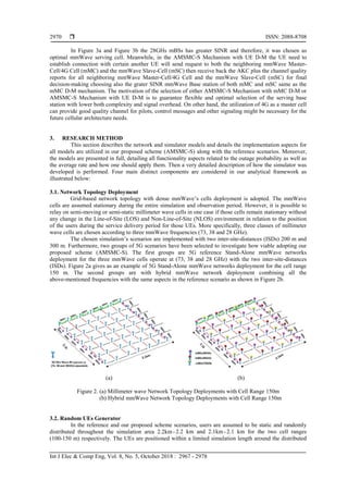
can be implemented through two main mechanisms as shown in Figure .3a and Figure .3b.
As depicted in Figure 3a and Figure 3b any mmWave cell offers grater SINR value to a certain
terminal i.e. (mobile station, IoE, etc.) than others will be the serving cell to that terminal. For instance, based
on AMSMC-S Mechanism with mMC D-M, the UE need to establish connection with another user or just
surfing the net it will send request to both the neighboring mmWave Master-Cell/4G Cell and the mmWave
Slave-Cell (mSC) then the mmWave Master-Cell/4G Cell will gather the channel quality of the three
mmWave Slave-Cells (28GHz mBSs, 38GHz mBSs and 73GHz mBSs) in addition to the channel quality of
itself. The higher mmWave cell channel quality the optimal selected serving cell for that terminal.
Figure 3. (a) AMSMC-S Mechanism with mMC D-M Figure 3. (b) AMSMC-S Mechanism with UE D-M](https://image.slidesharecdn.com/v3710410editndit-201118023823/85/Adaptive-Multi-state-Millimeter-Wave-Cell-Selection-Scheme-for-5G-communications-3-320.jpg)
![Int J Elec & Comp Eng ISSN: 2088-8708
Adaptive Multi-state Millimeter Wave Cell Selection Scheme …. (Mothana L. Attiah)
2971
millimeter wave cells. As the separation distance between the mmWave base station and the users play a
dominant role in determining the average receive signal, the UEs that are located closer to the millimeter
wave cells will certainly receive high average signal and thus, achieving in most of the time high quality of
service (QoS). Moreover, the power receiving value has directly impact on several parameters such as
Signal-to-Interference Plus Noise Ratio (SINR) means that any improvement in the quality of the receive
signal, in turn, improving the (SINR) value and hence, improving the overall system performance.
3.3. Mathematical models
In this paper, there are several key mathematical models are utilized. Some of them related to basic
mobile communications and the rest to mmWave communication system which are designated and developed
to be executed for producing one snapshot or more to get reasonable insights about the special behavior of
the millimeter wave system. In order to calculate the received signal at the receiving antenna we consider the
commonly used close-in reference distance path loss model represented in Equation (1) as in [14], [28],
[31],[32] based on the propagation measurement campaigns conducted by NYU WIRELESS researchers for
the three mmWave frequencies (73, 38 and 28 GHz).
UE
UE ,
,
( ) ( ) 10 log
10oi
o
i
d
PL d PL d n X
fs dϕ
ϕ
σ
= + × × +
, (1)
where ( )UE ,PL d
i ϕ stand for the average path loss in dB for a specific user or terminal UEi
and mmWave base
station ϕ separation distance of UE ,d
i ϕ in meters, do is the close-in free space reference distance (1m), ( )PL dfs o
stand for the close-in reference free space path loss in dB as identified in Equation (2), n stand for the average
path loss exponent, X σ stand for to zero mean Gaussian random variable with σ a standard deviation in (dB)
since 10dB shadowing margin used in our work.
4
( ) 20 log10
doPL dfs o
π
λ
× ×
= ×
, (2)
where λ denotes to the wavelength of the carrier frequency. The parameter of this model n and λ for the
mmWave frequencies (73, 38 and 28 GHz) are listed in Table 1.
Table 1. Statistical Path-loss Parameter [14] ,[32], [43].
Variable n [dB] λ [mm]
28GHz 3.4 10.71
38GHz 2.6 7.78
73GHz 3.3 4.106
Generically, the average received signal power at the UEs calculated using the path loss model that is
described earlier in [14], [28], [31], [32], combined with the link budget represented in the Equation (3) with
log-scale as [35], [44]:
[ ] [ ] [ ] [ ] [dB]
P P G G PL
r dBm t dBm t dBi r dBi
= + + − , (3)
where Pr
and Pt
are the received and transmitted power of mmWave mBS respectively. Gt and Gr are the
linear gains of the transmitter and the receiver antennas in dBi, respectively, PL stand for the average path
loss in dB. Based on our proposed scheme we can rewrite the Equation (3) to fit the assumptions of the
utilization of different classes of mmWave base station (mBSs) as shown below:
Pr [ ] [ ] [ ] [ ] [ ]
UE UEi i
dBm Pt dBm Gt dBi Gr dBi PL dBϕ ϕ ϕ ϕ ϕ
Ψ Ψ Ψ Ψ Ψ
= + + − , (4)
where Ptϕ
Ψ
and PrUEi ϕ
Ψ
are the received and transmitted power of mmWave mBS respectively, with specific
frequency band Ψ and with a certain number of ϕ ,since ϕ depends on the number of mBSs that deployed
throughout the simulation area, Gt and Gr are the linear gains of the transmitter and the receiver antennas in](https://image.slidesharecdn.com/v3710410editndit-201118023823/85/Adaptive-Multi-state-Millimeter-Wave-Cell-Selection-Scheme-for-5G-communications-5-320.jpg)
![ ISSN: 2088-8708
Int J Elec & Comp Eng, Vol. 8, No. 5, October 2018 : 2967 - 2978
2972
dBi, respectively, PL stand for the average path loss in dB. Ψ is considered as a set of sub-channel offered
by a three classes of mmWave base stations, sΨ ∈ since s =[1, 2, 3] and each value of s represent a certain
value of sub-channel of the three (73, 38 and 28 GHz) respectively.
if s =1 represents 73GHz mmWave Base Station 1,2,3....... nϕ ϕ=
=Ψ if s =2 represents 38GHz mmWave Base Station
if s =3 represents 28GHz mmWave Base Station
Basically, to measure system interference and examine its impact on network functionality, the SINR of a
specific user/terminal expressed byUEi connected to mBS Ψ under the determined number of ϕ is
calculated based on the Equation (5) [45]:
Pr
UEi
N
UEi
UEi I
ϕ
ϕ
ξ
ϕ
η
=1
Ψ
Ψ
Ψ
=
Ψ
+∑
, (5)
where UEi
ξ ϕ
Ψ is the Signal-to-interference plus noise ratio; IUEi ϕ
Ψ is the interference received by the receiver UEi
from the only same class of neighboring mBS Ψ except the serving mBS ϕ ; ηΨ is the additive white noise
power at the connected receiver UEi
connected to mBS with specific value of Ψ . The additive white noise
power UEi
η Ψ at the connected receiver UEi
with mmWave base station Ψ given by the Equation (6)[44]:
( ) ( )10 log10 10 log10 UE UEiUE ii
KT W NFsysη
Ψ ΨΨ
= × + × + , (6)
where ( )10 log 10 KTsys× is equal to -174 dBm/Hz for a system temperature of17C ; UEi
NF Ψ is the Noise Figure
of the receiver connected to Ψ in dB, set to 6dB. The calculated values of the Signal-to-interference plus
noise ratio ( UEi
ξ ϕ
Ψ ) are made to provide further user channel capacity calculation, thus the average rate of
overall mmWave system can be calculated using Shannon capacity theory is shown in Equation (7) [45]:
log 12
WUEiC MUE UEni i
ξϕ ϕ
Ψ
Ψ Ψ=× × + , (7)
where M denotes to the number of antenna arrays in the connected mmWave base station; UEi
W Ψ denotes to
the total amount of bandwidth of the specified Ψ . UEi
ξ ϕ
Ψ
denotes to the Signal-to-interference plus noise ratio
of the i
UE channel, n denotes to the number of users/terminals.
4. RESULTS AND DISCUSSION
Once the cornerstone of the 5G scenarios adopting millimeter wave technology with and without our
proposed scheme (AMSMC-S) have been presented with more details about its consideration and overview
structure, the next step is to evaluate the overall 5G mmWave system performance according to the
aforementioned scenarios. This section tries to answer a few research questions as stated:
a. How does a flexible wireless system provided by our proposed scheme can reduce the outage probability
and maximize the overall system average rate?
b. How viable our (AMSMC-S) scheme to reduce the complexity of the 5G system deployment?
The answers of two aforementioned questions with the evaluation of the two performance metrics
along with simulation parameter settings as in Table 2 will be the focus of attention in the following
subsections.
depends on the number of mBSs](https://image.slidesharecdn.com/v3710410editndit-201118023823/85/Adaptive-Multi-state-Millimeter-Wave-Cell-Selection-Scheme-for-5G-communications-6-320.jpg)
![ ISSN: 2088-8708
Int J Elec & Comp Eng, Vol. 8, No. 5, October 2018 : 2967 - 2978
2974
(AMSMC-S) and the state of the art regarding to the coverage probability (outage probability) which is
considered as the first performance metric.
The outage probability percentages that have been carried out adopting our proposed scheme
reduced significantly which enable the cell-edge users to have SINR more than (2dB) as compared to the
outage probability percentages that have been carried out in [7], [13], [34], [35], wherein, the cell-edge users
experience SINR lower than zero. additionally, the mmWave base station density in our work less than that
ones in the aforementioned benchmark studies. In order to sum-up the coverage probability evaluations
taking into account the simulation area (2.1 km2 and 2.2 km2) with the two allocated power transmission
constraints (30dBm-20dBm), the outage probability percentages of the aforementioned scenarios (5G) have
been gathered to build a clear vision of our proposed scheme as compared to the 5G mmWave stand-alone
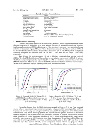
reference scenarios as shown in Figure 8 and Figure 9.
Figure 6. Downlink SINR CDF-Plot at (73, 38 and
28 GHz) for stand-alone deployment and our
proposed (AMSMC-S) Scheme with Pt= 30 dBm
(100 m cell range)
Figure 7. Downlink SINR CDF-Plot at (73, 38 and
28 GHz) for stand-alone deployment and our
proposed (AMSMC-S) Scheme with Pt= 20 dBm
(100 m cell range)
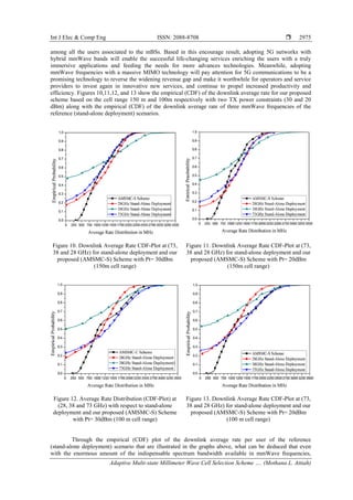
Figure 8. Overall Outage Probability Percentage of
(73, 38 and 28 GHz) for stand-alone deployment and
our proposed (AMSMC-S) Scheme with Pt=30dBm
and 20dBm and cell range (150m)
Figure 9. Overall Outage Probability Percentage of
(73, 38 and 28 GHz) for stand-alone deployment and
our proposed (AMSMC-S) Scheme with Pt=30dBm
and 20dBm and cell range (100m)
4.2. Average Rate Distribution
By using Shannon’s law illustrated in the Equation (6) the average rate of (490) users that are
randomly distributed adopting our scheme is more than (1Gbps) keeping in mind that the bandwidth splits](https://image.slidesharecdn.com/v3710410editndit-201118023823/85/Adaptive-Multi-state-Millimeter-Wave-Cell-Selection-Scheme-for-5G-communications-8-320.jpg)
![ ISSN: 2088-8708
Int J Elec & Comp Eng, Vol. 8, No. 5, October 2018 : 2967 - 2978
2976
severe limitation in the data rate is existed due the poor transmission signal which is resulted from the extra
attenuation of utilizing the high frequencies as well as their characteristics.
It merits saying, increasing the power transmission by +10 dBm slightly enhance the average rate by
approximately extra (5-7%) of the UEs experience data rate more than 1Gbps. Other key finding can be
deduced that the mobile location in terms of the mmWave base station plays an essential part of determining
the data rate. Particularly, when the mobile station (MS) served by the (73 GHz) mmWave base station
implies that the mobile (MS) will experience higher transmission rate than the mobile station (MS) which is
served by the 38GHz as well as 28 GHz mmWave base station due to higher availability of the spectrum
bandwidth taking into consideration how close the mobile station from the base station which operate at
(73 GHz). More specifically, another point can be drawn from the curves depicted in the graphs above that
adopting our proposed (AMSMC-S) scheme can significantly rise up the average rate of the overall mmWave
system. Furthermore, the average rate distribution per user for the two aforementioned cell ranges
(100m-150m) with different power constraints (30dBm-20dBm) utilizing of the proposed scheme can be
briefly clarified:
a. Approximately as an average 45–50% of the UEs experience better average rate (> 1Gbps).
b. (55–50%) of the UEs experience average rate within the range from (200 Mbps–1Gbps).
Based on this, our new conceptual mmWave (mBSs) deployment with the novel link-adaptive scheme
(AMSMC-S) outperforms the proposed approaches in the preliminary studies such as in [7], [13], [34], [35].
Thus, accelerating our pace to meet the required data rate for 5G cellular communication.
5. CONCLUSION
This paper proposes a novel Adaptive Multi-state mmWave Cell Selection (AMSMC-S) Scheme
providing a new conceptual of mmWave (mBSs) deployment for outdoor users and outdoor infrastructure
adopting flexible wireless communication with high transmission data rate. Particularly, when the (UEs) are
closer to the mmWave base stations. An optimal cell selection has been considered based on maximum SINR
value that are offered by three classes of mmWave base stations operating at three mmWave frequencies
(73, 38 and 28 GHz). Multiple performance metrics are taken into consideration to obtain a detailed
understanding of the potential issues and challenges, in addition to some encouraging results that pave the
road for the near future cellular communications (5G).
The simulation results have proven that there is a direct correlation between the mmWave base
stations density and the signal to interference plus noise ratio (SINR) value. On other hand, there is a tradeoff
between the average rate and the frequency, which has been utilized by the serving base station. Moreover,
approximately 45–55% of the UEs/Terminals experience better data rate (more than 1Gbps) with zero outage
probability which opens the way for conducting more studies utilizing a flexible mechanism maintaining
cross layer approach and guaranteeing efficient data delivering with user-centric quality along with different
initial access mechanisms based on hybrid slicing and sharing the resources among different operators
with/without taking the load balancing into consideration which remain as future work.
ACKNOWLEDGEMENTS
The authors gratefully acknowledge UTeM Zamalah Scheme, Universiti Teknikal Malaysia Melaka
(UTeM).
REFERENCES
[1] Cisco, '' Cisco Visual Networking Index: Forecast and Methodology, 2015-2020,'' Forecast Methodol., p. 22, 2015.
available [online] https://www.cisco.com/c/en/us/solutions/collateral/service-provider/visual-networking-index-
vni/complete-white-paper-c11-481360.pdf.
[2] Cisco,"The Zettabyte Era: Trends and Analysis,''. Cisco 2017, pp.1–29, 2017.
available[online]http://www.netmode.ntua.gr/courses/postgraduate/video_communications/2014/VNI_Hyperconnect
ivity_WP.pdf.
[3] Jofri MH, Fudzee MF, Ismail MN, Kasim S, Abawajy J.Quality of experience (QOE) aware video attributes
determination for mobile streaming using hybrid profiling. Indonesian Journal of Electrical Engineering and
Computer Science (IJEECS),2017; 8(3): 597–609.
[4] Lucrezia F, Marchetto G, Risso F, Santuari M, Gerola M. A Proposal for End-to-End QoS Provisioning in Software-
Defined Networks. International Journal of Electrical and Computer Engineering (IJECE), 2017;7(4): 2261–2277.
[5] Rappaport TS, Heath RW, Daniels RC, Murdock JN. Millimeter Wave Wireless Communications. United States:
Pearson Education, 2014:14–15.
[6] Ford R, Zhang M, Mezzavilla M, Dutta S, Rangan S, Zorzi M. Achieving Ultra-Low Latency in 5G Millimeter](https://image.slidesharecdn.com/v3710410editndit-201118023823/85/Adaptive-Multi-state-Millimeter-Wave-Cell-Selection-Scheme-for-5G-communications-10-320.jpg)
![Int J Elec & Comp Eng ISSN: 2088-8708
Adaptive Multi-state Millimeter Wave Cell Selection Scheme …. (Mothana L. Attiah)
2977
Wave Cellular Networks. IEEE Communications Magazine, 2017; 55(3):196–203.
[7] Rebato M, Boccardi F, Mezzavilla M, Rangan S, Zorzi M. Hybrid Spectrum Sharing in mmWave Cellular
Netwroks. IEEE Transactions On Cognitive Communications And Networking, 2017; 3(2):155–168.
[8] Pi Z, Khan F. An introduction to millimeter-wave mobile broadband systems. IEEE Communications
Magazine,2011; 49(6):101–107.
[9] Fund F, Shahsavar S, Panwar SS, Erkip E, Rangan S. Resource sharing among mmWave cellular service providers
in a vertically differentiated duopoly. IEEE ICC 2017 Next Generation Networking and Internet Symposi. Paris,
France. 2017:1–7.
[10] Rois JG, Lorenzo B, Gonźalez FJ, Burguillo JC. Hetrogeneous Millimeter-wave/Micro-wave Architecture for 5G
Wireless Access and Backhauling. 2016 IEEE European Conference on Networks and Communications (EuCNC).
Athens, Greece. 2016:179–184.
[11] Polese M, Giordani M, Mezzavilla M, Rangan S, Zorzi M. Improved Handover Through Dual Connectivity in 5G
mmWave Mobile Networks. IEEE Journal on Selected Areas in Communications, 2017;35(9):2069–2084.
[12] Turgut E,Gursoy MC. Coverage in heterogeneous downlink millimeter wave cellular networks. IEEE Transactions
On Communications,2017; 65(10): 4463–4477.
[13] Ford F,Cuba FG, Mezzavilla M, Rangan S. Dynamic time-domain duplexing for self-backhauled millimeter wave
cellular networks. IEEE ICC 2015-Workshop on Next Generation Backhaul/Fronthaul Networks (BackNets 2015).
London, United Kingdom.2015:13–18.
[14] Rappaport TS, MacCartney GR, Samimi MK, Sun S. Wideband Millimeter-Wave Propagation Measurements and
Channel Models for Future Wireless Communication System Design. IEEE Transactions on Communications, 2015;
63(9):3029–3056.
[15] Salh A, Audah L, Mohd Shah NS, Hamzah SA. Adaptive Antenna Selection and Power Allocation in Downlink
Massive MIMO Systems. International Journal of Electrical and Computer Engineering (IJECE),2017; 7(6): 3521–
3528.
[16] Ahmad SA, Datla D. Distributed Power Allocations in Heterogeneous Networks With Dual Connectivity Using
Backhaul State Information. IEEE Transactions on Wireless Communications, 2015; 14(8):4574–4581.
[17] Astely D, Dahlman E, Fodor G, Parkvall S, Sachs J. LTE Release 12 and Beyond. IEEE Communications Magazine,
2013; 51(7):104–111.
[18] Sesia S, Baker M, Toufik I. LTE-the UMTS long term evolution: from theory to practice. UK:John Wiley & Sons,
25 Jan 2011.
[19] Soret B, Wang H, Pedersen KI, Rosa C. Multicell cooperation for LTE-advanced heterogeneous network scenarios,"
IEEE Journals & Magazine,2013;20(1):27–34.
[20] Ghosh A, Thomas TA, Cudak MC, Ratasuk R, Moorut P, Vook FW, Rappaport TS, MacCartney GR, Sun S, Nie S.
Millimeter-wave enhanced local area systems: A high-data-rate approach for future wireless networks," IEEE
Journal on Selected Areas in Communications, 2014;32 (6);1152–1163.
[21] Banani SA, Eckford AW, Adve RS. Analyzing Dependent Placements of Small Cells in a Two-Layer
Heterogeneous Network with a Rate Coverage Constraint. IEEE Transactions on VehicularTechnology,
2016;65(12):9801–9816.
[22] Feng W, Wang Y, Lin D, Ge N, Lu J, Li S., When mmWave Communications Meet Network Densification: A
Scalable Interference Coordination Perspective. IEEE Journal on Selected Areas in Communications, 2017;
35(7):1459–1471.
[23] Li Y, Pateromichelakis E, Vucic N, Luo J, Xu W, Caire G. Radio Resource Management Considerations for 5G
Millimeter Wave Backhaul and Access Networks. IEEE Communications Magazine,2017; 55(6):86–92.
[24] Rappaport TS, Sun S, Mayzus R, Zhao H, Azar H, Wang K, Wong G, Schulz JK, Samimi M, Gutierrez F.
Millimeter wave Mobile Communications for 5G Cellular: It Will Work!. IEEE Access, 2013;1:335–349.
[25] Ben-Dor E, Rappaport TS, Qiao Y, Lauffenburger SJ. Millimeter-Wave 60 GHz Outdoor And Vehicle AOA
Propagation Measurements Using A Broadband Channel Sounder. 2011 IEEE Global Telecommunications
Conference-GLOBECOM 2011. Kathmandu, Nepal. 2011:8–13.
[26] Rappaport TS, Ben-Dor E, Murdock JN, Qiao Y. 38 GHz And 60 GHz Angle-Dependent Propagation for Cellular &
Peer-To-Peer Wireless Communications. 2012 IEEE International Conference on Communications (ICC). Ottawa,
ON, Canada. 2012: 4568–4573.
[27] Samimi M, Wang K, Azar Y, Wong JN, Mayzus R, Zhao H, Schulz JK, Sun S, Gutierrez F, Rappaport TS. 28 GHz
angle of arrival and angle of departure analysis for outdoor cellular communications using steerable-beam
antennas in New York City. 2013 IEEE 77th
Vehicular Technology Conference (VTC Spring). Dresden, Germany.
2013:1–6.
[28] Maccartney GR, Rappaport TS. 73 GHz Millimeter Wave Propagation Measurements for Outdoor Urban Mobile
And Backhaul Communications in New York City. 2014 IEEE International Conference on Communications (ICC).
Sydney, NSW, Australia. 2014: 4862–4867.
[29] Piersanti S, Annoni LA, Cassioli D. Millimeter Waves Channel Measurements And Path Loss Models. 2012 IEEE
International Conference on Communications (ICC). Ottawa,Canada. 2012: 4552–4556.
[30] Zhang H, Venkateswaran S, Madhow U. Channel Modeling And MIMO Capacity for Outdoor Millimeter Wave
Links. 2010 IEEE Wireless Communication and Networking Conference. Sydney, NSW, Australia. 2010:8–13.
[31] Rappaport TS, Gutierrez F, Ben-Dor E, Murdock JN, Qiao Y, Tamir JI. Broadband Millimeter-Wave Propagation
Measurements And Models Using Adaptive-Beam Antennas for Outdoor Urban Cellular Communications. IEEE
Transactions on Antennas and Propagation, 2013; 61(4):1850–1859.
[32] Azar Y, Azar Y, Wong GN, Wang K, Mayzus R, Schulz JK, Hang Zhao H, Gutierrez F, Hwang D, Rappaport TS.](https://image.slidesharecdn.com/v3710410editndit-201118023823/85/Adaptive-Multi-state-Millimeter-Wave-Cell-Selection-Scheme-for-5G-communications-11-320.jpg)
![ ISSN: 2088-8708
Int J Elec & Comp Eng, Vol. 8, No. 5, October 2018 : 2967 - 2978
2978
28 GHz propagation measurements for outdoor cellular communications using steerable beam antennas in New
York city. 2013 IEEE International Conference on Communications (ICC). Budapest, Hungary. 2013:5143–5147.
[33] Murdock JN, Ben-Dor E, Qiao Y, Tamir JI, Rappaport TS. A 38 GHz Cellular Outage Study For An Urban Outdoor
Campus Environment. 2012 IEEE Wireless Communications and Networking Conference (WCNC). Shanghai,
China. 2012: 3085–3090.
[34] Akdeniz MR, Liu Y, Rangan S, Erkip E. Millimeter wave picocellular system evaluation for urban deployments.
2013 IEEE Globecom Workshops (GC Wkshps). Atlanta, GA, USA. 2013:105–110.
[35] Akdeniz MR, Liu Y, Samimi MK, Sun S, Rangan S, Rappaport TS, Erkip E. Millimeter Wave Channel Modeling
and Cellular Capacity Evaluation. IEEE Journal on Selected Areas in Communications, 2014; 32(6):1164–1179.
[36] Singh S, Kulkarni MN, Andrews JG. A tractable model for rate in noise limited mmWave cellular networks. 2014
48th
Asilomar Conference on Signals, Systems and Computers. Pacific Grove, CA, USA. 2015:1911–1915.
[37] Singh S, Zhang X, Andrews JG. Joint Rate and SINR Coverage Analysis for Decoupled Uplink-Downlink Biased
Cell Associations in HetNets. IEEE Transactions on Wireless Communications, 2015;14(10):5360–5373.
[38] Bai T, Heath RW. Analysis of Self-Body Blocking Effects in Millimeter Wave Cellular Network. 2014 48th
Asilomar
Conference on Signals, Systems and Computers. Pacific Grove, CA, USA. 2014:1921–1925.
[39] Bai T, Heath RW. Coverage and Rate Analysis for Millimeter Wave Cellular Networks. IEEE Transactions on
Wireless Communications, 2015;14(2):1100–1114.
[40] Giordani M, Mezzavilla M, Rangan S, Zorzi M. Multi-connectivity in 5G mmWave cellular networks. 2016
Mediterranean Ad Hoc Networking Workshop (Med-Hoc-Net). Vilanova i la Geltru, Spain. 2016:1–7.
[41] Deng J, Tirkkonen O, Hollanti RF, Chen T, Nikaein N. Resource Allocation and Interference Management for
Opportunistic Relaying in Integrated mmWave/sub-6 GHz 5G Networks," IEEE Communications
Magazine,2017;55(6):94–101.
[42] Attiah ML, Ismail M, Nordin R, Abdullah NF. Dynamic multi-state ultra-wideband mm-wave frequency selection
for 5G communication. 2015 IEEE 12th
Malaysia International Conference on Communications (MICC). Kuching,
Malaysia. 2015:219–224.
[43] Hu F. Opportunities in 5G networks: A research and development perspective. United State : CRC press,30 Mar
2016.
[44] Rappaport TS, Murdock JN, Gutierrez F. State of the art in 60-GHz integrated circuits and systems for wireless
communications. Proceedings of the IEEE, 2011; 99(8):1390–1436.
[45] Naga Bhushan, Li J, Malladi D, Gilmore R, Brenner D, Damnjanovic A, Sukhavasi RT, Patel C, Geirhofer S.
Network Densification: The Dominant Theme for Wireless Evolution into 5G. IEEE Communications
Magazine,2014; 52(2): 82–89.](https://image.slidesharecdn.com/v3710410editndit-201118023823/85/Adaptive-Multi-state-Millimeter-Wave-Cell-Selection-Scheme-for-5G-communications-12-320.jpg)