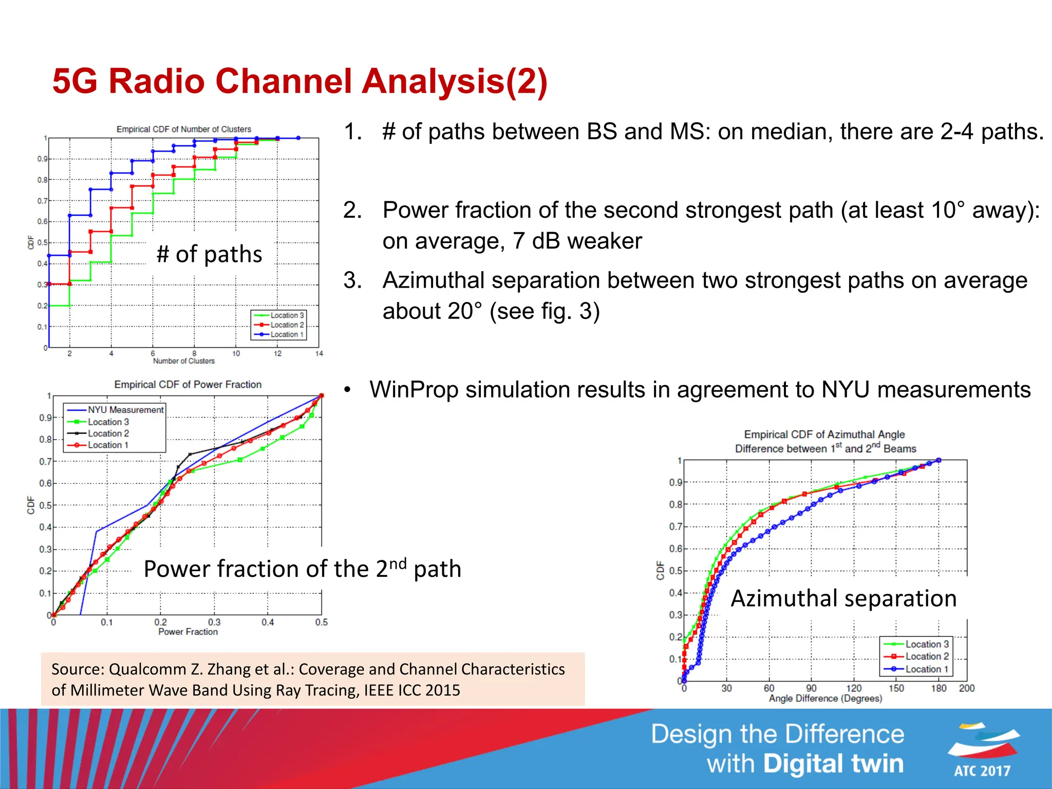
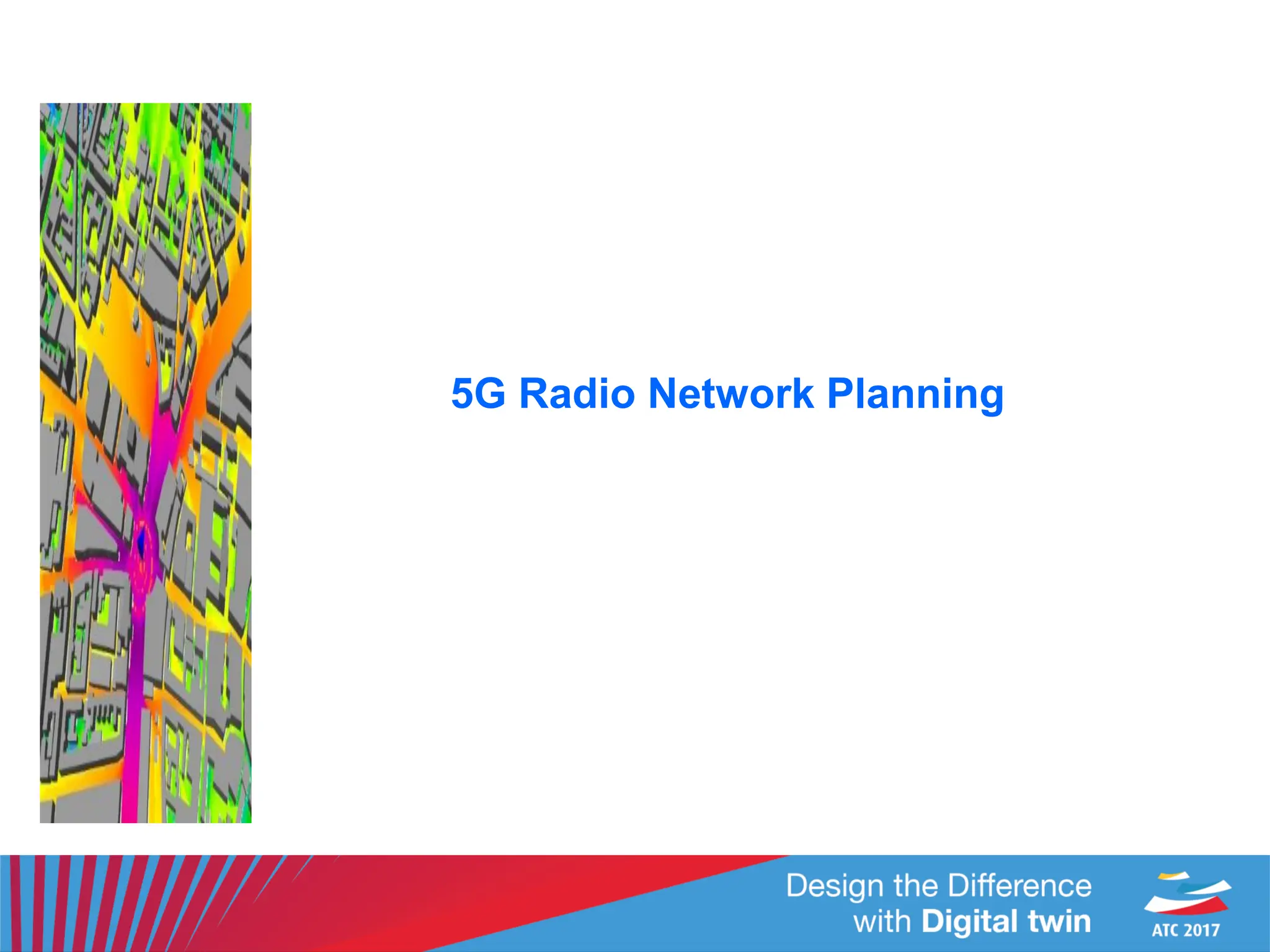
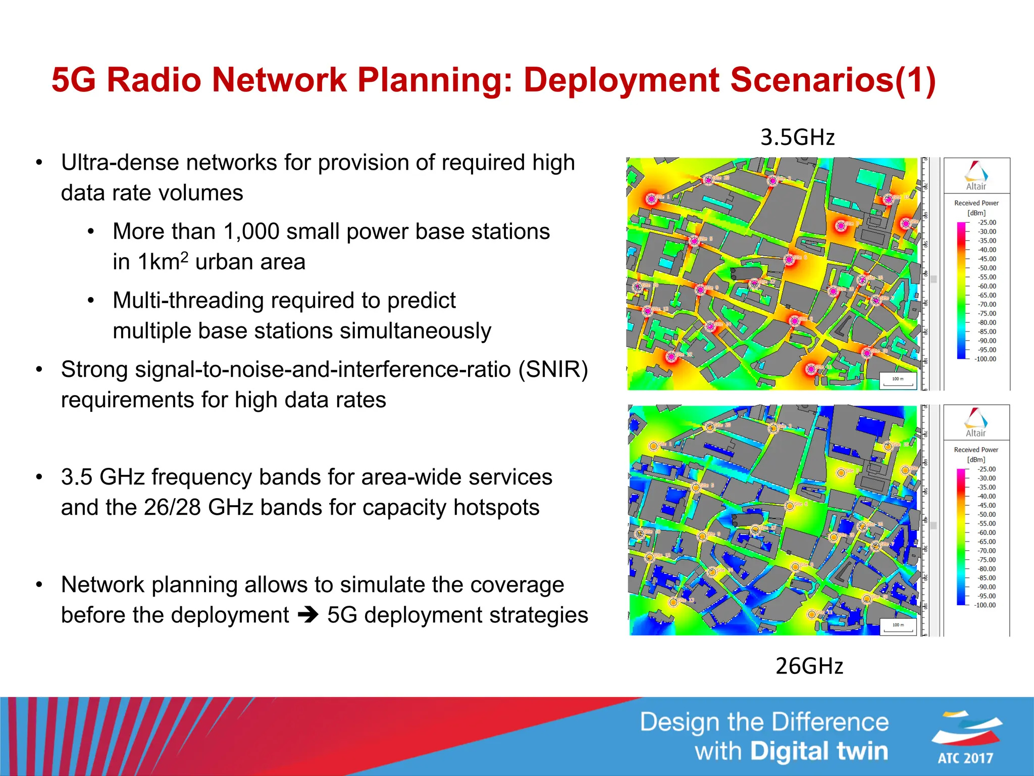
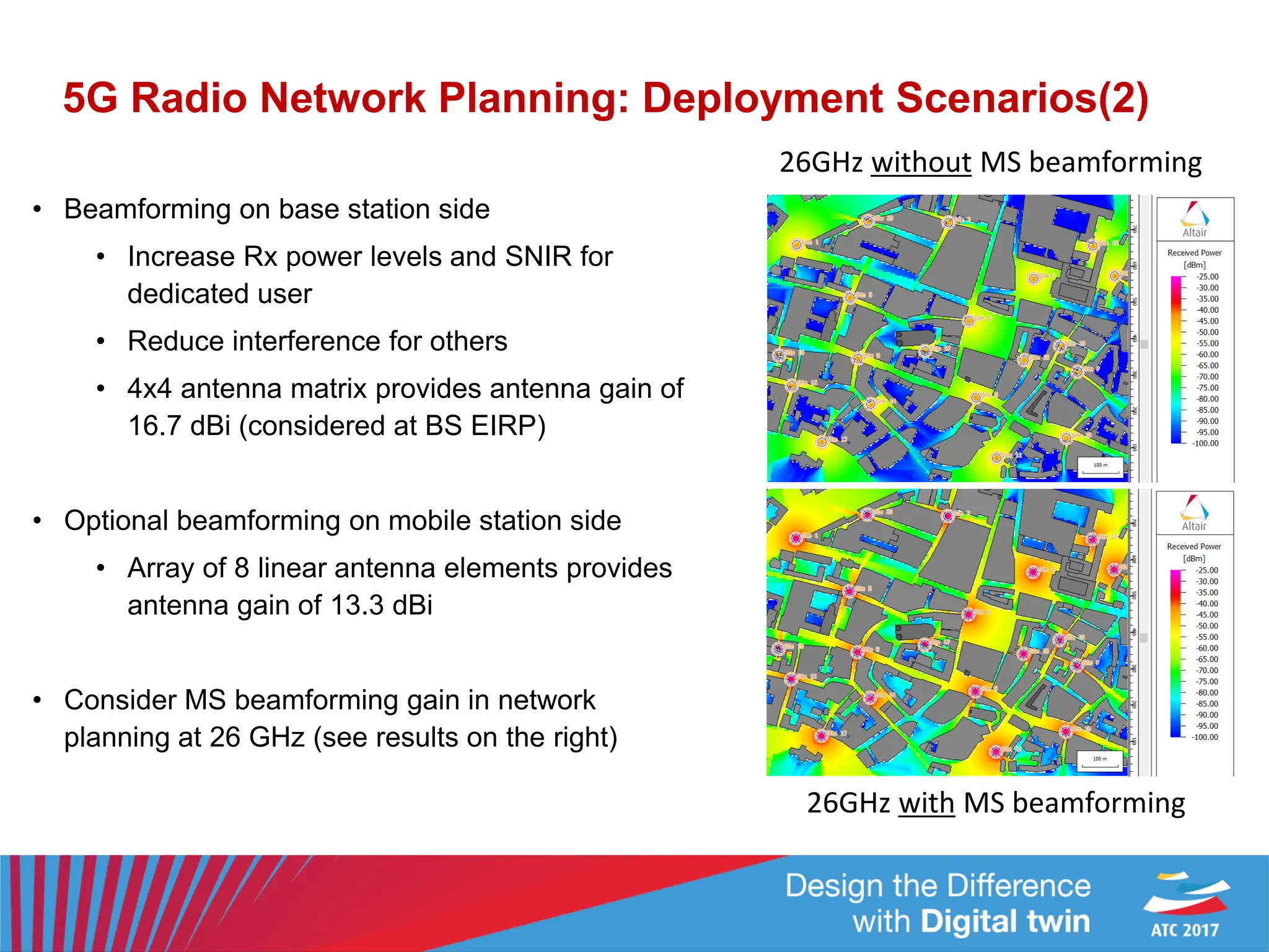
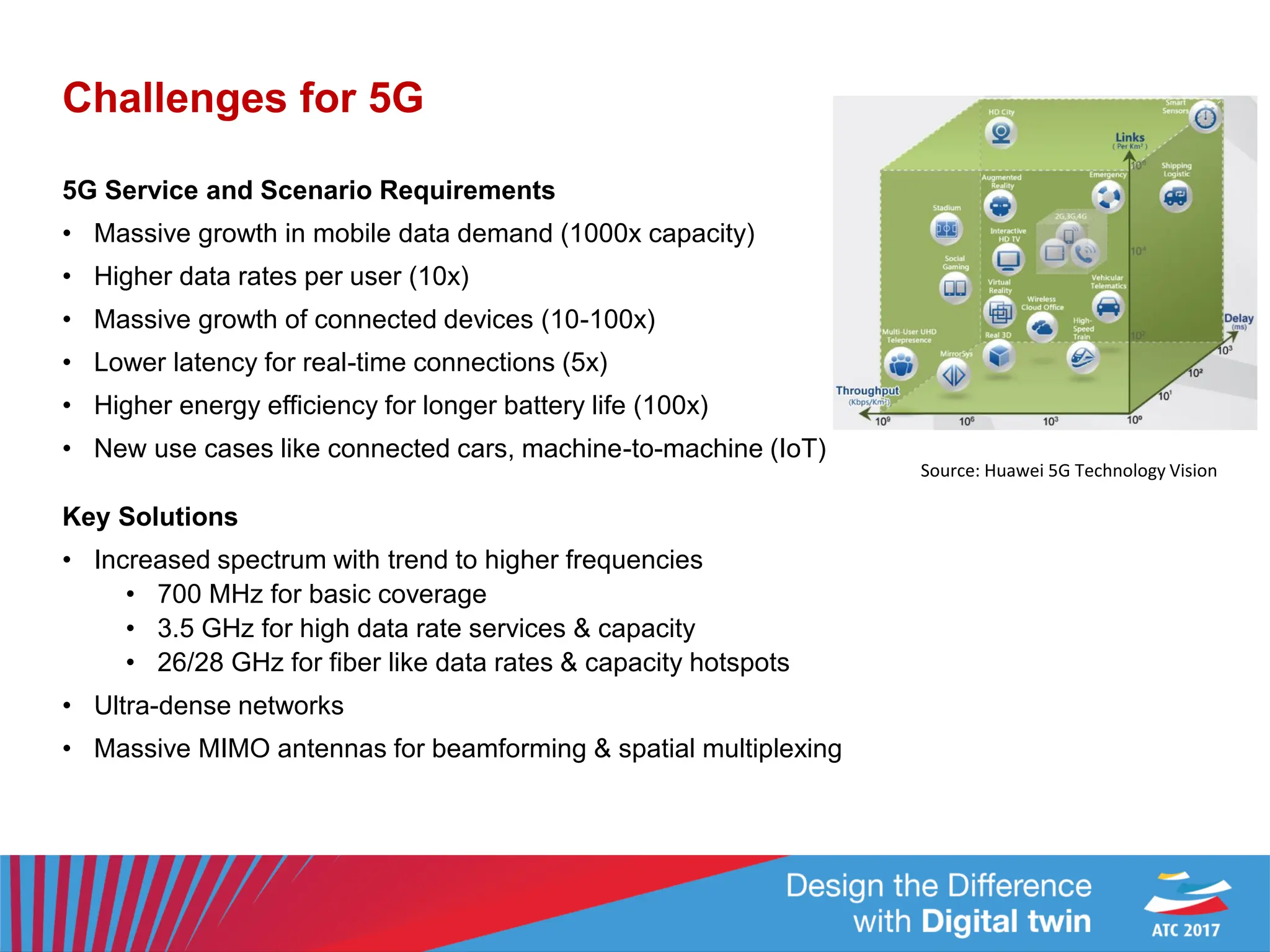
5G networks will require 1000x capacity increases to support new applications like connected cars. This document discusses challenges like designing high gain antennas for mobile devices and base stations operating at 26GHz. Optimization tools were used to design dual MIMO arrays for phones and large planar arrays for base stations. Radio channel analysis using 3D ray tracing showed path loss increases and angular spreads decrease at 26GHz. Network planning tools can simulate dense urban coverage for different spectrum bands and antenna configurations to guide 5G deployment strategies.
![Array Design
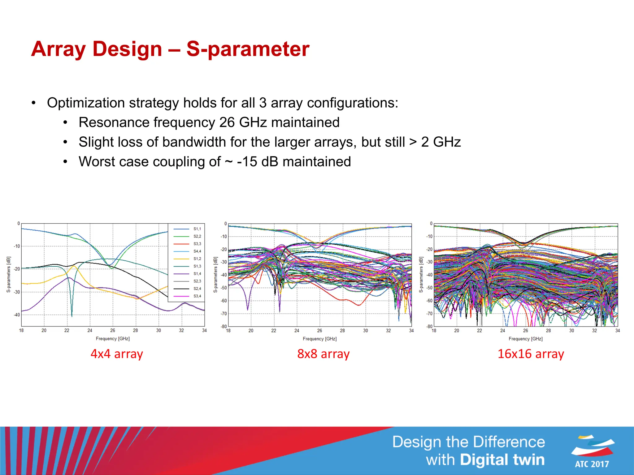
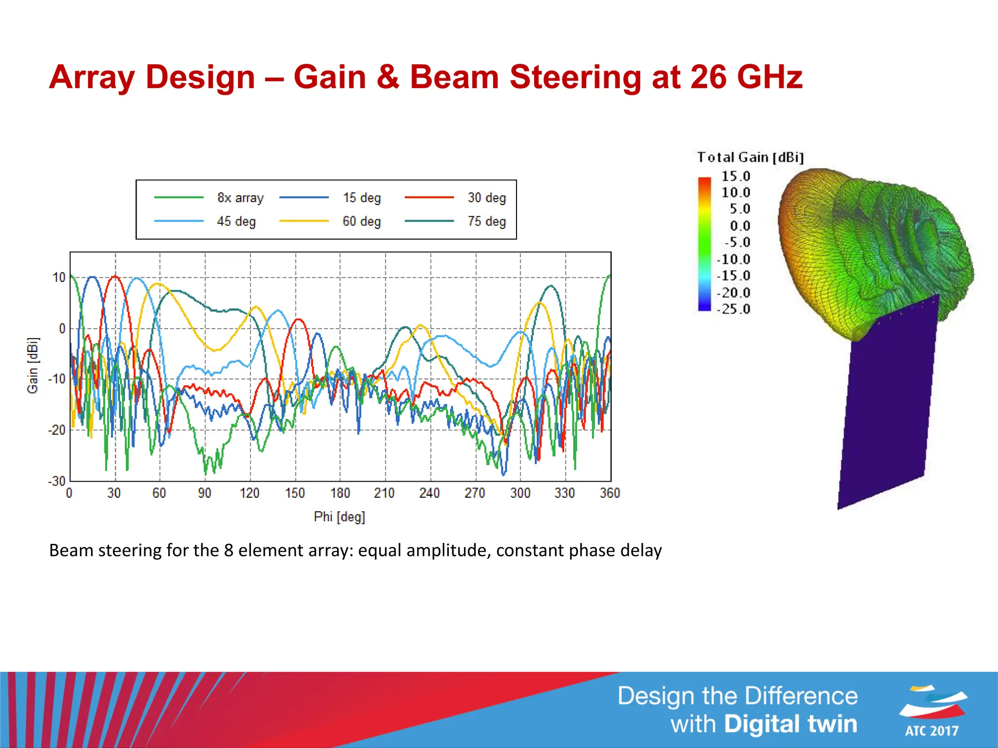
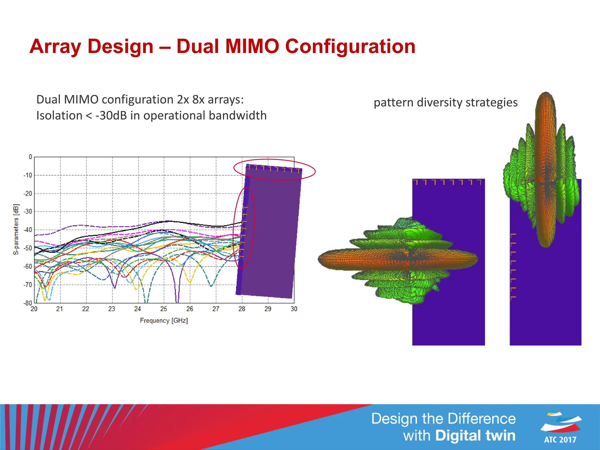
• Design based on [1] re-optimized for 24-28 GHz band
• WB dipole antenna element in linear 8x array
• Printed, Rogers RT5880 substrate
• Optimization with 5x frequency points
• 8 geometric parameters considered
• Snn & Smn optimization goals
• Optimized with FEKOs GRSM method
• Optimized geometry integrated into PCB
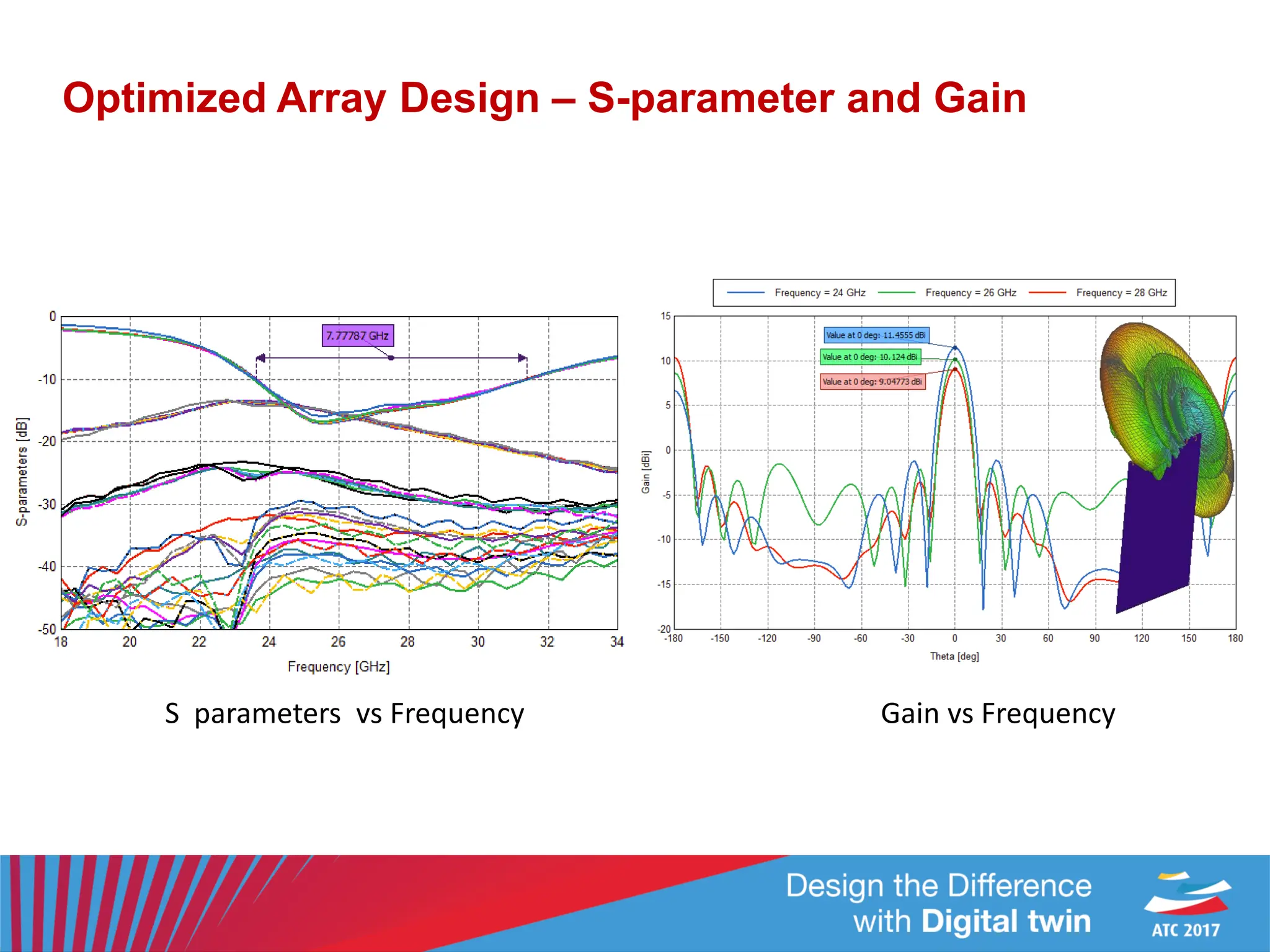
• Simulated with FDTD for full S-parameter and far-field characterization
[1] UWB mm-Wave Antenna Array with Quasi Omnidirectional Beams
for 5G Handheld Devices - N. Parchin, et. al, ICUWB 2016
optimization model
integrated into PCB
single element](https://image.slidesharecdn.com/atc20175g-antenna-design-and-network-planningjaehoon-kim-231209011351-387b613d/75/ATC2017_5G-Antenna-Design-and-Network-Planning_Jaehoon-Kim-pdf-6-2048.jpg)
![Array Design
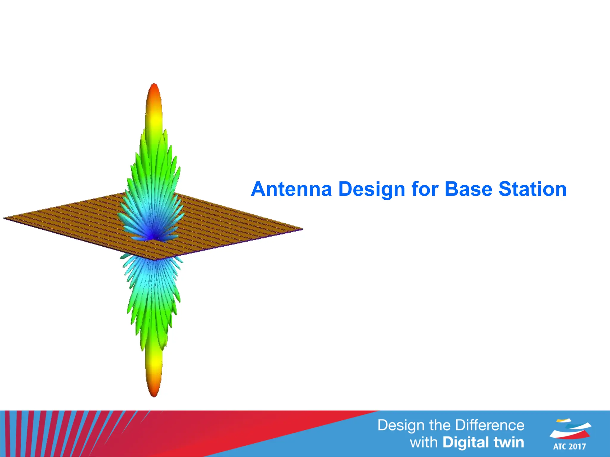
• Design based on [1] (designed to operate in 22 GHz band) – re-optimized for 26 GHz band
• Loop design, including slot to increase efficiency
• Printed, low cost, FR4 substrate
initial optimization
base element
optimization model
2x2 array 4x4 array 8x8 array 16x16 array
[1] 8×8 Planar Phased Array Antenna with High Efficiency and Insensitivity
Properties for 5G Mobile Base Stations - N. Parchin, et. al, EUCAP 2016](https://image.slidesharecdn.com/atc20175g-antenna-design-and-network-planningjaehoon-kim-231209011351-387b613d/75/ATC2017_5G-Antenna-Design-and-Network-Planning_Jaehoon-Kim-pdf-13-2048.jpg)