This document summarizes the design of a MIMO 1x8 antenna operating at 38 GHz for future 5G applications. The antenna array uses an RT/duroid 5880 substrate with 0.787 mm thickness and 2.2 dielectric constant. Simulation results show the 1x8 element antenna achieves 13.4 dBi gain and -15.76 dB return loss within a 1.294 GHz bandwidth from 37.485 to 38.779 GHz. Increasing the number of antenna elements from 1x4 to 1x8 improves the gain but maintains similar radiation patterns, meeting the gain requirements for 5G.
![TELKOMNIKA, Vol.16, No.2, April 2018, pp. 600~605
ISSN: 1693-6930, accredited Aby DIKTI, Decree No: 58/DIKTI/Kep/2013
DOI:10.12928/TELKOMNIKA.v16i2.8383 600
Received December 18, 2017; Revised January 18, 2018; Accepted February 1, 2018
Design MIMO 1x8 Antenna for Future 5G Applications
Yusnita Rahayu, Muhammad Rifqy Asrul*, Tulus Rahayu
Department of Electrical Engineering, Faculty of Engineering, Universitas Riau,
Pekanbaru, Riau, Indonesia
*Corresponding author, e-mail: muhammad.rifqyasrul@student.unri.ac.id
Abstract
This paper presented the design of MIMO 1x8 antenna operating at 38 GHz for future 5G
applications.The antenna used the Rogers RT / duroid 5880 substrate with a thickness of 0.787 mm and a
dielectric constant of 2.2. This antenna has 1x8 elements with 13.4 dBi of gain and the return loss of -
15.76 dB. It has approximately 1.294 GHz bandwidth within the range of 37.485 GHz-38.779 GHz. The
comparison performances between both antennas MIMO 1x4 and 1x8 are also discussed. It is shown that
both radiation patterns are similar. The increasing number of elements affect to the gain and frequency.
The proposed antenna meets the 5G requirements.
Keywords:MIMO, antenna,38 GHz, 5G application
Copyright © 2018 Universitas Ahmad Dahlan. All rights reserved.
1. Introduction
The fifth generation (5G) wireless communications will expand application scenarios in
the future. These scenarios and the need for enhanced mobile broadband applications require
higher demands [1]. The next generation wireless networks (5G) target to provide 1000 times
higher wireless area capacity in 2020 compared to the one in 2010. To boost the capacity in the
spectral domain, the millimeter wave (mm-wave) communication is a promising solution by
exploring the huge bandwidth at higher frequency [2, 4]. However, because of the high path loss
as well as high sensitivity, there are a lot of challenges in 5G communication. Antenna, as one
of the key components in the system, has been widely investigated, mainly including massive
MIMO and millimeter-wave antennas [3].
In the past two decades, planar antennas have attracted interest for millimeter-wave
phased arrays because of their features of wide bandwidth, low cost, ease of fabrication, and
high-efficiency. Several types of planar antennas have been developed for phased array
systems [4].
In 5G requirements, the antenna should at least have a gain of 12 dBi and bandwidth
more than 1 GHz [5]. A compact wideband feeding technology is employed to feed a patch
array antenna. High-gain and wide bandwidth can be achieved at the same time [6]. An array
technique as conventional way in antenna design is used to prove high gain performance as
described in paper [7]. This paper proposes the design of 5G antenna for 38 GHz. The antenna
uses RT Duroid 5880 with thickness (h) of 0.787 mm, dielectric constant of 2.2, loss tangent of
0.0009 and 50 Ω of impedance. The dimension of the substrate is 5x6 mm. The structure of this
paper as follows: starting with the introduction then followed by the antenna design and analysis
in next section for single element, 1x4 element and 1x8 element. Last, all the results are
concluded in conclusion section.
2. Antenna Design and Result Analysis
2.1. Single Element
The geometry of single element antenna is shown in Figure 1 and optimized parameters
for the proposed antenna is shown in Table 1. The geometry of this antenna was derived
from [5] with some modifications.](https://image.slidesharecdn.com/178383-200821075917/75/Design-MIMO-1x8-Antenna-for-Future-5G-Applications-1-2048.jpg)


![ ISSN: 1693-6930
TELKOMNIKA Vol. 16, No. 2, April 2018: 600 – 605
604
Figure 9. The simulated radiation pattern of 1x4 elements antenna 2D and 3D model
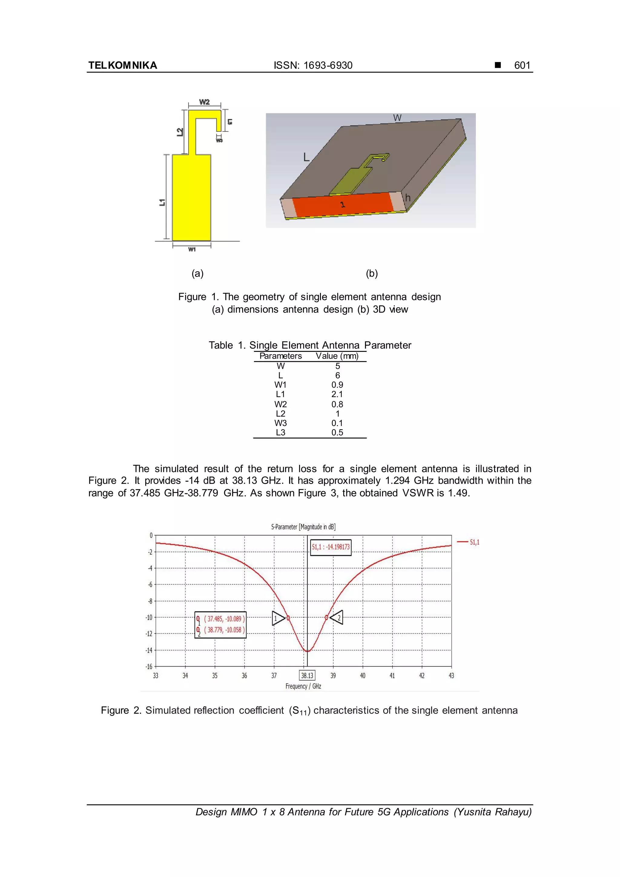
3.2. MIMO 1x8 Antenna
Figure 10 shows the design of MIMO antenna with 8 elements. Simulated S-parameters
of the array is illustrated in Figure 11. From the result, the simulated return loss of -15.76 dB is
obtained. There is an increase in return loss compared to 4 elements. The isolations between
the consecutive ports, S21, S32, S43 etc.are well below -20dB which show a lesser mutual
coupling between them.
The simulated radiation pattern is presented in Figure 12. It was observed when
elements were assembled in the form of eight element antenna linear array, there was an
increase in antenna gain from 10.5 dBi to 13.9 dBi with side lobe level is -6.9 dB. Refer to [5],
antenna with gain of 9 dBi, it can work at MIMO.
Figure 10. The geometry of 1x8 elements antenna design
Figure 11. Simulated reflection coefficient (S11) characteristics of the 1x8 elements antenna](https://image.slidesharecdn.com/178383-200821075917/75/Design-MIMO-1x8-Antenna-for-Future-5G-Applications-5-2048.jpg)
![TELKOMNIKA ISSN: 1693-6930
Design MIMO 1 x 8 Antenna for Future 5G Applications (Yusnita Rahayu)
605
Figure 12. The simulated radiation pattern of 1x8 elements antenna 2D and 3D model
4. Conclusion
This paper presents the MIMO antenna with 4 and 8 elements for future 5G
applications. From the simulation results, it is shown that by increasing the number of elements
of antenna affect to the gain and return loss. Antenna with 8 elements has 13.4 dBi of gain with
the return loss of -15.76 dB. While antenna with 4 elements, the gain obtained is 10.5 dBi with
return loss of -16.381 dB. The radiation patterns for both configurations are similar. It has
approximately 1.294 GHz bandwidth within the range of 37.485 GHz–38.779 GHz.
References
[1] Jae-Joon P, Jinyi L, Juyul L, Heon-Kook K, Myung-Don K, Bonghyuk P. Urban Microcellular
EnvironmentBased on 28 and 28 GHz Measurements. Proc. IEEE Annual International Symposium
on Personal, Indoor, and Mobile Radio Communications (PIMRC). 2016; 4: 1-5.
[2] Waleed A, Wasif TK. Small Form Factor Dual Band (28/38 GHz) PIFA Antenna for 5G Applications.
Proc. IEEE MTT-S International Conference on Microwaves for Intelligent Mobility (ICMIM). 2017: 21-
24.
[3] Son XT, Hosung C, Ikmo P. Broadband Printed-Dipole Antenna and Its Arrays for 5G Applications.
IEEE Antennas and Wireless Propagation Letters. 2017; 16: 2183-2186.
[4] Naser OP, Ming S, Gert Frolund P. End-Fire Phased Array 5G Antenna Design Using Leaf-Shaped
Bow-Tie Elements for 28/38 GHz MIMO Applications. Proc. IEEE International Conference on
Ubiquitous Wireless Broadband (ICUWB). 2016: 1-4.
[5] Mohammed AS, Talal S, Ramadhan A. Design of Efficient Microstrip Liniear Array for 5G
Communication Systems. Proc. IEEE. 2017, 43-47.
[6] Yusnita R, Razali N, Tharek AR. Various Slotted UWB Antenna Design. Proc. International
Conference on Wireless and Mobile Communications. 2010: 107-110.
[7] AF Morabito, AR Laganà, T Isernia. “Isophoric array antennas with a low number of control points: a
„size tapered‟ solution”. Progress in Electromagnetics Research Letters. 2013; 36: 121-131.](https://image.slidesharecdn.com/178383-200821075917/75/Design-MIMO-1x8-Antenna-for-Future-5G-Applications-6-2048.jpg)


![YTD Video Downloader Pro 7.6.2.1 Full Crack [Latest] 2025](https://cdn.slidesharecdn.com/ss_thumbnails/finalreviewpresentationmimoantenna-250417041757-40684f67-250418050101-49458d80-thumbnail.jpg?width=640&height=640&fit=bounds)