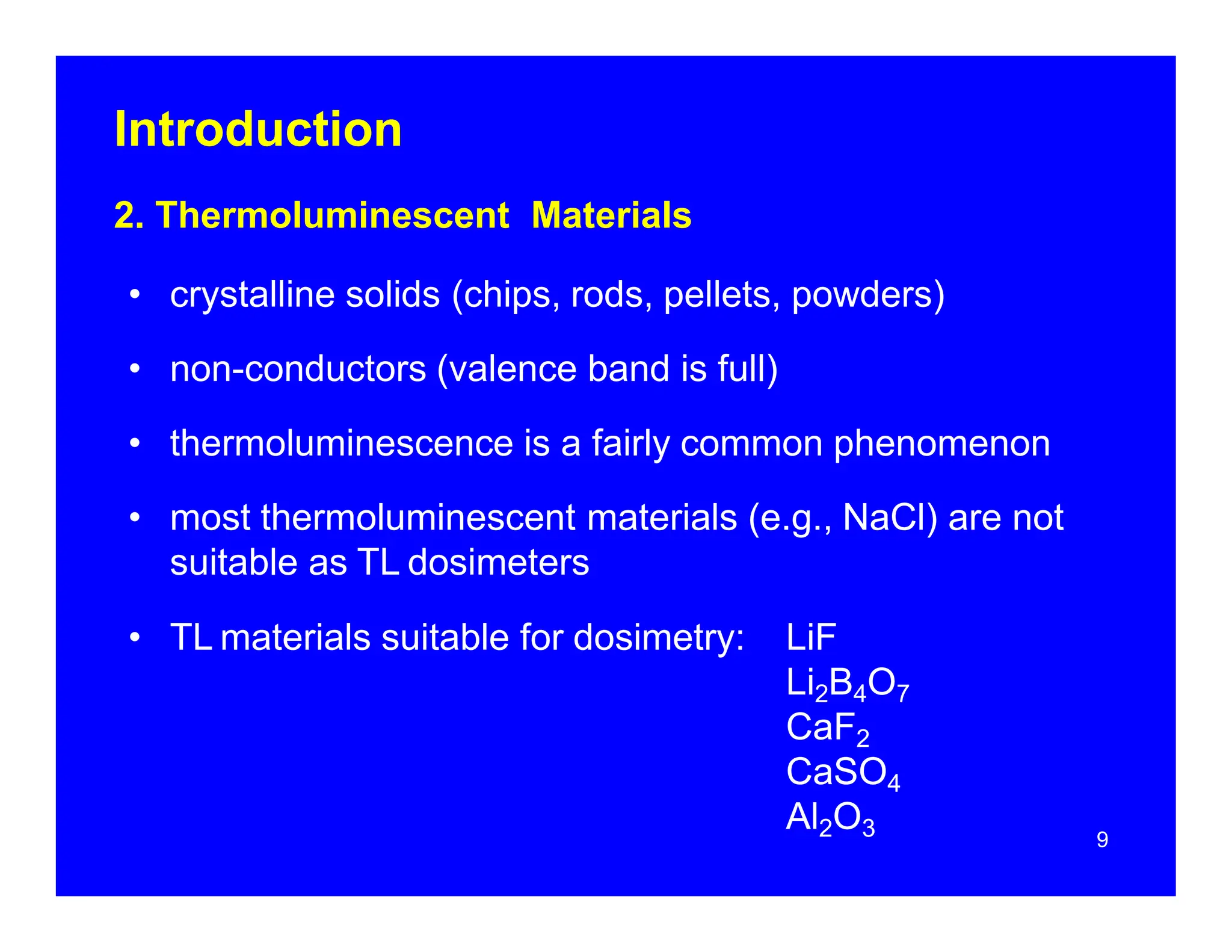
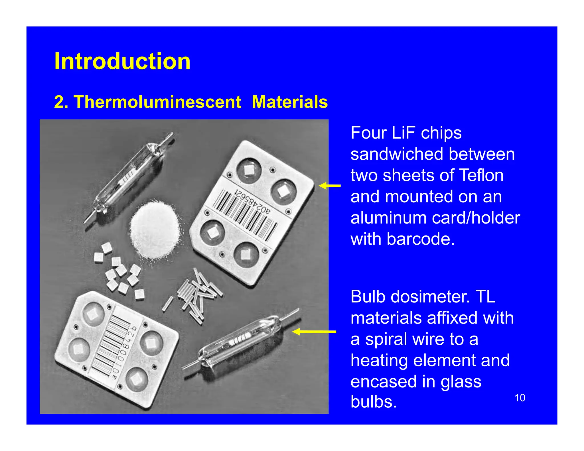
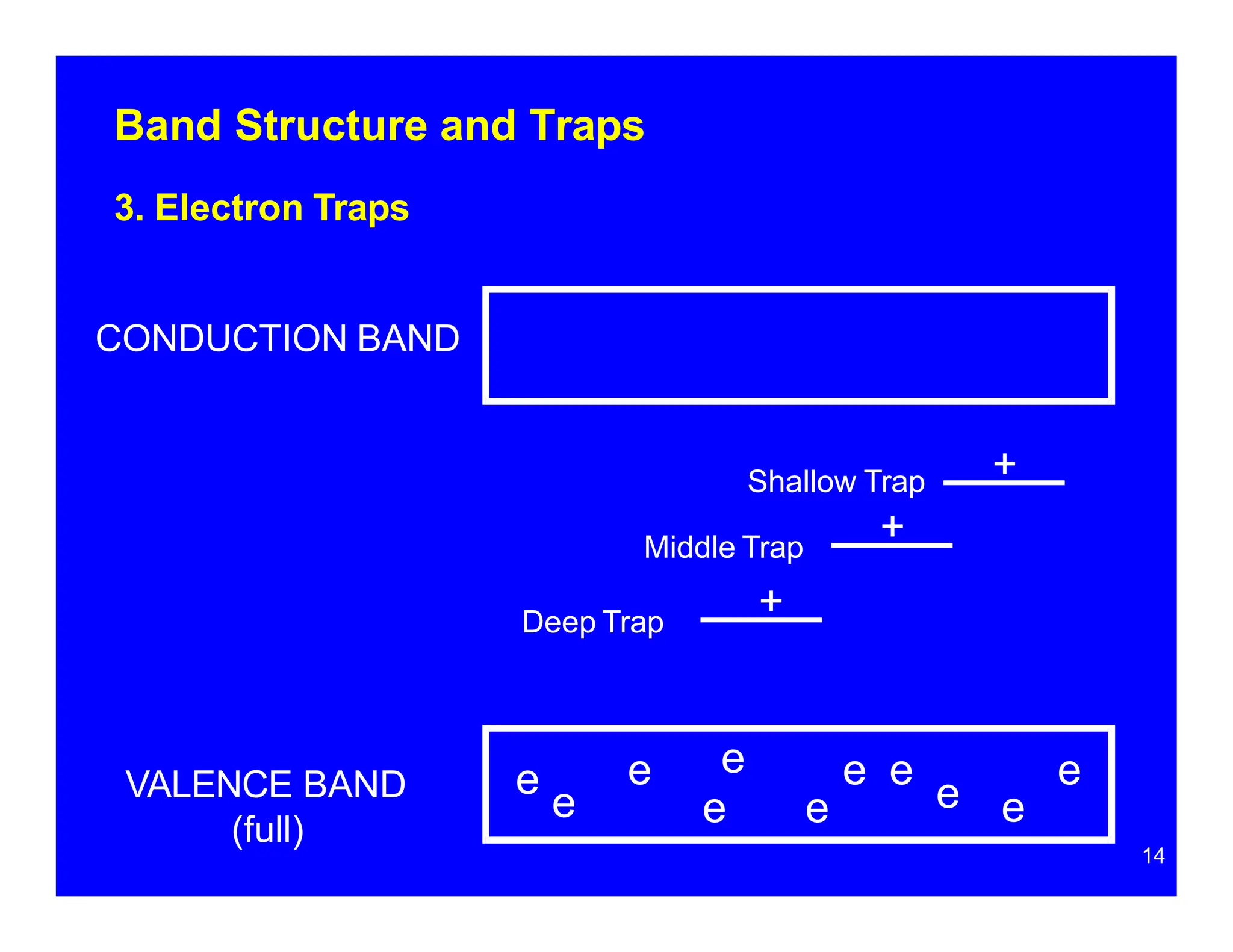
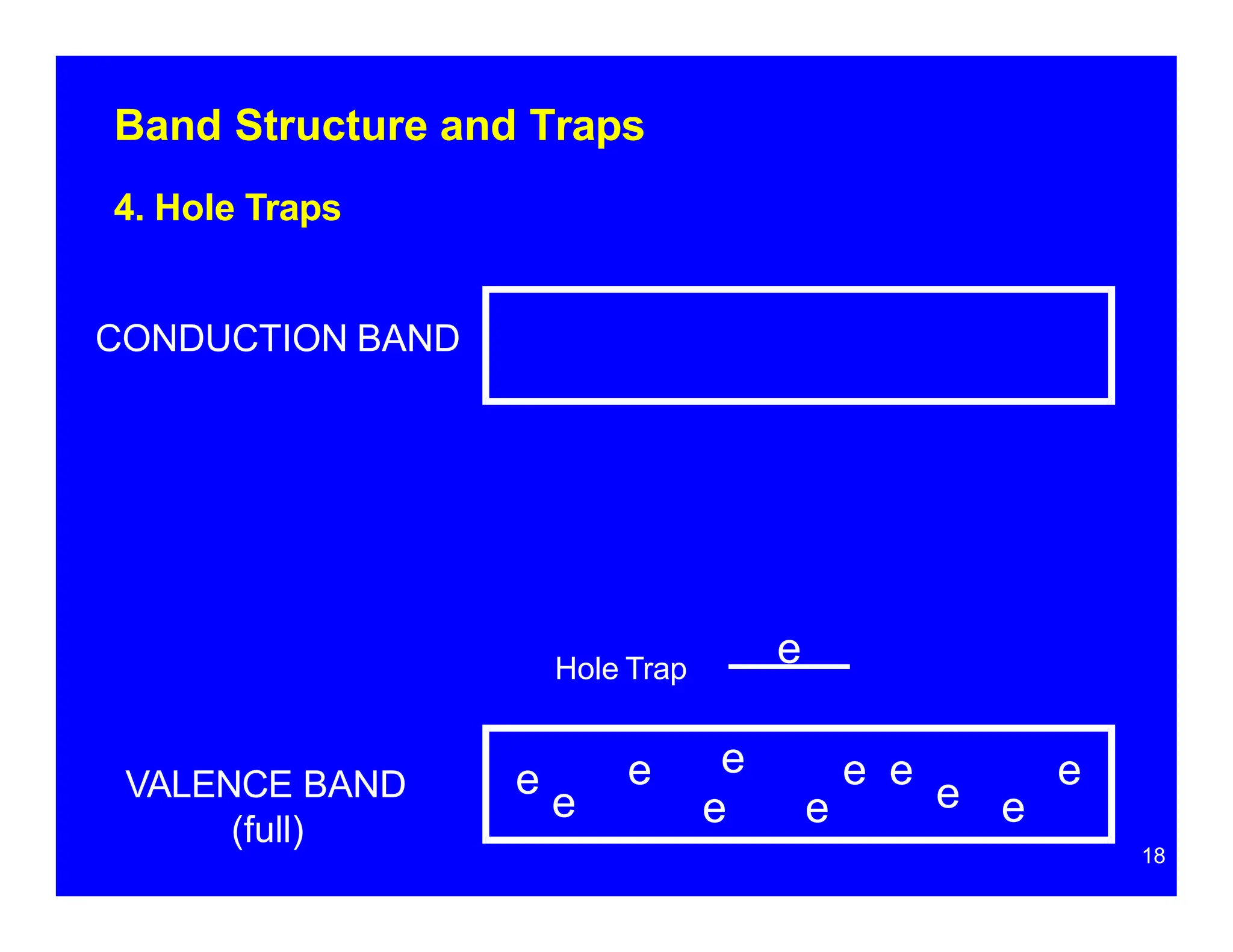
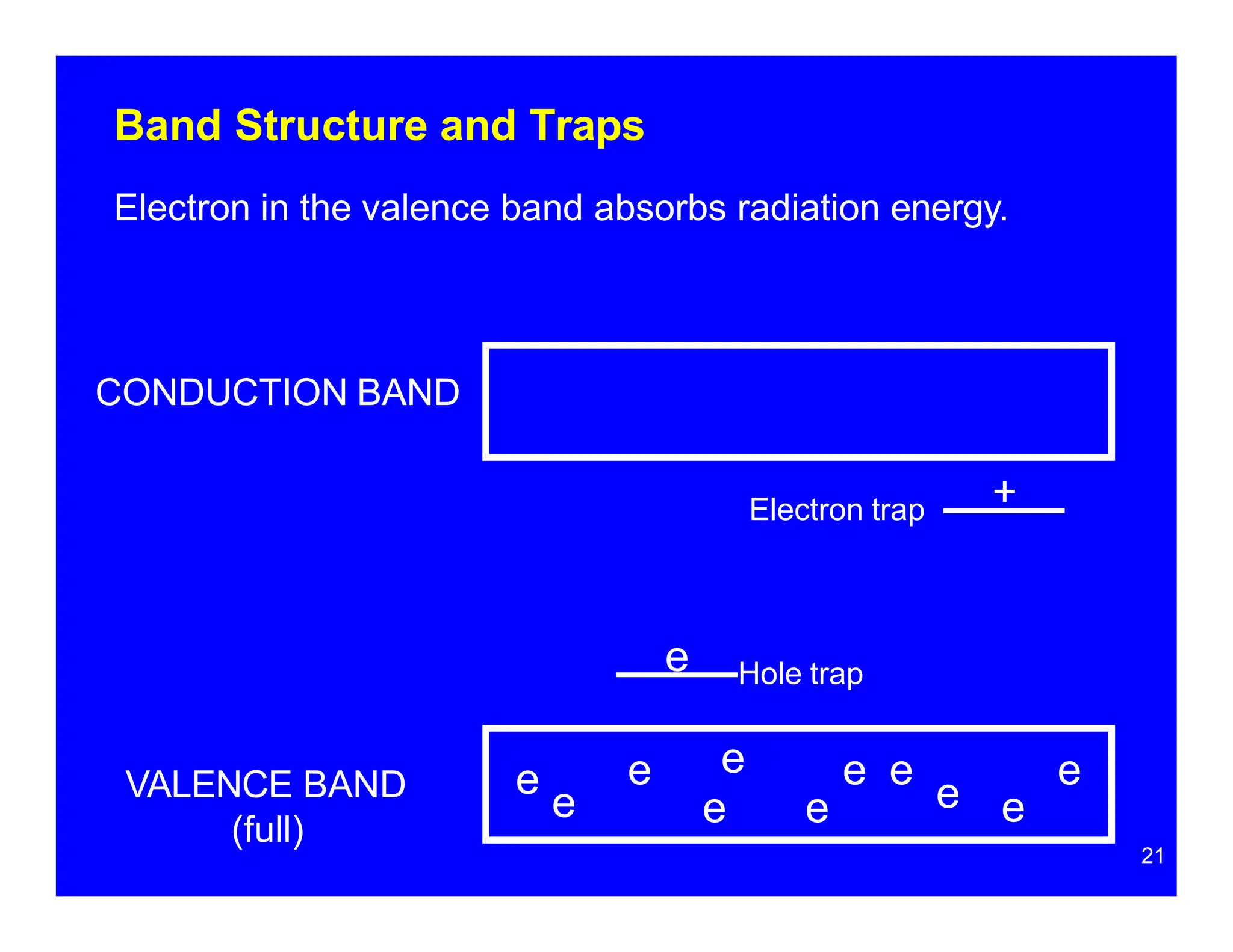
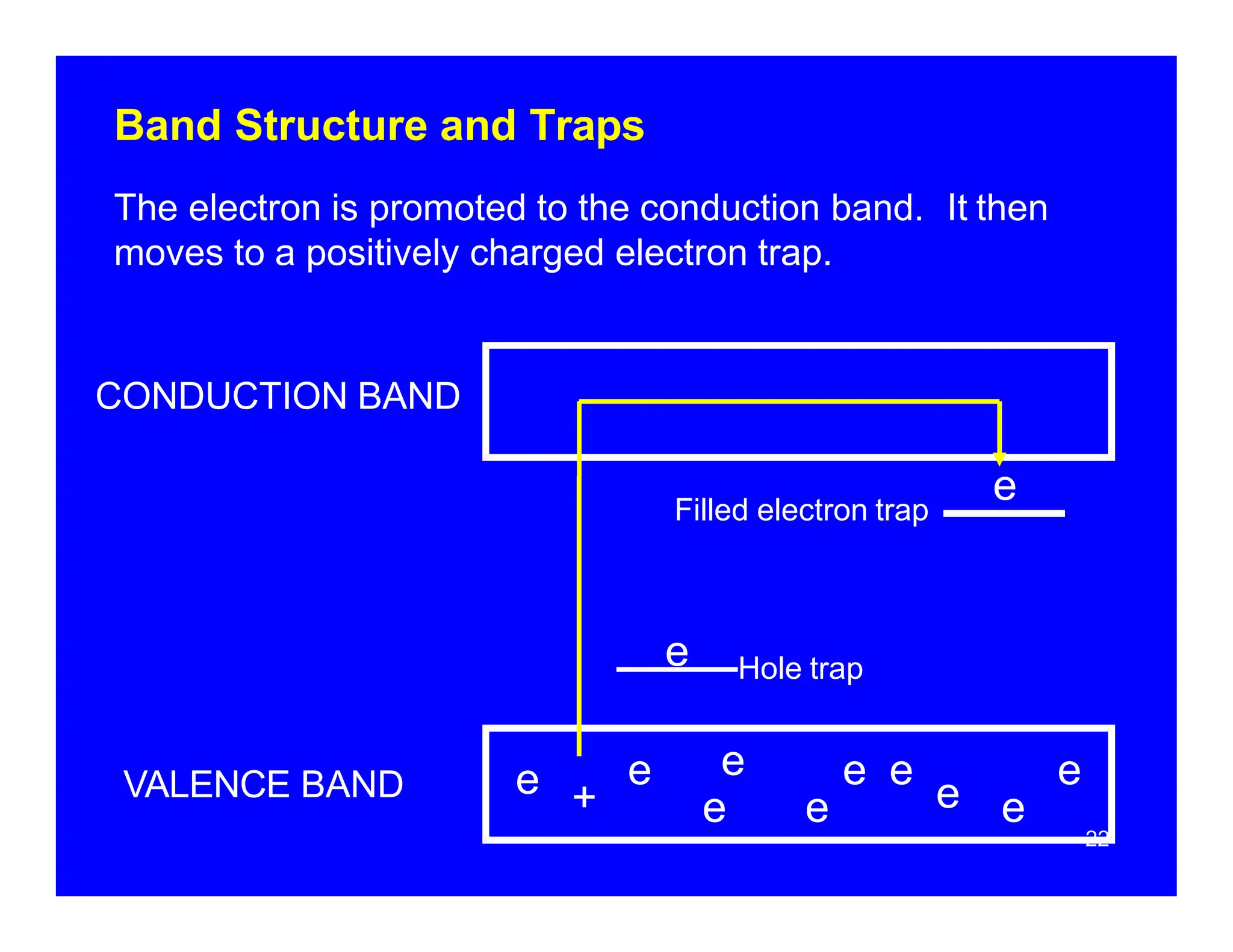
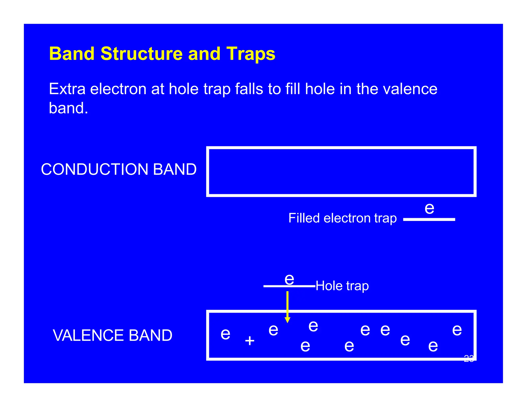
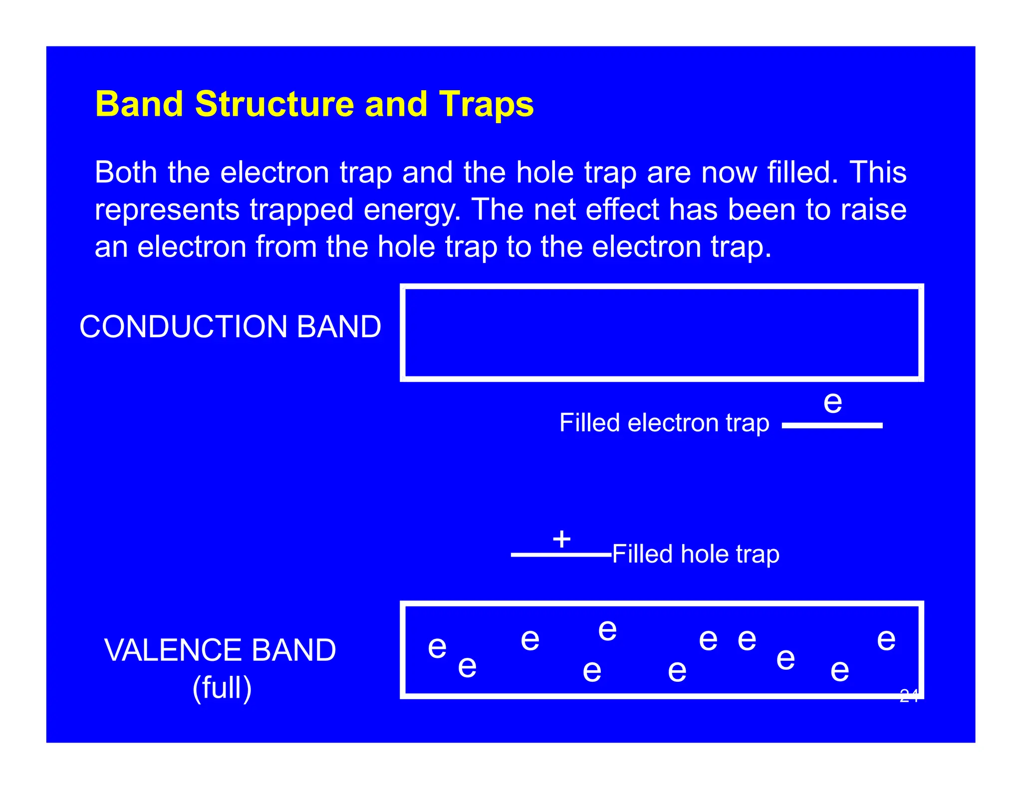
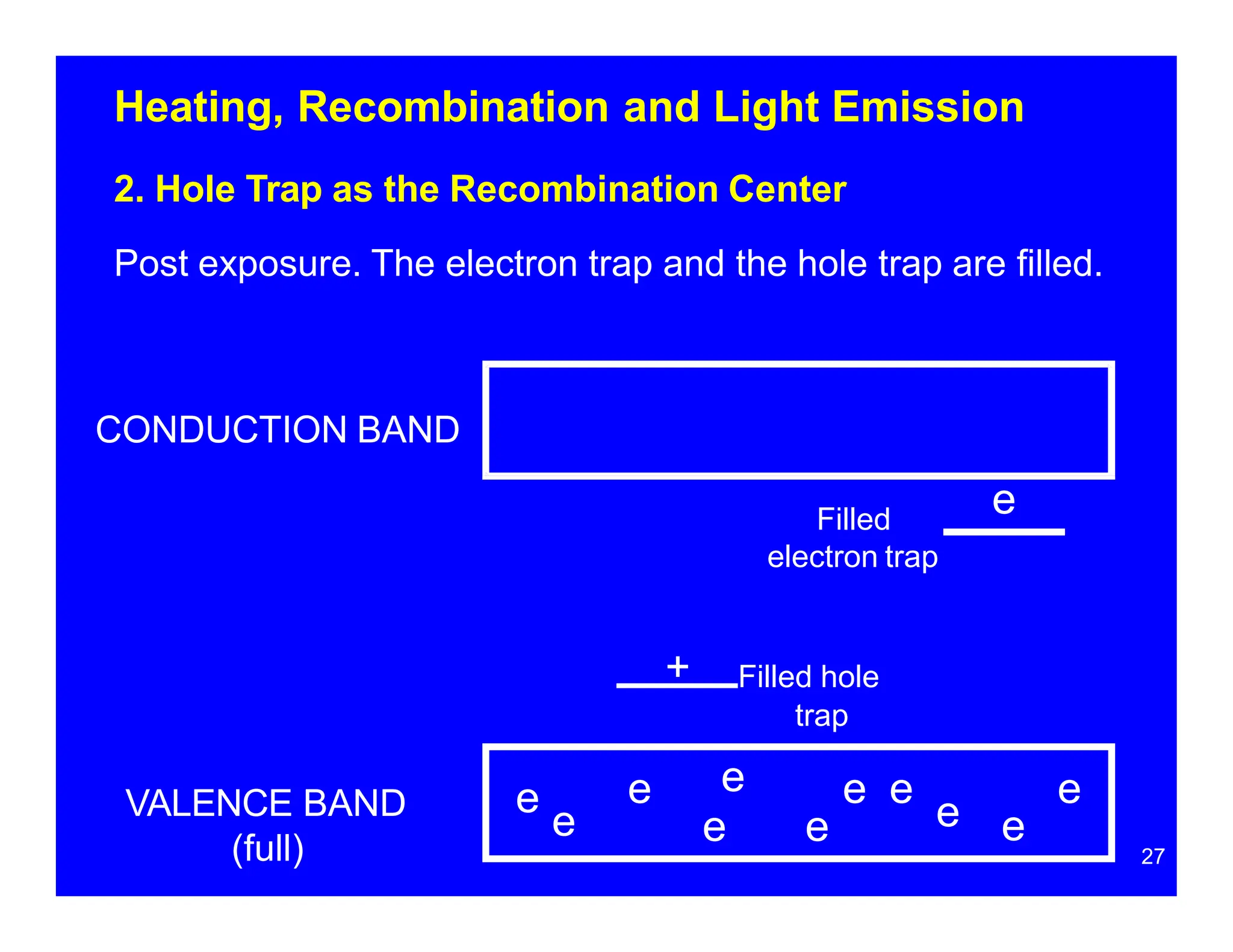
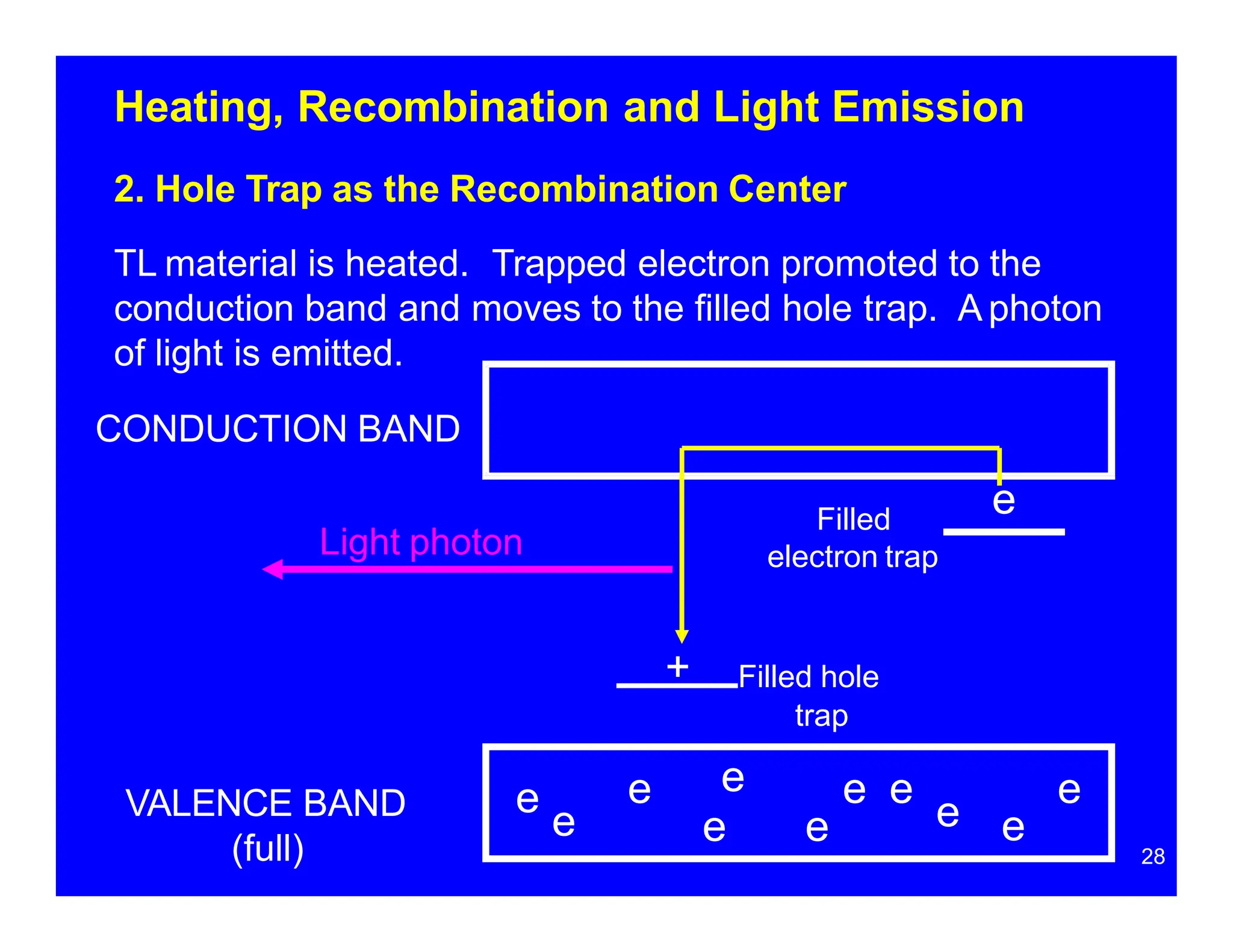
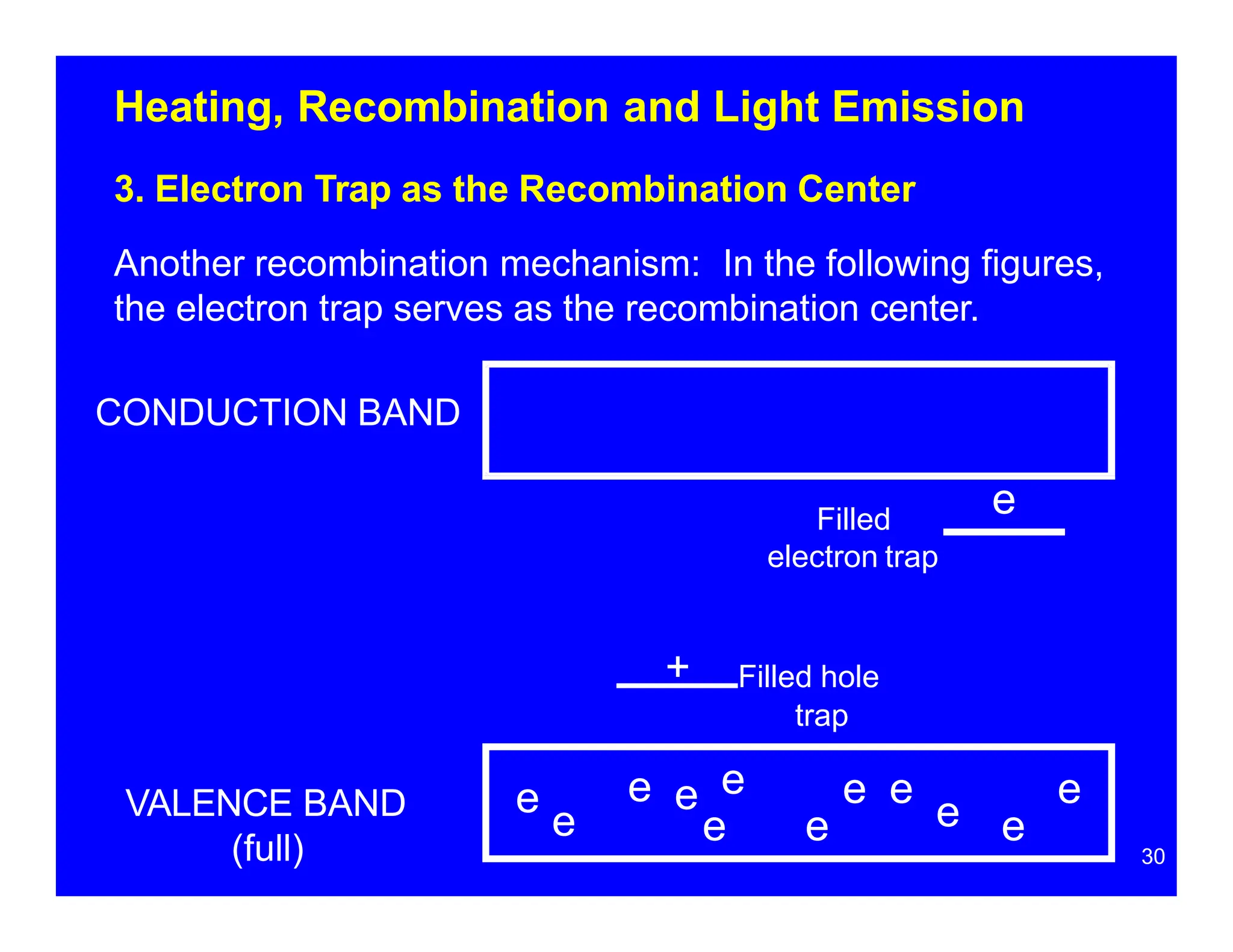
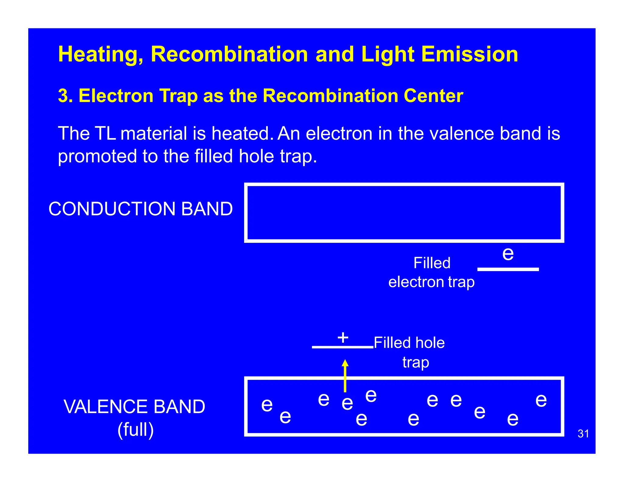
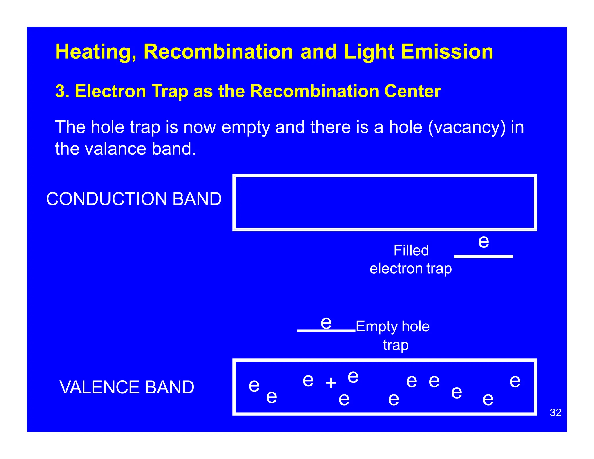
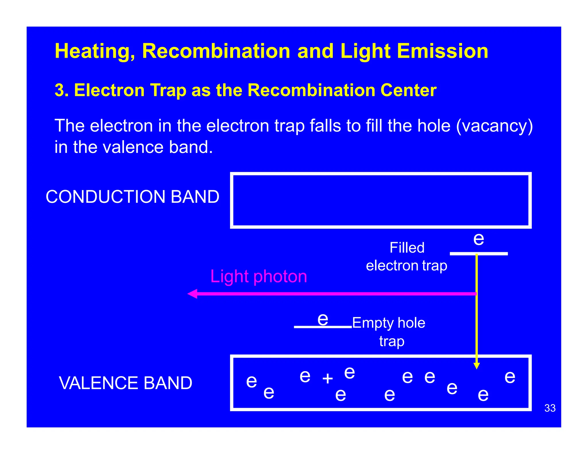
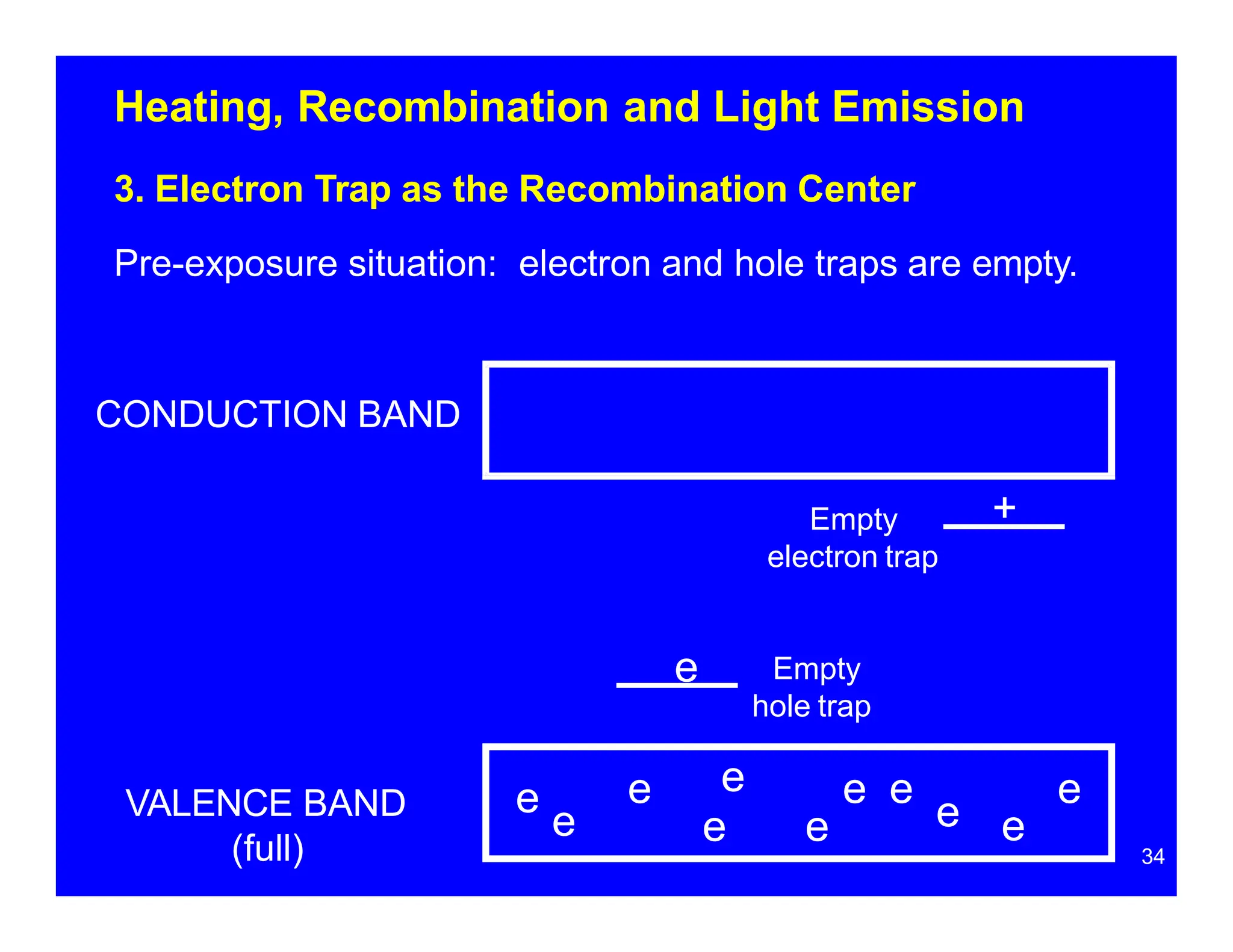
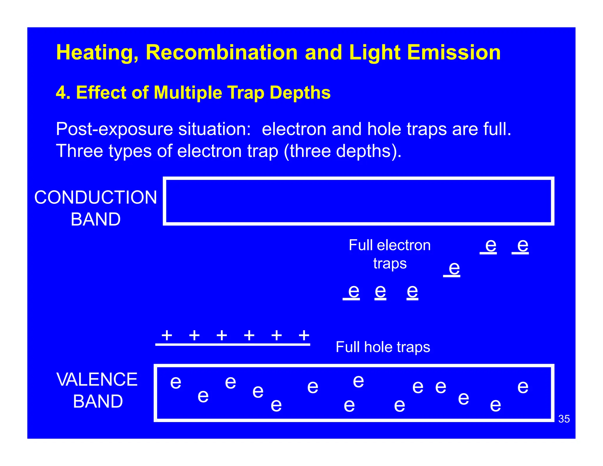
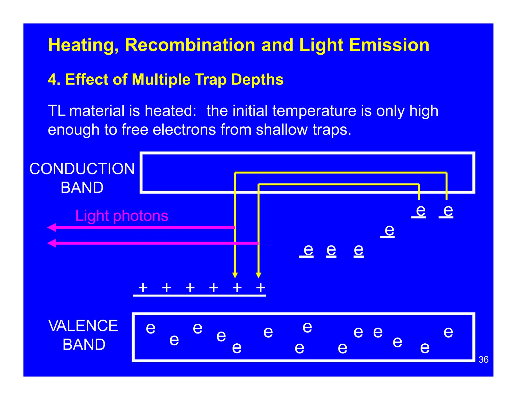
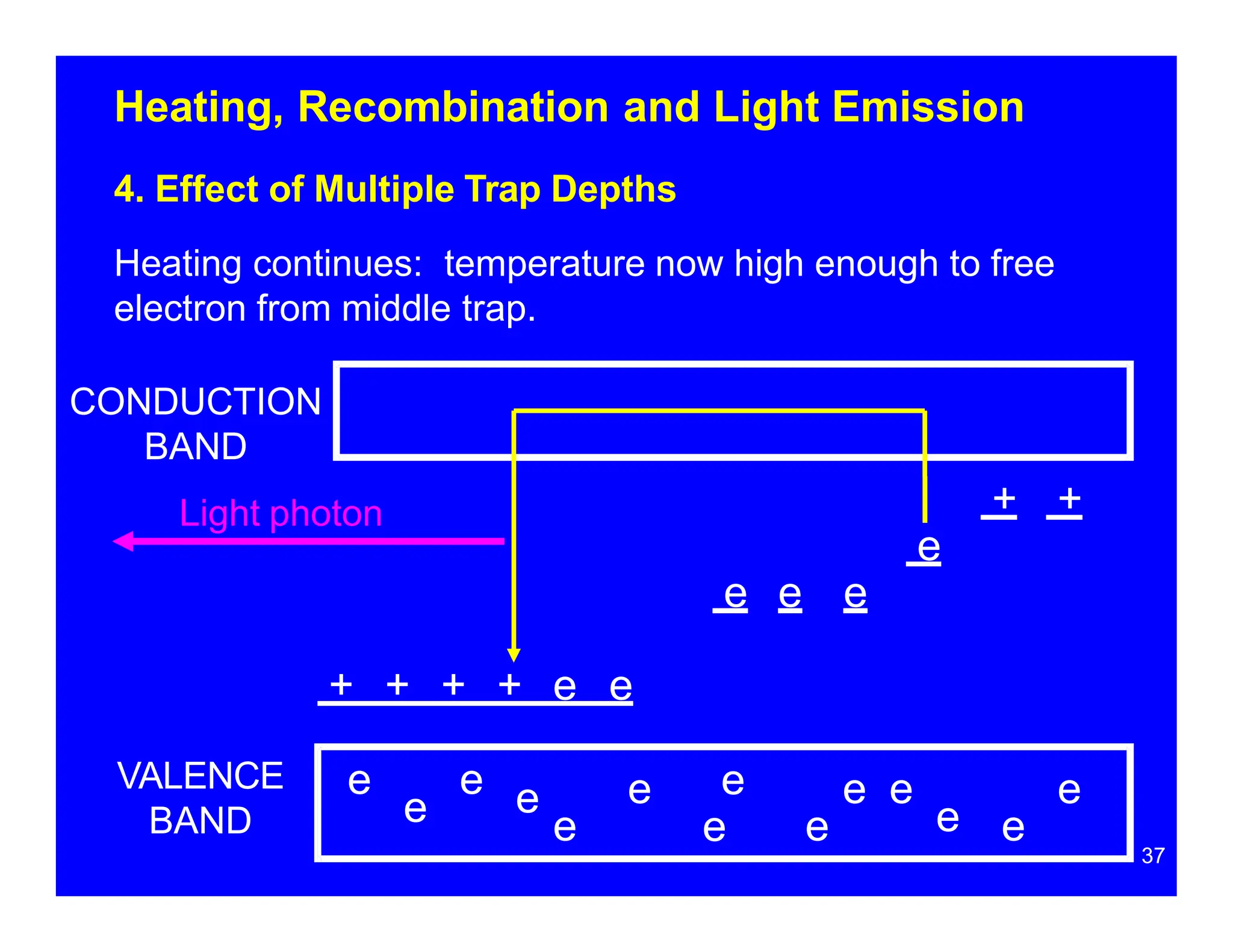
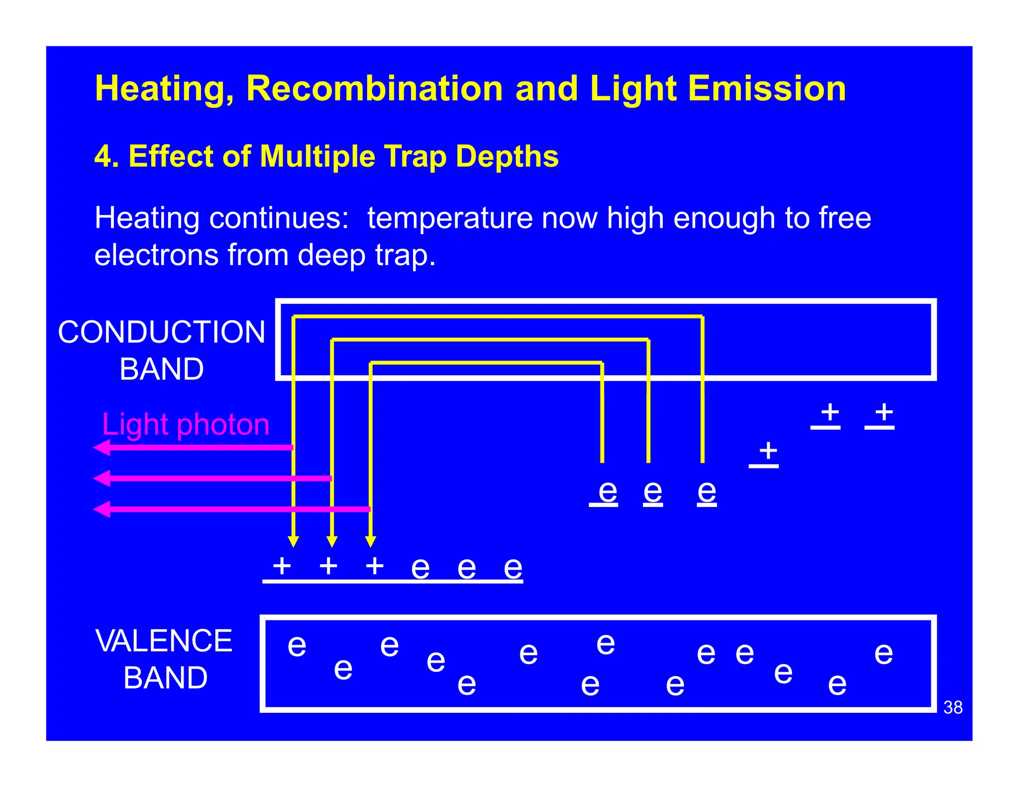
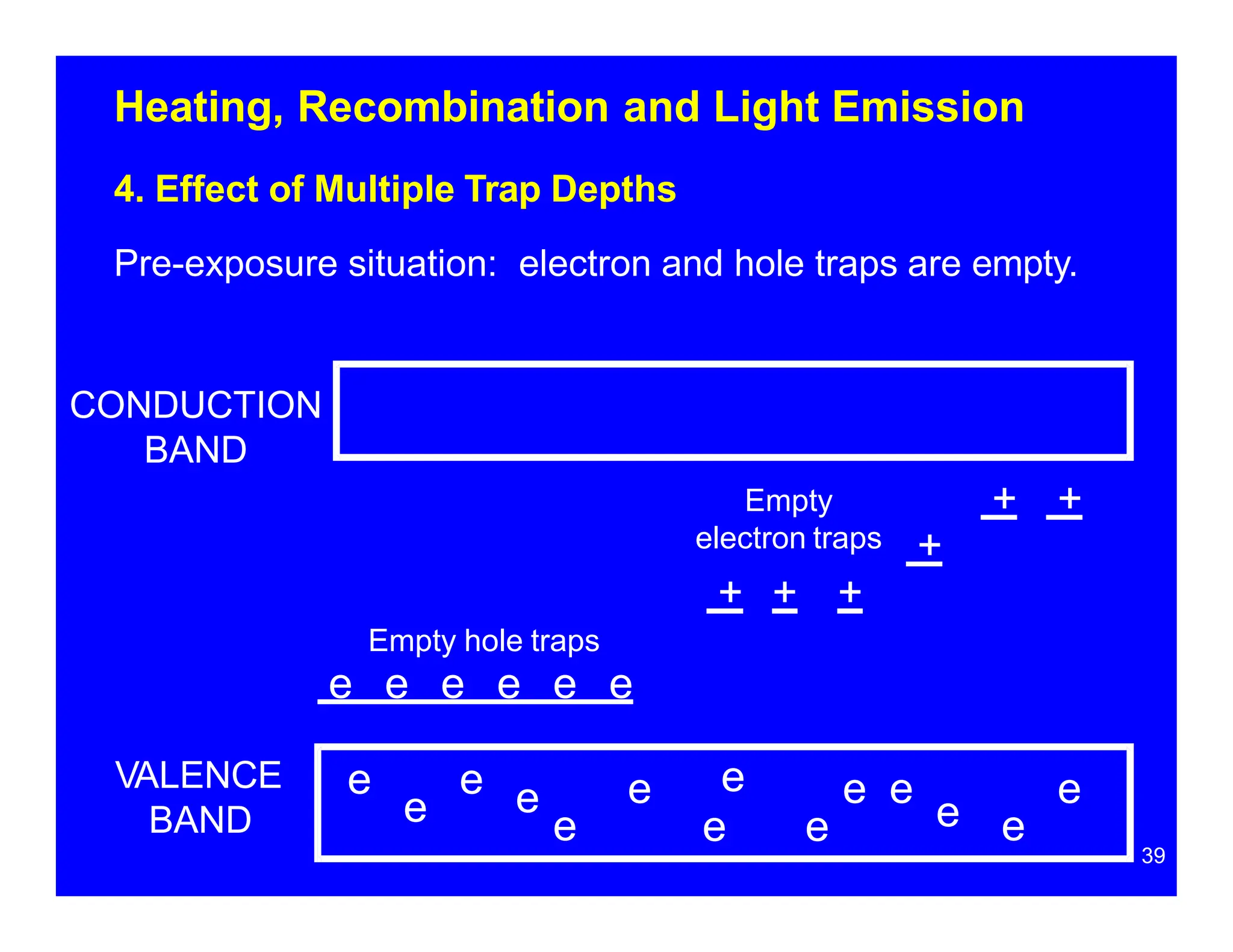
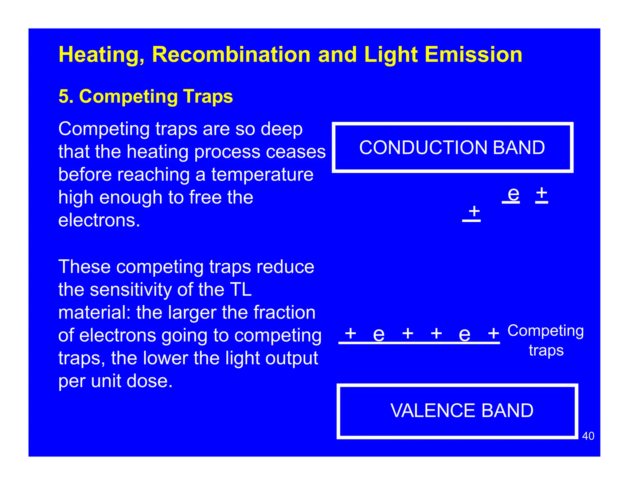
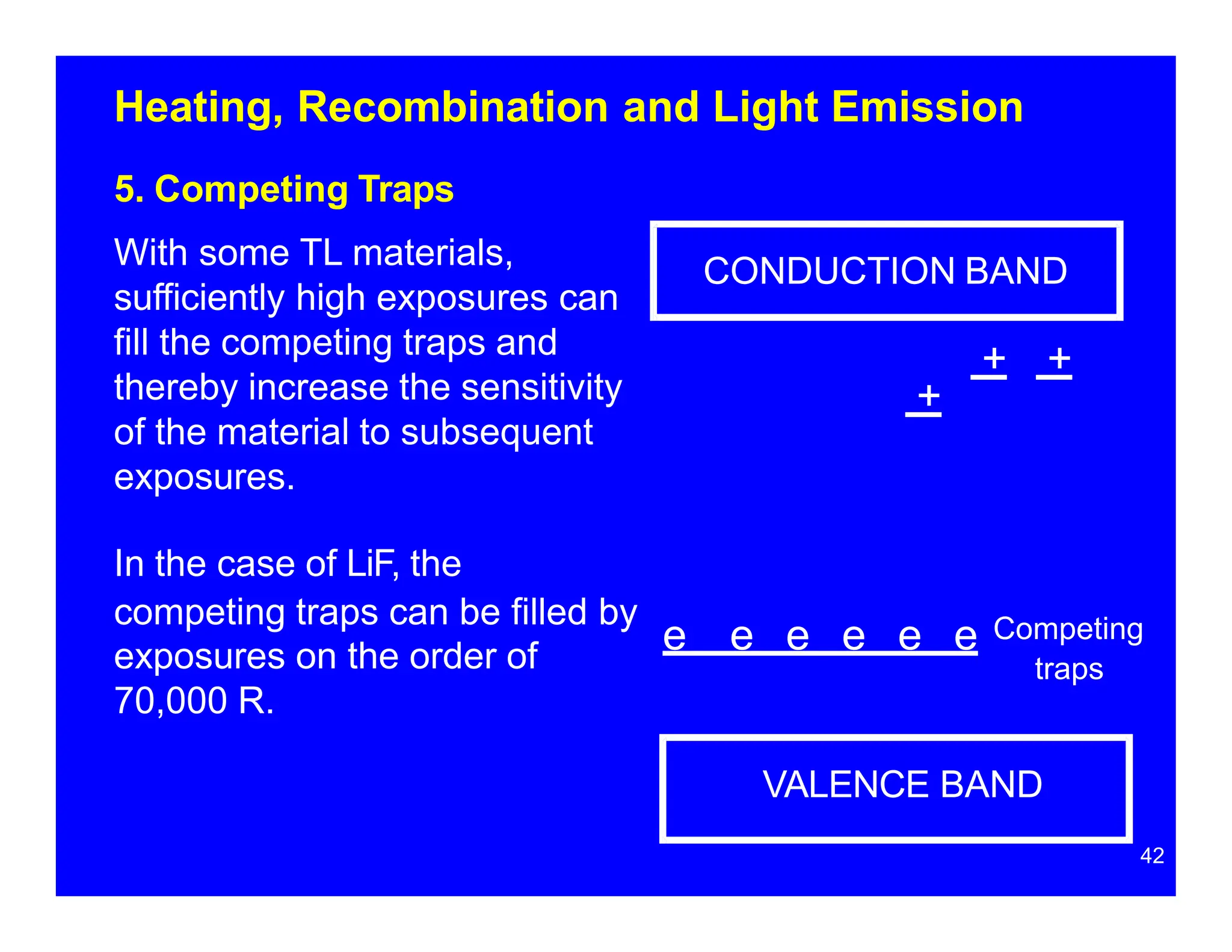
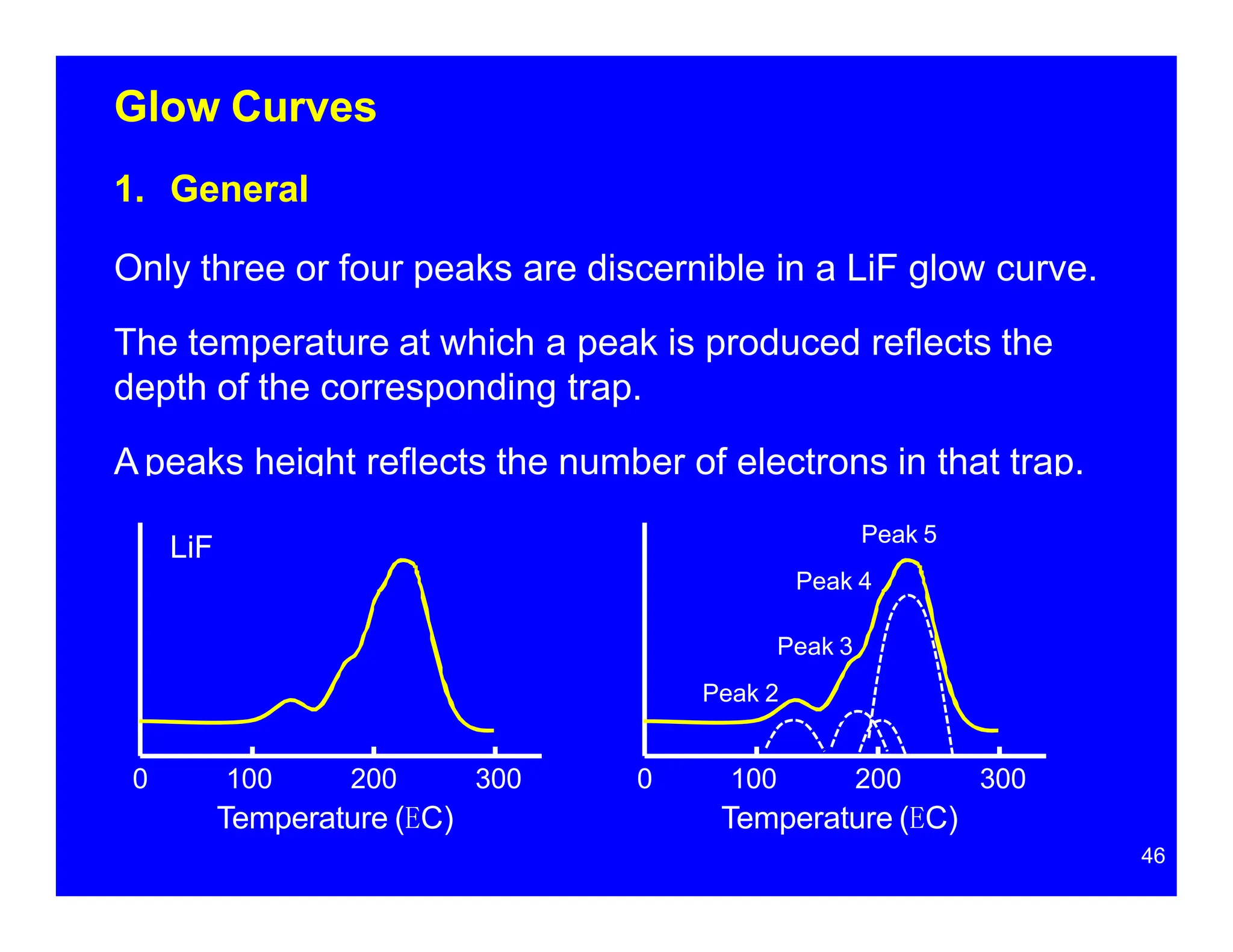
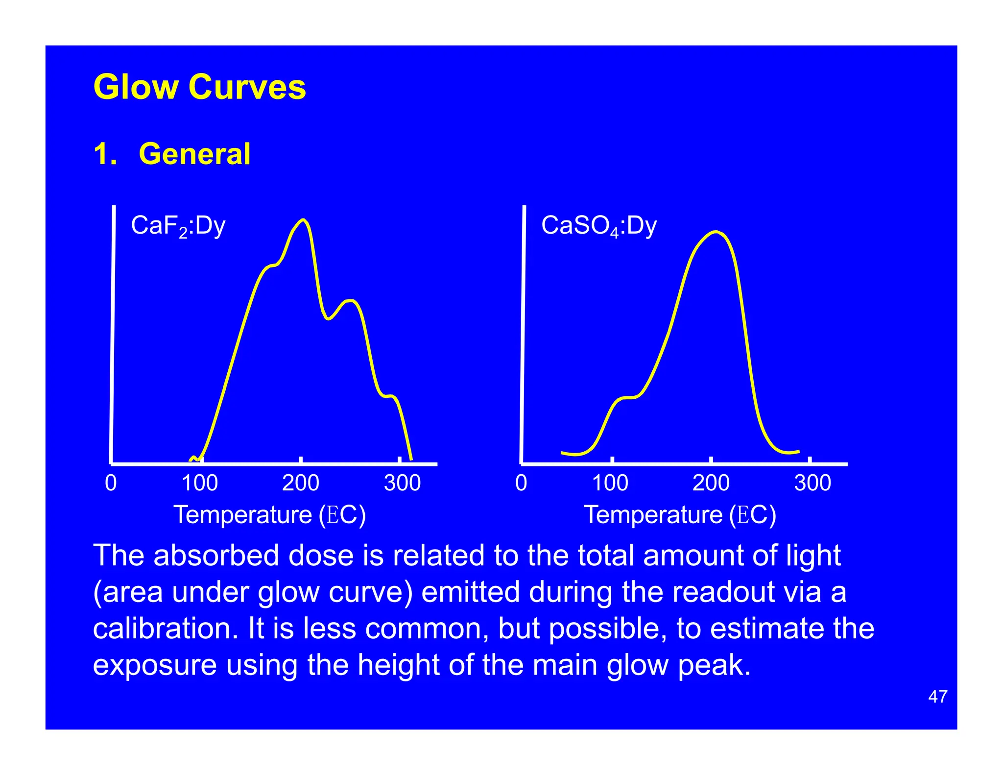
SlideShare a Scribd company logo
1 of 100
Thermoluminescent
Dosimeters
1
3/1/2011
Contents
Introduction
1. General
2. Thermoluminescent Materials
Band Structure and Traps
1. General
2. Electron and Hole Traps
3. Electron Traps
4. Hole Traps
5. EnergyAbsorption and Trapping
2
Contents
Heating, Recombination and Light Emission
1. General
2. Hole Traps as the Recombination Center
3. Electron Traps as the Recombination Center
4. Effect of Multiple Trap Depths
5. Competing Traps
Glow Curves
1. General
2. Things that can Affect the Glow Curve Shape
3. Handling and Cleaning TL Materials
4. UV Sensitivity
3
Contents
TLD Readers
1. General
2. Nitrogen Quenching
3. Contact Heating Element
4. Heated N2 Gas
5. Infrared lamp Heater
Heating, Annealing and Readout
1. Annealing
2. Readout
3. Ramp Rate
4. Heat Cycle
4
Contents
5
TL Material Characteristics
1. Fading
2. Sensitivity
3. Energy Response
4. Supralinearity
5. Emission Spectrum
Neutron Dosimetry
1. General
2. Harshaw TLDs
3. Li-6 and Li-7
4. Li2B4O7 and CaSO4
5. LiF Glow Curve
6. Albedo Dosimeters
Appendix: Correction Factors and Algorithms
Introduction
6
Introduction
1. General
When scintillators (e.g., NaI, ZnS) absorb energy imparted by
ionizing radiation, they immediately release some of this
energy as light. For each particle of radiation interacting with
the scintillator, a flash of light (scintillation) is produced. The
greater the energy absorbed by the material, the brighter the
flash.
When thermoluminescent materials (e.g., LiF) absorb energy,
much of this energy is trapped rather than released
immediately. The material must be heated for this trapped
energy to be released as light.
7
Introduction
1. General
The total amount of light emitted during the heating process
reflects the absorbed dose (i.e., the radiation energy
absorbed).
The emitted light can’t be used to determine the energy
deposited by individual particles of radiation. It reflects the
total energy deposited by all the radiation interactions in the
TL material.
8
Introduction
9
2. Thermoluminescent Materials
• crystalline solids (chips, rods, pellets, powders)
• non-conductors (valence band is full)
• thermoluminescence is a fairly common phenomenon
• most thermoluminescent materials (e.g., NaCl) are not
suitable as TL dosimeters
• TL materials suitable for dosimetry: LiF
Li2B4O7
CaF2
CaSO4
Al2O3
Introduction
10
2. Thermoluminescent Materials
Four LiF chips
sandwiched between
two sheets of Teflon
and mounted on an
aluminum card/holder
with barcode.
Bulb dosimeter. TL
materials affixed with
a spiral wire to a
heating element and
encased in glass
bulbs.
11
Band Structure
and Traps
Band Structure and Traps
1. General
All materials contain impurities and defects.
When impurities are added intentionally to a TL material, the
latter is said to be "doped."
The added impurities are referred to as activators. The
identity of the activator might appear in parentheses after the
formula for the TL material, e.g., LiF(Mg), or following a
colon, e.g., LiF:Mg.
Electrons located at these impurities may possess energies
that electrons in other parts of the solid cannot, i.e., they may
possess energies in the band gap.
12
Band Structure and Traps
2. Electron and Hole Traps
Two types of impurities: electron traps
hole traps
Electron traps are impurities with insufficient electrons to
complete covalent bonds with the surrounding atoms.
Until filled by an electron, there is a hole at the electron trap.
In the following figures, the hole is symbolized with a + sign.
TL materials have a specific number of traps, e.g., LiF is
said to have 11 or 12 traps. The idea is that the material
has a specific number of different types of impurities.
Electrons at these impurities possess energies at different
levels (depths) in the band gap.
13
Band Structure and Traps
3. Electron Traps
CONDUCTION BAND
VALENCE BAND
(full)
14
Shallow Trap +
+
e
e
e
e
e e
e
e e
e e
Middle Trap
Deep Trap
+
Band Structure and Traps
3. Electron Traps
The main electron trap of LiF (the trap that accumulates the
most electrons) is believed to be produced by a magnesium
trimer.
Magnesium is a natural impurity in LiF and is ordinarily
found at a concentration of 175 ppm.
15
Band Structure and Traps
4. Hole Traps
Hole traps are impurities with more unpaired electrons than
needed to form covalent bonds with the surrounding atoms.
In the case of LiF, the main hole trap is believed to be a
Ti(OH)n complex. Like magnesium, titanium is an natural
impurity in LiF. The titanium concentration is believed to be
on the order of 10 ppm.
The extra electrons at such impurities are more loosely
bound than those forming covalent bonds. Their energies
are also higher, just above those in the valence band.
16
Band Structure and Traps
4. Hole Traps
Hole traps are impurities with more unpaired electrons than
needed to form covalent bonds with the surrounding atoms.
In the case of LiF, the main hole trap is believed to be a
Ti(OH)n complex. Like magnesium, titanium is an natural
impurity in LiF. The titanium concentration is believed to be
on the order of 10 ppm.
The extra electrons at such impurities are more loosely
bound than those forming covalent bonds. Their energies
are also higher, just above those in the valence band.
17
Band Structure and Traps
4. Hole Traps
CONDUCTION BAND
VALENCE BAND
(full)
18
e
e
e
e
e e
e
e e
e e
Hole Trap
e
Band Structure and Traps
5. Energy Absorption and Trapping
When radiation interacts with a TL material, energy is
transferred to electrons. Some of these electrons absorb
sufficient energy to be promoted from the valence band to
the conduction band.
Once in the conduction band, the electrons are mobile and
some will move to the electron traps.
At an electron trap (now filled), the electrons possess more
energy than they did before the radiation interaction.
19
Band Structure and Traps
5. Energy Absorption and Trapping
Electrons at the empty hole traps fall to fill the holes created
in the valence band.
In effect, the holes have moved from the valence band to
the hole traps. the latter are now filled. This leaves the hole
trap filled.
Some of the electron traps and hole traps are now filled.
This represents trapped energy.
20
CONDUCTION BAND
Band Structure and Traps
Electron in the valence band absorbs radiation energy.
VALENCE BAND
(full)
21
Electron trap +
e Hole trap
e
e
e
e
e e
e
e e
e e
Band Structure and Traps
VALENCE BAND
Filled electron trap
e e e
22
e Hole trap
The electron is promoted to the conduction band. It then
moves to a positively charged electron trap.
CONDUCTION BAND
e
e e e
+
e e e
e
Band Structure and Traps
VALENCE BAND
Filled electron trap
e Hole trap
Extra electron at hole trap falls to fill hole in the valence
band.
CONDUCTION BAND
e
e e e
23
e e e
e e e
e
+
Band Structure and Traps
24
Filled electron trap
+ Filled hole trap
Both the electron trap and the hole trap are now filled. This
represents trapped energy. The net effect has been to raise
an electron from the hole trap to the electron trap.
CONDUCTION BAND
e
e
e
e
e
e e
e
e e
e e
VALENCE BAND
(full)
25
Heating,
Recombination and
Light Emission
Heating, Recombination and Light Emission
26
1. General
Upon heating, many of the trapped electrons and holes will
recombine at what are known as recombination centers.
This recombination results in the emission of light.
When heating promotes a trapped electron into the
conduction band, the electron moves to a filled hole trap. In
this case, the hole trap is the recombination center.
The recombination involves the electron falling from the
conduction band to a lower energy at the filled hole trap. In
most cases this results in the emission of a photon whose
wavelength is on the order of 300-600 nm.
Heating, Recombination and Light Emission
2. Hole Trap as the Recombination Center
Post exposure. The electron trap and the hole trap are filled.
CONDUCTION BAND
27
Filled
electron trap
+ Filled hole
trap
e
e
e
e
e
e e
e
e e
e e
VALENCE BAND
(full)
Heating, Recombination and Light Emission
2. Hole Trap as the Recombination Center
TL material is heated. Trapped electron promoted to the
conduction band and moves to the filled hole trap. A photon
of light is emitted.
CONDUCTION BAND
28
e
e
e
e
e
e e
e
e e
e e
VALENCE BAND
(full)
+ Filled hole
trap
Filled
electron trap
Light photon
Heating, Recombination and Light Emission
2. Hole Trap as the Recombination Center
The pre-exposure situation: electron and hole traps are
empty. The electrons are in the lowest possible energy state.
CONDUCTION BAND
29
+
e
e
e
e
e
e e
e
e e
e e
VALENCE BAND
(full)
Empty
hole trap
Empty
electron trap
Heating, Recombination and Light Emission
3. Electron Trap as the Recombination Center
Another recombination mechanism: In the following figures,
the electron trap serves as the recombination center.
CONDUCTION BAND
30
Filled
electron trap
+ Filled hole
trap
e
e
e
e
e
e e
e
e e
VALENCE BAND
(full)
e e e
Heating, Recombination and Light Emission
3. Electron Trap as the Recombination Center
The TL material is heated. An electron in the valence band is
promoted to the filled hole trap.
CONDUCTION BAND
31
Filled
electron trap
+ Filled hole
trap
e
e
e
e
e
e e
e
e e e
VALENCE BAND
(full)
e e
Heating, Recombination and Light Emission
3. Electron Trap as the Recombination Center
The hole trap is now empty and there is a hole (vacancy) in
the valance band.
CONDUCTION BAND
Filled
electron trap
e e e
32
e
e
e
e
e e
e
e + e
e Empty hole
trap
VALENCE BAND
Heating, Recombination and Light Emission
3. Electron Trap as the Recombination Center
The electron in the electron trap falls to fill the hole (vacancy)
in the valence band.
CONDUCTION BAND
Filled
electron trap
e
e
e
e
e e
e
e + e
e Empty hole
trap
VALENCE BAND
Light photon
e e e
33
Heating, Recombination and Light Emission
3. Electron Trap as the Recombination Center
Pre-exposure situation: electron and hole traps are empty.
CONDUCTION BAND
34
+
e
e
e
e
e
e e
e
e e
e e
VALENCE BAND
(full)
Empty
hole trap
Empty
electron trap
Heating, Recombination and Light Emission
4. Effect of Multiple Trap Depths
Post-exposure situation: electron and hole traps are full.
Three types of electron trap (three depths).
CONDUCTION
BAND
e
35
e
e
e
e e
e
e e
e e
VALENCE
BAND e
e e
e
e e
+ + + + + +
Full electron
traps
e e e
Full hole traps
Heating, Recombination and Light Emission
4. Effect of Multiple Trap Depths
TL material is heated: the initial temperature is only high
enough to free electrons from shallow traps.
e
e
e
e
e e
e
e e
e e
VALENCE
BAND e
e e
CONDUCTION
BAND
Light photons
e
e e
e e e
+ + + + + +
36
Heating, Recombination and Light Emission
4. Effect of Multiple Trap Depths
Heating continues: temperature now high enough to free
electron from middle trap.
e
+ +
CONDUCTION
BAND
Light photon
VALENCE
BAND
e e e
e
e e e e
e
e e
e e e
37
e e e
+ + + + e e
Heating, Recombination and Light Emission
4. Effect of Multiple Trap Depths
Heating continues: temperature now high enough to free
electrons from deep trap.
e
e
e
e
e e
e
e e
e e
VALENCE
BAND e
e e
+
+ +
CONDUCTION
BAND
Light photon
e e e
+ + + e e e
38
Heating, Recombination and Light Emission
4. Effect of Multiple Trap Depths
Pre-exposure situation: electron and hole traps are empty.
CONDUCTION
BAND
e
39
e
e
e
e e
e
e e
e e
VALENCE
BAND e
e e
+
+ +
Empty hole traps
e e e e e e
Empty
electron traps
+ + +
Heating, Recombination and Light Emission
+
CONDUCTION BAND
e +
5. Competing Traps
Competing traps are so deep
that the heating process ceases
before reaching a temperature
high enough to free the
electrons.
These competing traps reduce
the sensitivity of the TL
material: the larger the fraction
of electrons going to competing
traps, the lower the light output
per unit dose.
40
+ e + + e + Competing
traps
VALENCE BAND
Heating, Recombination and Light Emission
5. Competing Traps
There is an upper limit on the temperature to which TL
materials can be heated for two reasons:
• Over heating can damage the material’s crystalline
structure. This will affect the light output and make the
material unsuitable for re-use
• If the TL material gets hot enough, it will emit
incandescent light that is unrelated to the radiation
exposure.
41
CONDUCTION BAND
Heating, Recombination and Light Emission
5. Competing Traps
+
+ +
VALENCE BAND
42
traps
With some TL materials,
sufficiently high exposures can
fill the competing traps and
thereby increase the sensitivity
of the material to subsequent
exposures.
exposures on the order of
70,000 R.
In the case of LiF, the
competing traps can be filled by
e e e e e e Competing
Glow Curves
43
Glow Curves
44
1. General
A thermoluminescent glow curve is a plot of light output as a
function of a TL material’s temperature (or time during
heating).
As the temperature increases during readout, waves of light
are produced.
Each wave of light manifests itself on the glow curve as
peak, and each peak represents a trap.
By trap, we mean impurities or imperfections of a specific
type at which electrons will possess a particular energy in the
band gap.
The glow curve serves as the record of a TLD reading.
Glow Curves
1. General
Since LiF is said to have 12 traps, we would expect 12
peaks on the LiF glow curve. However, all 12 peaks aren't
seen because:
• Some traps are so shallow that electrons escape them
before the TL material is analyzed
• Different traps might be at such similar depths that their
peaks overlap and cannot be resolved (distinguished);
• Other traps are so deep that electrons in them are not
freed during the heating process. These are the
competing traps.
45
Glow Curves
1. General
Only three or four peaks are discernible in a LiF glow curve.
The temperature at which a peak is produced reflects the
depth of the corresponding trap.
A peaks height reflects the number of electrons in that trap.
0 100 200
Temperature (EC)
300 0 100 200
Temperature (EC)
300
Peak 3
Peak 2
46
Peak 5
Peak 4
LiF
Glow Curves
1. General
CaF2:Dy CaSO4:Dy
The absorbed dose is related to the total amount of light
(area under glow curve) emitted during the readout via a
calibration. It is less common, but possible, to estimate the
exposure using the height of the main glow peak.
0 100 200 300 0
Temperature (EC)
100 200 300
Temperature (EC)
47
Glow Curves
2. Things that Can Affect the Glow Curve Shape
Some TL materials (e.g. LiF) have glow curves that are
more susceptible to modification than others.
Things that might affect the glow curve shape include the:
• type of activator
• type of radiation
• rate at which the TL material is heated (ramp rate)
• thermal and exposure history of the material
• handling
48
Glow Curves
3. Handling and Cleaning of TL Materials
Handle with vacuum tweezers, not standard tweezers that
could scratch the material. Do not handle with fingers.
Rinse (not soak) with anhydrous methyl alcohol. Air dry.
4. UV Sensitivity
The following are very UV sensitive and should be handled
in the absence of UV. Store in opaque containers.
CaF2:Dy (TLD-200)
Al2O3 (TLD-500)
CaSO4:Dy (TLD-900)
49
TLD Readers
50
TLD Readers
1. General
TL materials can be heated using: heating element or coil
heated nitrogen gas
infrared light
It is desirable that all parts of the TL material be at the
same temperature during heating. As such, TL materials
are usually quite thin (rarely more than 1/8" thick).
To permit the temperature to be raised and lowered quickly,
there should be no large heat sinks in the vicinity of the
heating chamber or in contact with the TL material.
51
TLD Readers
1. General
When a TL material comes into direct contact with a heating
element or other component of the reader, it might be
contaminated with any trace chemicals that might be
present.
TLD readers that expose the TL material to heated nitrogen
gas might partially or completely eliminate any direct
physical contact, but any components of the reader that are
exposed to the gas will also be heated.
Heating the TL material with infrared light can eliminate both
problems.
52
Heating, Annealing and Readout
2. Nitrogen Quenching
Because oxidation can lead to a contamination of the TL
material that would affect its response, the heating process
is usually performed in an atmosphere of pure nitrogen.
Oxidation can also change the reflectivity in the heating
chamber and affect the amount of light reaching the PMT.
The presence of oxygen during heating is also undesirable
because it can enhance the spurious emission of light, i.e.
light unrelated to a radiation exposure. Because nitrogen
suppresses this spurious luminescence, its use is
sometimes referred to as nitrogen quenching.
53
Digitizer
PMT
005765
Digital Readout
(arbitrary units)
TLD Readers
3. Contact Heating Element
EC
Thermocouple
Heating Element
T
emperature
(EC)
54
TLD
Filter
TLD
TLD Readers
4. Heated N2 Gas
PMT
Heated
N2 In N2 Out
55
TLD holder
TLD Readers
5. Infrared Lamp Heater
PMT
Light Pipe
TLD Holder
TLD Element
Silicon Filter
Infrared
Heat Lamp
56
Heating, Annealing
and Readout
57
Heating, Annealing and Readout
1. Annealing
Annealing refers to the heating of the TL material for some
other purpose than measuring the light output.
Pre-read Anneal. Performed prior to reading the TLD (the
measurement of light output). Also known as a pre-heat or
post-irradiation anneal. The purpose might be to eliminate
light production during readout by unreliable shallow traps
(low temperature peaks)
Post-readAnneal. Performed after reading the TLD. Also
referred to as a post-heat or pre-irradiation anneal. The
purpose might be to ensure that no residual light will be
emitted the next time the TL material is used. In other
words, ensure that the TL material is a “blank slate.”
58
Heating, Annealing and Readout
1. Annealing
The following table indicates suggested temperatures and
durations of pre-read and post-read anneals. These times
may have to be much shorter if a large number of TLDs are
to be read.
TL Material Pre-read Anneal Post-read Anneal
LiF 10 min at 100 EC 2 hr at 100 EC
CaF2 (Dy) 20 min at 100 EC 10 min at 320 EC
CaF2 (Mn) none 1 min at 320 EC
Li2B4O7 (Mn) 10 min at 100 EC none
CaSO4 (Dy) 10 min at 100 EC 1 hr at 600 EC
59
Heating, Annealing and Readout
2. Readout
In general, temperatures between 100 and 300oC are
employed to produce the peaks of interest on the glow
curve.
In the case of LiF, the material is usually heated to 250oC.
Excessive temperatures are avoided because they might
damage the TL material and/or result in the emission of
incandescent light, i.e. light unrelated to the radiation
exposure history of the material.
60
Heating, Annealing and Readout
3. Ramp Rate
The ramp rate is the rate at which the temperature of the
TL material is raised. A typical ramp rate is 10oC/s although
rates can vary from 0.5 to 30oC/s.
The ramp rate can affect the relative heights of various glow
peaks and it can also affect the temperature at which the
peaks are produced: the higher the heating rate the higher
the temperature at which the peak occurs. Increasing the
ramp rate also decreases the dose at which supralinearity
commences.
Although the exact ramp rate being employed is not
extremely important, it is important to choose a specific
ramp rate and stick to it.
61
Heating, Annealing and Readout
4. Heat Cycle
The following figures show typical heating cycles for LiF
. In
general, the post-read anneal is done immediately after the
readout (figure on left). Sometimes the TLDs are cooled
immediately after readout (figure on right) and annealed
later as a batch.
0 20 40
Time (s)
60 80 0 20 40
Time (s)
60 80
62
300
Temp 200
(EC)
100
300
T
emp 200
(EC)
100 Ramp
Pre-read Read Post-read
Anneal Anneal
Read
Pre-read
Anneal
TL Material
Characteristics
63
TL Material Characteristics
1. Fading
Fading is an undesirable decrease in light output that
occurs between the irradiation and readout of a TLD.
Even at room temperature, some of the electrons in a TL
material might have enough thermal energy to climb out of
the traps.
Fading is most likely to involve shallow traps where the
energy required to free electrons is least. As such, the
peaks on the glow curve produced at low temperatures (i.e.
peaks associated with shallow traps) can be expected to
show the most fading.
64
TL Material Characteristics
1. Fading
A glow peak half-life is the time it takes, at ambient
temperature, for the area under the peak to decrease by
one half. For LiF:
Peak 1 associated with the shallowest trap, has a half life
of approximately 10 minutes
Peak 2 associated with the next shallowest trap, has a
half life of approximately 10 hours
Peak 3 has a half life of 0.5 years
Peak 4 has a half life of approximately 7 years
Peak 5 has a half life of 80 years
The intense fading of peaks 1 and 2 make them unsuited for
routine dosimetry.
65
TL Material Characteristics
0 100 200
Temperature (EC)
300 0 100 200
Temperature (EC)
300
1. Fading
The figure on the left shows a LiF glow curve produced
immediately after the exposure. The curve on the right was
produced two days after the exposure - note the complete
disappearance of peak 2.
LiF LiF
66
TL Material Characteristics
1. Fading
With some TL materials, light (especially UV) can enhance
the rate of fading. Such materials are said to be light
sensitive. The following materials are particularly light
sensitive: Al2O3, CaF2:Mn, CaSO4:Mn
It is wise to keep any exposure to light as short as possible.
Indoors, low UV (gold) fluorescsent lights could be
employed.
Light induced fading can be a concern when TLDs are used
in environmental dosimetry because of the possible
exposure to intense sunlight and the long exposure periods.
67
TL Material Characteristics
1. Fading
LiF with its high temperature main glow peak at 200oC has
less than 10% fading per year.
CaSO4(Mn), due to a low temperature main glow peak at
110oC, exhibits 40% fading the first year!
LiF
(Mg, Ti)
CaF2
(Mn)
CaF2
(Dy)
CaSO4
(Dy)
CaSO4
(Tm)
CaSO4
(Mn)
Li2B4O7
(Mn)
TLD-100 TLD-400 TLD-200 TLD-900 TLD-800
Main Glow
Peak Temp.
200 EC 300 EC 180 EC 220 EC 220 EC 110 EC 200 EC
Fading <10%/yr 7% 1st
24 hrs
10% 1st
month
10% 1st 24
hrs.
16% in 2
wks
little little 40%
1st day
10% in 3
months
5% 1st
month
68
TL Material Characteristics
2. Sensitivity
Sensitivity is the intensity of the emitted light per unit dose.
The greater the sensitivity, the lower the absorbed dose that
can be measured.
All TL materials have the same sensitivity for beta particles.
The key characteristic that determines a TL material’s
sensitivity to photons (gamma and x-rays) is its effective
atomic number. The higher the effective atomic number ,
the greater the sensitivity.
Nevertheless, sensitivity depends on a number of other
factors, e.g., the number of competing traps, the
wavelength of the emitted light.
69
TL Material Characteristics
2. Sensitivity
It is common to report the sensitivity of a given TL material
relative to that of LiF. Sensitivity depends on the energy of
the radiation, and it is standard practice to report the
sensitivity for Co-60.
LiF
(Mg, Ti)
70
CaF2
(Mn)
CaF2
(Dy)
CaSO4
(Dy)
CaSO4
(Tm)
CaSO4
(Mn)
Li2B4O7
(Mn)
TLD-100 TLD-400 TLD-200 TLD-900 TLD-800
Effective
Atomic
Number
8.2 16.3 16.3 15.3 15.3 15.3 7.4
Sensitivity
Relative to
LiF for Co-60
1.0 10 30 20 70 70 0.15
TL Material Characteristics
2. Sensitivity
The sensitivity of a TL material depends in part on how they
are doped.
For example high sensitivity LiF materials are available
(e.g., TLD-100H) that are doped with magnesium, copper
and phosphorous: LiF:Mg, Cu, P. They have 15 times the
sensitivity of standard LiF.
71
TL Material Characteristics
3. Energy Response
The accuracy of a TLD's measurement of dose should be
independent of the radiation energy, i.e. the same amount
of light would be emitted for a dose of 1 rad from 100 keV
gamma rays as for 1 rad from 1000 keV gamma rays.
The response of all TL materials is essentially energy
independent for photon energies above 300 keV. As such,
TLDs calibrated with Cs-137 (662 keV) can make accurate
assessments of an absorbed dose due to Co-60 (1173 and
1332 keV).
72
TL Material Characteristics
3. Energy Response
However, at energies below 300 keV or so, many TLDs over
respond because the light output per unit dose increases as
the energy of the radiation decreases.
If calibrated with Cs-137 (662 keV), these TLDs would
"report" a higher absorbed dose than occurred if the actual
exposure was due to Am-241 (60 keV).
To be energy independent below 300 keV, a TL material
must be tissue equivalent. That is, it must have the same
effective atomic number as human tissue (ca. 7.42). Of the
various TL materials available, LiF and Li2B4O7 come the
closest to being tissue equivalent.
73
TL Material Characteristics
74
0
10 100
Photon Energy (keV)
1000
3. Energy Response
10
CaSO4
Relative
Response
LiF
1
Li2B4O7
TL Material Characteristics
3. Energy Response
The following table indicates a TL material’s energy
independence (or dependence) by giving its response at 30
keV (where the maximum over-response occurs) relative to
that at 1173 and 1332 keV (i.e. Co-60). The ideal relative
response is1.0 which indicates that the material is energy
independent.
75
LiF
(Mg, Ti)
CaF2
(Mn)
CaF2
(Dy)
CaSO4
(Dy)
CaSO4
(Tm)
CaSO4
(Mn)
Li2B4O7
(Mn)
TLD-100 TLD-400 TLD-200 TLD-900 TLD-800
Effective
Atomic Number
8.2 16.3 16.3 15.3 15.3 15.3 7.4
Energy
Response
(30 keV/Co-60)
1.35 13 12.5 10 10 10 0.9
TL Material Characteristics
3. Energy Response
Ideally, TLDs that significantly over-respond at low energies
(e.g. CaSO4) would be calibrated at the photon energy that
they will be used to measure the dose.
Alternatively, a filter of the appropriate material (e.g., copper)
and thickness might be placed over the TLD to reduce the
over-response at low energies.
Another option is to estimate the photon energy and then
apply a correction factor. The energy of the radiation can be
estimated by comparing the response of a TL materials
under different types of filtration.
76
TL Material Characteristics
4. Supralinearity
The calibration factor employed to calculate the dose should
not vary with the magnitude of the dose.
Expressed another way, we want the intensity of the light
emitted by a TL material to be linearly related to dose, i.e.,
doubling the dose doubles the light out put.
At low doses, this is always the case. Unfortunately, the light
output per unit dose can increase when doses above a
certain magnitude are exceeded.
Supralinearity refers to this increase in light output per unit
dose.
77
TL Material Characteristics
4. Supralinearity
If the dose to a TL material exceeds that at which
supralinearity occurs, the dose will be overestimated
(assuming the calibration factor was determined at a lower
dose in the linear region).
The higher the dose at which supralinearity begins, the
better.
LiF is the worst TL material in terms of supralinearity. The
onset of supralinearity with LiF is just above 1 Gy (100 rads).
For this reason, LiF is sometimes paired wit h Li2B4O7 for
which supralinearity doesn’t begin until 300 rads or so.
78
TL Material Characteristics
4. Supralinearity
LiF
79
Light Output
(arbitrary units)
1
0 1
Dose (Gy)
2 3
Onset of supralinearity
TL Material Characteristics
5. Emission Spectrum
The TL emission spectrum of a material should overlap as
much as possible with the absorption spectrum of the PMT.
Most PMTs peak absorption efficiencies are in the 400 – 450
nm range.
80
LiF
(Mg, Ti)
CaF2
(Mn)
CaF2
(Dy)
CaSO4
(Dy)
CaSO4
(Tm)
CaSO4
(Mn)
Li2B4O7
(Mn)
TLD-100 TLD-400 TLD-200 TLD-900 TLD-800
Emission
Spectrum
(nm)
350-600 440-650 350-590 460-590 350-530 450-600 530-630
Peak
Emission (nm)
400 500 480-575 480-575 450-520 500 600
Neutron Dosimetry
81
Neutron Dosimetry
1. General
The errors associated with neutrons dosimetry tend to be
large.
Accuracy, even in the best of circumstance, is expected to
be on the order of ±50% and precision ±30%.
The major source of error is our inability to determine the
neutron energy spectrum associated with the exposure.
Relatively little progress has been made in this area over
the last 20 years.
82
Neutron Dosimetry
1. General
Natural lithium is a mix of Li-6 and Li-7.
Li-6 has a high cross section for neutrons. Li-7 doesn’t.
TLDs using natural lithium (a mix of Li-6 and Li-7) are
sensitive to neutrons because of their Li-6 content.
The Harshaw TLD-600 consists almost exclusively of Li-6.
The Harshaw TLD-700 consists almost exclusively of Li-7.
83
Neutron Dosimetry
2. Harshaw TLDs
TLD-100 LiF (Li-6 & Li-7) neutron sensitive
TLD-200 CaF: Dy neutron insensitive
TLD-400 CaF: Mn neutron insensitive
TLD-600 LiF (Li-6) neutron sensitive
TLD-700 LiF (Li-7) neutron insensitive
TLD-800 Li2B4O7 (Li-6 & Li-7) neutron sensitive
TLD-900 CaSO4: Dy neutron insensitive
84
Neutron Dosimetry
3. Li-6 and Li-7
Some TLD systems used to estimate the neutron dose
contain both TLD-600 and TLD-700 elements.
The difference between the readings of the two elements
represents the response to neutrons (assuming that neither
one is responding to beta particles).
The response of the TLD-700 element represents the
response to photons.
85
Neutron Dosimetry
4. Li2B4O7 and CaSO4
Some TLD systems (e.g., Panasonic) that determine the
neutron dose contain both Li2B4O7 and CaSO4 elements.
The difference between the readings of the two elements
represents the response to neutrons.
The Panasonic TLD determines the neutron dose as follows:
H = NF (E2 - E4)
The response E2 (Li2B4O7) is to neutrons and gammas. The
response E4 (CaSO4) is due to gammas only. The neutron
calibration factor (NF) converts this to a dose equivalent.
Not as sensitive as using TLD-600 and TLD-700.
86
Neutron Dosimetry
5. LiF Glow Curve
It is possible to evaluate neutron exposures by analyzing
different peaks on the LiF glow curve:
ATLD is read at two temperatures: first 250oC, then 325oC.
The response at 250oC is due to neutrons and gammas.
Neutron, but not gamma, exposures produce a well-defined
peak(s) around 300oC . The neutron dose is determined
directly from the TL response at 325oC.
The latter is used to estimate the neutron contribution to the
response at 250oC. The response at 250o is corrected for the
neutron contribution and then used to calculate the gamma
exposure.
87
Neutron Dosimetry
6. Albedo Dosimeters
Most exposures involve neutrons from 1 eV to 1 MeV.
Unfortunately lithium-containing materials are almost entirely
unresponsive to anything but thermal neutrons.
Any high energy neutrons must be moderated (slowed down)
if they are to be measured.
Albedo dosimeters rely on the body to slow down the fast
neutrons and scatter them towards the dosimeter.
For albedo dosimeters to work properly, they must be worn
close to the body. Changes in the dosimeter position can
affect its response and the accuracy of the measured dose.
88
Neutron Dosimetry
6. Albedo Dosimeters
Albedo dosimeters can be used for area and environmental
monitoring if they are mounted next to hydrogenous material,
e.g., a 4” thick piece of Lucite.
89
Appendix:
90
Correction Factors and
Algorithms
Correction Factors and Algorithms
1. Correction Factors
No two TLD elements (individual chips) have exactly the
same light output per unit dose.
As such, it is necessary to determine a “rank correction
factor” for each element.
When an element's response is multiplied by its rank
correction factor, the corrected response will be the same
for a given radiation dose as the corrected response of any
other element.
In some cases, it might be acceptable to use an average
calibration factor for a group of batched elements , i.e.,
elements with similar responses.
91
Correction Factors and Algorithms
2. Desired TLD Output
ATLD dosimeter must assess the dose equivalent
(equivalent dose) to the:
• skin/shallow dose (at a depth of 7 mg/cm2)
• lens of the eye (at a depth of 300 mg/cm2)
• deep dose (at a depth of 1000 mg/cm2)
If the TL material over-responds to low energy photons, the
dosimeter must be able to estimate the photon energy and
correct for any over-response.
The following section describes the algorithms used by the
Panasonic TLD system to accomplish the above as well as
estimate any contribution from betas.
92
Correction Factors and Algorithms
3. Typical Panasonic TLD
The typical Panasonic TLD employs four TL elements.
Element
Response
Designation
Element Type
Filter
Thickness
Filter
Material
Radiation
Detected
E1 Li2B4O7 (Cu) 14 mg/cm2 plastic beta and gamma
E2
93
Li2B4O7 (Cu) 300 mg/cm2 plastic beta and gamma
E3 CaSO4 (Tm) 300 mg/cm2 plastic beta and gamma
E4 CaSO4 (Tm) 1000 mg/cm2 plastic and
lead
gamma
Correction Factors and Algorithms
4. Determining the Type and Energy of Radiation
a. The exposure is considered to be only from photons
(gamma rays and/or x-rays) when:
E1/E2 < 8 and E3/E4 > 1.5.
In this case, the energy of the photons is estimated via the
curve on the following slide
94
Correction Factors and Algorithms
4. Determining the Type and Energy of Radiation
a.
95
Correction Factors and Algorithms
4. Determining the Type and Energy of Radiation
b. High energy photons are indicated when E3/E4 < 1.5.
In this case, the shallow dose, dose to the lens of the eye,
and the deep dose are equal.
The dose assigned at these three depths is the response of
element E2.
Element E2 provides the most accurate estimate of the
dose because Li2B4O7 is tissue equivalent and E2, unlike
E1, is covered with enough plastic for electronic equilibrium
to exist.
96
Correction Factors and Algorithms
4. Determining the Type and Energy of Radiation
c. Low energy photons are indicated when E3/E4 > 1.5.
In this case, shallow dose is greatest, the dose to the lens
of the eye is next, and the deep dose is the lowest.
The equations that calculate these doses employ the
response E2. They also take into account the ratio E3/E4.
The smaller this ratio, the higher the gamma energy and
the more similar the three doses.
In the extreme case where E3/E4 > 24 (very low energy x-
rays), the shallow dose is estimated to be 1.85 E2, the dose
to the lens of the eye is 1.43 E2, and the deep dose is 0.8
E2.
97
Correction Factors and Algorithms
4. Determining the Type and Energy of Radiation
d. A beta contribution to the dose is indicated when E1/E2 > 8.
Betas are also indicated if E3/E2 is less than 1.5 and E1/E4
is greater than 1.1.
When the dose results from both beta and gammas, the
gamma contribution is determined by E4.
The filtration over this element is sufficiently thick to
prevent a response to the betas. However, since the
element is CaSO4, it may over-respond if the gamma ray
component is low energy. Fortunately, the lead filter over
E4 flattens the response at low energies.
98
Correction Factors and Algorithms
4. Determining the Type and Energy of Radiation
d. The shallow beta dose is based on E1 (beta+gamma)
minus E4 (gamma only). The equation includes a beta
factor (BF) that takes into account the beta energy.
Shallow beta dose = BF (E1 – E4)
99
Correction Factors and Algorithms
4. Determining the Type and Energy of Radiation
e. The dose to the lens of the eye is only calculated if high
energy betas are present.
The latter is indicated when the ratio (E2 - E4)/(E1 -E4) is
greater than 0.25. In this case:
beta dose to the lens of the eye = 0.12 (E1 - E4)
100

More Related Content

Similar to Thermoluminiscent Dosimetry-Principle, Charateristics, and Applications.pptx

Structure of atom ppt by shiva prasad class 9th a
Structure of atom ppt by shiva prasad class 9th aStructure of atom ppt by shiva prasad class 9th a
Structure of atom ppt by shiva prasad class 9th ashiva prasad
 
ch4 structure of an atom.pdf
ch4 structure of an atom.pdfch4 structure of an atom.pdf
ch4 structure of an atom.pdfLUXMIKANTGIRI
 
Lanthanide and actinide chemistry, inorganic chemistry. inner transistion ser...
Lanthanide and actinide chemistry, inorganic chemistry. inner transistion ser...Lanthanide and actinide chemistry, inorganic chemistry. inner transistion ser...
Lanthanide and actinide chemistry, inorganic chemistry. inner transistion ser...RAHUL SINWER
 
device chemistry.pptx
device chemistry.pptxdevice chemistry.pptx
device chemistry.pptxVinay625532
 
8. the d and f block elements anil-hsslive
8. the d and f block elements anil-hsslive8. the d and f block elements anil-hsslive
8. the d and f block elements anil-hssliveTariq Beigh
 
Acids and Bases 2014 GBL
Acids and Bases 2014 GBL Acids and Bases 2014 GBL
Acids and Bases 2014 GBL ngibellini
 
solids_and_semiconductor_devices_1.ppt
solids_and_semiconductor_devices_1.pptsolids_and_semiconductor_devices_1.ppt
solids_and_semiconductor_devices_1.pptmragarwal
 
Metals, Non Metals And Oxidation
Metals, Non Metals And OxidationMetals, Non Metals And Oxidation
Metals, Non Metals And Oxidationguest426cf3
 
Class 11 chapter 3 Cassification of elements and periodicity in properties ppt
 Class 11 chapter 3 Cassification of elements and periodicity in properties ppt Class 11 chapter 3 Cassification of elements and periodicity in properties ppt
Class 11 chapter 3 Cassification of elements and periodicity in properties pptgopikagopan16
 
Structure of atom (igcse)
Structure of atom (igcse)Structure of atom (igcse)
Structure of atom (igcse)MOHAMMED AHSAN
 
Atomic Structure
Atomic StructureAtomic Structure
Atomic Structurefajar nur
 

Similar to Thermoluminiscent Dosimetry-Principle, Charateristics, and Applications.pptx (20)

Structure of atom ppt by shiva prasad class 9th a
Structure of atom ppt by shiva prasad class 9th aStructure of atom ppt by shiva prasad class 9th a
Structure of atom ppt by shiva prasad class 9th a
 
ch4 structure of an atom.pdf
ch4 structure of an atom.pdfch4 structure of an atom.pdf
ch4 structure of an atom.pdf
 
4structureoftheatom
4structureoftheatom4structureoftheatom
4structureoftheatom
 
Phy 4240 lec (7)
Phy 4240 lec (7)Phy 4240 lec (7)
Phy 4240 lec (7)
 
Phy351 ch 2
Phy351 ch 2Phy351 ch 2
Phy351 ch 2
 
Phy351 ch 2
Phy351 ch 2Phy351 ch 2
Phy351 ch 2
 
Lanthanide and actinide chemistry, inorganic chemistry. inner transistion ser...
Lanthanide and actinide chemistry, inorganic chemistry. inner transistion ser...Lanthanide and actinide chemistry, inorganic chemistry. inner transistion ser...
Lanthanide and actinide chemistry, inorganic chemistry. inner transistion ser...
 
C4 lesson part two
C4 lesson part twoC4 lesson part two
C4 lesson part two
 
device chemistry.pptx
device chemistry.pptxdevice chemistry.pptx
device chemistry.pptx
 
4structureoftheatom
4structureoftheatom4structureoftheatom
4structureoftheatom
 
8. the d and f block elements anil-hsslive
8. the d and f block elements anil-hsslive8. the d and f block elements anil-hsslive
8. the d and f block elements anil-hsslive
 
stucture of atom
 stucture of atom  stucture of atom
stucture of atom
 
Acids and Bases 2014 GBL
Acids and Bases 2014 GBL Acids and Bases 2014 GBL
Acids and Bases 2014 GBL
 
solids_and_semiconductor_devices_1.ppt
solids_and_semiconductor_devices_1.pptsolids_and_semiconductor_devices_1.ppt
solids_and_semiconductor_devices_1.ppt
 
Metals, Non Metals And Oxidation
Metals, Non Metals And OxidationMetals, Non Metals And Oxidation
Metals, Non Metals And Oxidation
 
CHEMICAL-BONDING.pptx
CHEMICAL-BONDING.pptxCHEMICAL-BONDING.pptx
CHEMICAL-BONDING.pptx
 
Class 11 chapter 3 Cassification of elements and periodicity in properties ppt
 Class 11 chapter 3 Cassification of elements and periodicity in properties ppt Class 11 chapter 3 Cassification of elements and periodicity in properties ppt
Class 11 chapter 3 Cassification of elements and periodicity in properties ppt
 
Structure of atom (igcse)
Structure of atom (igcse)Structure of atom (igcse)
Structure of atom (igcse)
 
Atomic Structure
Atomic StructureAtomic Structure
Atomic Structure
 
Chapter - 4.pptx
Chapter    -   4.pptxChapter    -   4.pptx
Chapter - 4.pptx
 

More from debeshidutta2

Nanosensor-basics, application and future.pptx
Nanosensor-basics, application and future.pptxNanosensor-basics, application and future.pptx
Nanosensor-basics, application and future.pptxdebeshidutta2
 
FUNDAMENTALS OF MECHATRONICS AND APPLICATIONS.pptx
FUNDAMENTALS OF MECHATRONICS AND APPLICATIONS.pptxFUNDAMENTALS OF MECHATRONICS AND APPLICATIONS.pptx
FUNDAMENTALS OF MECHATRONICS AND APPLICATIONS.pptxdebeshidutta2
 
WEINER FILTERING AND BASIS FUNCTIONS.ppt
WEINER FILTERING AND BASIS FUNCTIONS.pptWEINER FILTERING AND BASIS FUNCTIONS.ppt
WEINER FILTERING AND BASIS FUNCTIONS.pptdebeshidutta2
 
Radiation Detectors-operation and applications.pptx
Radiation Detectors-operation and applications.pptxRadiation Detectors-operation and applications.pptx
Radiation Detectors-operation and applications.pptxdebeshidutta2
 
Introduction to adaptive filtering and its applications.ppt
Introduction to adaptive filtering and its applications.pptIntroduction to adaptive filtering and its applications.ppt
Introduction to adaptive filtering and its applications.pptdebeshidutta2
 
Introduction, concepts, and mathematics of IIR filters.ppt
Introduction, concepts, and mathematics of IIR filters.pptIntroduction, concepts, and mathematics of IIR filters.ppt
Introduction, concepts, and mathematics of IIR filters.pptdebeshidutta2
 
DIGITAL FILTER SPECIFICATIONS AND MATHEMATICS.ppt
DIGITAL FILTER SPECIFICATIONS AND MATHEMATICS.pptDIGITAL FILTER SPECIFICATIONS AND MATHEMATICS.ppt
DIGITAL FILTER SPECIFICATIONS AND MATHEMATICS.pptdebeshidutta2
 
BIOMEDICAL SENSORS AND MEASUREMENT SYSTEMS.ppt
BIOMEDICAL SENSORS AND MEASUREMENT SYSTEMS.pptBIOMEDICAL SENSORS AND MEASUREMENT SYSTEMS.ppt
BIOMEDICAL SENSORS AND MEASUREMENT SYSTEMS.pptdebeshidutta2
 
Basic programming in Python Environment.pptx
Basic programming in Python Environment.pptxBasic programming in Python Environment.pptx
Basic programming in Python Environment.pptxdebeshidutta2
 
Transducers in healthcare applications.pptx
Transducers in healthcare applications.pptxTransducers in healthcare applications.pptx
Transducers in healthcare applications.pptxdebeshidutta2
 

More from debeshidutta2 (10)

Nanosensor-basics, application and future.pptx
Nanosensor-basics, application and future.pptxNanosensor-basics, application and future.pptx
Nanosensor-basics, application and future.pptx
 
FUNDAMENTALS OF MECHATRONICS AND APPLICATIONS.pptx
FUNDAMENTALS OF MECHATRONICS AND APPLICATIONS.pptxFUNDAMENTALS OF MECHATRONICS AND APPLICATIONS.pptx
FUNDAMENTALS OF MECHATRONICS AND APPLICATIONS.pptx
 
WEINER FILTERING AND BASIS FUNCTIONS.ppt
WEINER FILTERING AND BASIS FUNCTIONS.pptWEINER FILTERING AND BASIS FUNCTIONS.ppt
WEINER FILTERING AND BASIS FUNCTIONS.ppt
 
Radiation Detectors-operation and applications.pptx
Radiation Detectors-operation and applications.pptxRadiation Detectors-operation and applications.pptx
Radiation Detectors-operation and applications.pptx
 
Introduction to adaptive filtering and its applications.ppt
Introduction to adaptive filtering and its applications.pptIntroduction to adaptive filtering and its applications.ppt
Introduction to adaptive filtering and its applications.ppt
 
Introduction, concepts, and mathematics of IIR filters.ppt
Introduction, concepts, and mathematics of IIR filters.pptIntroduction, concepts, and mathematics of IIR filters.ppt
Introduction, concepts, and mathematics of IIR filters.ppt
 
DIGITAL FILTER SPECIFICATIONS AND MATHEMATICS.ppt
DIGITAL FILTER SPECIFICATIONS AND MATHEMATICS.pptDIGITAL FILTER SPECIFICATIONS AND MATHEMATICS.ppt
DIGITAL FILTER SPECIFICATIONS AND MATHEMATICS.ppt
 
BIOMEDICAL SENSORS AND MEASUREMENT SYSTEMS.ppt
BIOMEDICAL SENSORS AND MEASUREMENT SYSTEMS.pptBIOMEDICAL SENSORS AND MEASUREMENT SYSTEMS.ppt
BIOMEDICAL SENSORS AND MEASUREMENT SYSTEMS.ppt
 
Basic programming in Python Environment.pptx
Basic programming in Python Environment.pptxBasic programming in Python Environment.pptx
Basic programming in Python Environment.pptx
 
Transducers in healthcare applications.pptx
Transducers in healthcare applications.pptxTransducers in healthcare applications.pptx
Transducers in healthcare applications.pptx
 

Recently uploaded

Structural Analysis and Design of Foundations: A Comprehensive Handbook for S...
Structural Analysis and Design of Foundations: A Comprehensive Handbook for S...Structural Analysis and Design of Foundations: A Comprehensive Handbook for S...
Structural Analysis and Design of Foundations: A Comprehensive Handbook for S...Dr.Costas Sachpazis
 
Coefficient of Thermal Expansion and their Importance.pptx
Coefficient of Thermal Expansion and their Importance.pptxCoefficient of Thermal Expansion and their Importance.pptx
Coefficient of Thermal Expansion and their Importance.pptxAsutosh Ranjan
 
College Call Girls Nashik Nehal 7001305949 Independent Escort Service Nashik
College Call Girls Nashik Nehal 7001305949 Independent Escort Service NashikCollege Call Girls Nashik Nehal 7001305949 Independent Escort Service Nashik
College Call Girls Nashik Nehal 7001305949 Independent Escort Service NashikCall Girls in Nagpur High Profile
 
VIP Call Girls Service Kondapur Hyderabad Call +91-8250192130
VIP Call Girls Service Kondapur Hyderabad Call +91-8250192130VIP Call Girls Service Kondapur Hyderabad Call +91-8250192130
VIP Call Girls Service Kondapur Hyderabad Call +91-8250192130Suhani Kapoor
 
Top Rated Pune Call Girls Budhwar Peth ⟟ 6297143586 ⟟ Call Me For Genuine Se...
Top Rated  Pune Call Girls Budhwar Peth ⟟ 6297143586 ⟟ Call Me For Genuine Se...Top Rated  Pune Call Girls Budhwar Peth ⟟ 6297143586 ⟟ Call Me For Genuine Se...
Top Rated Pune Call Girls Budhwar Peth ⟟ 6297143586 ⟟ Call Me For Genuine Se...Call Girls in Nagpur High Profile
 
Software Development Life Cycle By Team Orange (Dept. of Pharmacy)
Software Development Life Cycle By  Team Orange (Dept. of Pharmacy)Software Development Life Cycle By  Team Orange (Dept. of Pharmacy)
Software Development Life Cycle By Team Orange (Dept. of Pharmacy)Suman Mia
 
Extrusion Processes and Their Limitations
Extrusion Processes and Their LimitationsExtrusion Processes and Their Limitations
Extrusion Processes and Their Limitations120cr0395
 
(RIA) Call Girls Bhosari ( 7001035870 ) HI-Fi Pune Escorts Service
(RIA) Call Girls Bhosari ( 7001035870 ) HI-Fi Pune Escorts Service(RIA) Call Girls Bhosari ( 7001035870 ) HI-Fi Pune Escorts Service
(RIA) Call Girls Bhosari ( 7001035870 ) HI-Fi Pune Escorts Serviceranjana rawat
 
The Most Attractive Pune Call Girls Budhwar Peth 8250192130 Will You Miss Thi...
The Most Attractive Pune Call Girls Budhwar Peth 8250192130 Will You Miss Thi...The Most Attractive Pune Call Girls Budhwar Peth 8250192130 Will You Miss Thi...
The Most Attractive Pune Call Girls Budhwar Peth 8250192130 Will You Miss Thi...ranjana rawat
 
Sheet Pile Wall Design and Construction: A Practical Guide for Civil Engineer...
Sheet Pile Wall Design and Construction: A Practical Guide for Civil Engineer...Sheet Pile Wall Design and Construction: A Practical Guide for Civil Engineer...
Sheet Pile Wall Design and Construction: A Practical Guide for Civil Engineer...Dr.Costas Sachpazis
 
HARDNESS, FRACTURE TOUGHNESS AND STRENGTH OF CERAMICS
HARDNESS, FRACTURE TOUGHNESS AND STRENGTH OF CERAMICSHARDNESS, FRACTURE TOUGHNESS AND STRENGTH OF CERAMICS
HARDNESS, FRACTURE TOUGHNESS AND STRENGTH OF CERAMICSRajkumarAkumalla
 
(MEERA) Dapodi Call Girls Just Call 7001035870 [ Cash on Delivery ] Pune Escorts
(MEERA) Dapodi Call Girls Just Call 7001035870 [ Cash on Delivery ] Pune Escorts(MEERA) Dapodi Call Girls Just Call 7001035870 [ Cash on Delivery ] Pune Escorts
(MEERA) Dapodi Call Girls Just Call 7001035870 [ Cash on Delivery ] Pune Escortsranjana rawat
 
UNIT-II FMM-Flow Through Circular Conduits
UNIT-II FMM-Flow Through Circular ConduitsUNIT-II FMM-Flow Through Circular Conduits
UNIT-II FMM-Flow Through Circular Conduitsrknatarajan
 
IMPLICATIONS OF THE ABOVE HOLISTIC UNDERSTANDING OF HARMONY ON PROFESSIONAL E...
IMPLICATIONS OF THE ABOVE HOLISTIC UNDERSTANDING OF HARMONY ON PROFESSIONAL E...IMPLICATIONS OF THE ABOVE HOLISTIC UNDERSTANDING OF HARMONY ON PROFESSIONAL E...
IMPLICATIONS OF THE ABOVE HOLISTIC UNDERSTANDING OF HARMONY ON PROFESSIONAL E...RajaP95
 
HARMONY IN THE NATURE AND EXISTENCE - Unit-IV
HARMONY IN THE NATURE AND EXISTENCE - Unit-IVHARMONY IN THE NATURE AND EXISTENCE - Unit-IV
HARMONY IN THE NATURE AND EXISTENCE - Unit-IVRajaP95
 
UNIT-III FMM. DIMENSIONAL ANALYSIS
UNIT-III FMM.        DIMENSIONAL ANALYSISUNIT-III FMM.        DIMENSIONAL ANALYSIS
UNIT-III FMM. DIMENSIONAL ANALYSISrknatarajan
 
Call for Papers - African Journal of Biological Sciences, E-ISSN: 2663-2187, ...
Call for Papers - African Journal of Biological Sciences, E-ISSN: 2663-2187, ...Call for Papers - African Journal of Biological Sciences, E-ISSN: 2663-2187, ...
Call for Papers - African Journal of Biological Sciences, E-ISSN: 2663-2187, ...Christo Ananth
 
(ANVI) Koregaon Park Call Girls Just Call 7001035870 [ Cash on Delivery ] Pun...
(ANVI) Koregaon Park Call Girls Just Call 7001035870 [ Cash on Delivery ] Pun...(ANVI) Koregaon Park Call Girls Just Call 7001035870 [ Cash on Delivery ] Pun...
(ANVI) Koregaon Park Call Girls Just Call 7001035870 [ Cash on Delivery ] Pun...ranjana rawat
 
(ANJALI) Dange Chowk Call Girls Just Call 7001035870 [ Cash on Delivery ] Pun...
(ANJALI) Dange Chowk Call Girls Just Call 7001035870 [ Cash on Delivery ] Pun...(ANJALI) Dange Chowk Call Girls Just Call 7001035870 [ Cash on Delivery ] Pun...
(ANJALI) Dange Chowk Call Girls Just Call 7001035870 [ Cash on Delivery ] Pun...ranjana rawat
 

Recently uploaded (20)

Structural Analysis and Design of Foundations: A Comprehensive Handbook for S...
Structural Analysis and Design of Foundations: A Comprehensive Handbook for S...Structural Analysis and Design of Foundations: A Comprehensive Handbook for S...
Structural Analysis and Design of Foundations: A Comprehensive Handbook for S...
 
Coefficient of Thermal Expansion and their Importance.pptx
Coefficient of Thermal Expansion and their Importance.pptxCoefficient of Thermal Expansion and their Importance.pptx
Coefficient of Thermal Expansion and their Importance.pptx
 
College Call Girls Nashik Nehal 7001305949 Independent Escort Service Nashik
College Call Girls Nashik Nehal 7001305949 Independent Escort Service NashikCollege Call Girls Nashik Nehal 7001305949 Independent Escort Service Nashik
College Call Girls Nashik Nehal 7001305949 Independent Escort Service Nashik
 
VIP Call Girls Service Kondapur Hyderabad Call +91-8250192130
VIP Call Girls Service Kondapur Hyderabad Call +91-8250192130VIP Call Girls Service Kondapur Hyderabad Call +91-8250192130
VIP Call Girls Service Kondapur Hyderabad Call +91-8250192130
 
Top Rated Pune Call Girls Budhwar Peth ⟟ 6297143586 ⟟ Call Me For Genuine Se...
Top Rated  Pune Call Girls Budhwar Peth ⟟ 6297143586 ⟟ Call Me For Genuine Se...Top Rated  Pune Call Girls Budhwar Peth ⟟ 6297143586 ⟟ Call Me For Genuine Se...
Top Rated Pune Call Girls Budhwar Peth ⟟ 6297143586 ⟟ Call Me For Genuine Se...
 
Software Development Life Cycle By Team Orange (Dept. of Pharmacy)
Software Development Life Cycle By  Team Orange (Dept. of Pharmacy)Software Development Life Cycle By  Team Orange (Dept. of Pharmacy)
Software Development Life Cycle By Team Orange (Dept. of Pharmacy)
 
Extrusion Processes and Their Limitations
Extrusion Processes and Their LimitationsExtrusion Processes and Their Limitations
Extrusion Processes and Their Limitations
 
(RIA) Call Girls Bhosari ( 7001035870 ) HI-Fi Pune Escorts Service
(RIA) Call Girls Bhosari ( 7001035870 ) HI-Fi Pune Escorts Service(RIA) Call Girls Bhosari ( 7001035870 ) HI-Fi Pune Escorts Service
(RIA) Call Girls Bhosari ( 7001035870 ) HI-Fi Pune Escorts Service
 
The Most Attractive Pune Call Girls Budhwar Peth 8250192130 Will You Miss Thi...
The Most Attractive Pune Call Girls Budhwar Peth 8250192130 Will You Miss Thi...The Most Attractive Pune Call Girls Budhwar Peth 8250192130 Will You Miss Thi...
The Most Attractive Pune Call Girls Budhwar Peth 8250192130 Will You Miss Thi...
 
Sheet Pile Wall Design and Construction: A Practical Guide for Civil Engineer...
Sheet Pile Wall Design and Construction: A Practical Guide for Civil Engineer...Sheet Pile Wall Design and Construction: A Practical Guide for Civil Engineer...
Sheet Pile Wall Design and Construction: A Practical Guide for Civil Engineer...
 
★ CALL US 9953330565 ( HOT Young Call Girls In Badarpur delhi NCR
★ CALL US 9953330565 ( HOT Young Call Girls In Badarpur delhi NCR★ CALL US 9953330565 ( HOT Young Call Girls In Badarpur delhi NCR
★ CALL US 9953330565 ( HOT Young Call Girls In Badarpur delhi NCR
 
HARDNESS, FRACTURE TOUGHNESS AND STRENGTH OF CERAMICS
HARDNESS, FRACTURE TOUGHNESS AND STRENGTH OF CERAMICSHARDNESS, FRACTURE TOUGHNESS AND STRENGTH OF CERAMICS
HARDNESS, FRACTURE TOUGHNESS AND STRENGTH OF CERAMICS
 
(MEERA) Dapodi Call Girls Just Call 7001035870 [ Cash on Delivery ] Pune Escorts
(MEERA) Dapodi Call Girls Just Call 7001035870 [ Cash on Delivery ] Pune Escorts(MEERA) Dapodi Call Girls Just Call 7001035870 [ Cash on Delivery ] Pune Escorts
(MEERA) Dapodi Call Girls Just Call 7001035870 [ Cash on Delivery ] Pune Escorts
 
UNIT-II FMM-Flow Through Circular Conduits
UNIT-II FMM-Flow Through Circular ConduitsUNIT-II FMM-Flow Through Circular Conduits
UNIT-II FMM-Flow Through Circular Conduits
 
IMPLICATIONS OF THE ABOVE HOLISTIC UNDERSTANDING OF HARMONY ON PROFESSIONAL E...
IMPLICATIONS OF THE ABOVE HOLISTIC UNDERSTANDING OF HARMONY ON PROFESSIONAL E...IMPLICATIONS OF THE ABOVE HOLISTIC UNDERSTANDING OF HARMONY ON PROFESSIONAL E...
IMPLICATIONS OF THE ABOVE HOLISTIC UNDERSTANDING OF HARMONY ON PROFESSIONAL E...
 
HARMONY IN THE NATURE AND EXISTENCE - Unit-IV
HARMONY IN THE NATURE AND EXISTENCE - Unit-IVHARMONY IN THE NATURE AND EXISTENCE - Unit-IV
HARMONY IN THE NATURE AND EXISTENCE - Unit-IV
 
UNIT-III FMM. DIMENSIONAL ANALYSIS
UNIT-III FMM.        DIMENSIONAL ANALYSISUNIT-III FMM.        DIMENSIONAL ANALYSIS
UNIT-III FMM. DIMENSIONAL ANALYSIS
 
Call for Papers - African Journal of Biological Sciences, E-ISSN: 2663-2187, ...
Call for Papers - African Journal of Biological Sciences, E-ISSN: 2663-2187, ...Call for Papers - African Journal of Biological Sciences, E-ISSN: 2663-2187, ...
Call for Papers - African Journal of Biological Sciences, E-ISSN: 2663-2187, ...
 
(ANVI) Koregaon Park Call Girls Just Call 7001035870 [ Cash on Delivery ] Pun...
(ANVI) Koregaon Park Call Girls Just Call 7001035870 [ Cash on Delivery ] Pun...(ANVI) Koregaon Park Call Girls Just Call 7001035870 [ Cash on Delivery ] Pun...
(ANVI) Koregaon Park Call Girls Just Call 7001035870 [ Cash on Delivery ] Pun...
 
(ANJALI) Dange Chowk Call Girls Just Call 7001035870 [ Cash on Delivery ] Pun...
(ANJALI) Dange Chowk Call Girls Just Call 7001035870 [ Cash on Delivery ] Pun...(ANJALI) Dange Chowk Call Girls Just Call 7001035870 [ Cash on Delivery ] Pun...
(ANJALI) Dange Chowk Call Girls Just Call 7001035870 [ Cash on Delivery ] Pun...
 

Thermoluminiscent Dosimetry-Principle, Charateristics, and Applications.pptx

  • 2. Contents Introduction 1. General 2. Thermoluminescent Materials Band Structure and Traps 1. General 2. Electron and Hole Traps 3. Electron Traps 4. Hole Traps 5. EnergyAbsorption and Trapping 2
  • 3. Contents Heating, Recombination and Light Emission 1. General 2. Hole Traps as the Recombination Center 3. Electron Traps as the Recombination Center 4. Effect of Multiple Trap Depths 5. Competing Traps Glow Curves 1. General 2. Things that can Affect the Glow Curve Shape 3. Handling and Cleaning TL Materials 4. UV Sensitivity 3
  • 4. Contents TLD Readers 1. General 2. Nitrogen Quenching 3. Contact Heating Element 4. Heated N2 Gas 5. Infrared lamp Heater Heating, Annealing and Readout 1. Annealing 2. Readout 3. Ramp Rate 4. Heat Cycle 4
  • 5. Contents 5 TL Material Characteristics 1. Fading 2. Sensitivity 3. Energy Response 4. Supralinearity 5. Emission Spectrum Neutron Dosimetry 1. General 2. Harshaw TLDs 3. Li-6 and Li-7 4. Li2B4O7 and CaSO4 5. LiF Glow Curve 6. Albedo Dosimeters Appendix: Correction Factors and Algorithms
  • 7. Introduction 1. General When scintillators (e.g., NaI, ZnS) absorb energy imparted by ionizing radiation, they immediately release some of this energy as light. For each particle of radiation interacting with the scintillator, a flash of light (scintillation) is produced. The greater the energy absorbed by the material, the brighter the flash. When thermoluminescent materials (e.g., LiF) absorb energy, much of this energy is trapped rather than released immediately. The material must be heated for this trapped energy to be released as light. 7
  • 8. Introduction 1. General The total amount of light emitted during the heating process reflects the absorbed dose (i.e., the radiation energy absorbed). The emitted light can’t be used to determine the energy deposited by individual particles of radiation. It reflects the total energy deposited by all the radiation interactions in the TL material. 8
  • 9. Introduction 9 2. Thermoluminescent Materials • crystalline solids (chips, rods, pellets, powders) • non-conductors (valence band is full) • thermoluminescence is a fairly common phenomenon • most thermoluminescent materials (e.g., NaCl) are not suitable as TL dosimeters • TL materials suitable for dosimetry: LiF Li2B4O7 CaF2 CaSO4 Al2O3
  • 10. Introduction 10 2. Thermoluminescent Materials Four LiF chips sandwiched between two sheets of Teflon and mounted on an aluminum card/holder with barcode. Bulb dosimeter. TL materials affixed with a spiral wire to a heating element and encased in glass bulbs.
  • 12. Band Structure and Traps 1. General All materials contain impurities and defects. When impurities are added intentionally to a TL material, the latter is said to be "doped." The added impurities are referred to as activators. The identity of the activator might appear in parentheses after the formula for the TL material, e.g., LiF(Mg), or following a colon, e.g., LiF:Mg. Electrons located at these impurities may possess energies that electrons in other parts of the solid cannot, i.e., they may possess energies in the band gap. 12
  • 13. Band Structure and Traps 2. Electron and Hole Traps Two types of impurities: electron traps hole traps Electron traps are impurities with insufficient electrons to complete covalent bonds with the surrounding atoms. Until filled by an electron, there is a hole at the electron trap. In the following figures, the hole is symbolized with a + sign. TL materials have a specific number of traps, e.g., LiF is said to have 11 or 12 traps. The idea is that the material has a specific number of different types of impurities. Electrons at these impurities possess energies at different levels (depths) in the band gap. 13
  • 14. Band Structure and Traps 3. Electron Traps CONDUCTION BAND VALENCE BAND (full) 14 Shallow Trap + + e e e e e e e e e e e Middle Trap Deep Trap +
  • 15. Band Structure and Traps 3. Electron Traps The main electron trap of LiF (the trap that accumulates the most electrons) is believed to be produced by a magnesium trimer. Magnesium is a natural impurity in LiF and is ordinarily found at a concentration of 175 ppm. 15
  • 16. Band Structure and Traps 4. Hole Traps Hole traps are impurities with more unpaired electrons than needed to form covalent bonds with the surrounding atoms. In the case of LiF, the main hole trap is believed to be a Ti(OH)n complex. Like magnesium, titanium is an natural impurity in LiF. The titanium concentration is believed to be on the order of 10 ppm. The extra electrons at such impurities are more loosely bound than those forming covalent bonds. Their energies are also higher, just above those in the valence band. 16
  • 17. Band Structure and Traps 4. Hole Traps Hole traps are impurities with more unpaired electrons than needed to form covalent bonds with the surrounding atoms. In the case of LiF, the main hole trap is believed to be a Ti(OH)n complex. Like magnesium, titanium is an natural impurity in LiF. The titanium concentration is believed to be on the order of 10 ppm. The extra electrons at such impurities are more loosely bound than those forming covalent bonds. Their energies are also higher, just above those in the valence band. 17
  • 18. Band Structure and Traps 4. Hole Traps CONDUCTION BAND VALENCE BAND (full) 18 e e e e e e e e e e e Hole Trap e
  • 19. Band Structure and Traps 5. Energy Absorption and Trapping When radiation interacts with a TL material, energy is transferred to electrons. Some of these electrons absorb sufficient energy to be promoted from the valence band to the conduction band. Once in the conduction band, the electrons are mobile and some will move to the electron traps. At an electron trap (now filled), the electrons possess more energy than they did before the radiation interaction. 19
  • 20. Band Structure and Traps 5. Energy Absorption and Trapping Electrons at the empty hole traps fall to fill the holes created in the valence band. In effect, the holes have moved from the valence band to the hole traps. the latter are now filled. This leaves the hole trap filled. Some of the electron traps and hole traps are now filled. This represents trapped energy. 20
  • 21. CONDUCTION BAND Band Structure and Traps Electron in the valence band absorbs radiation energy. VALENCE BAND (full) 21 Electron trap + e Hole trap e e e e e e e e e e e
  • 22. Band Structure and Traps VALENCE BAND Filled electron trap e e e 22 e Hole trap The electron is promoted to the conduction band. It then moves to a positively charged electron trap. CONDUCTION BAND e e e e + e e e e
  • 23. Band Structure and Traps VALENCE BAND Filled electron trap e Hole trap Extra electron at hole trap falls to fill hole in the valence band. CONDUCTION BAND e e e e 23 e e e e e e e +
  • 24. Band Structure and Traps 24 Filled electron trap + Filled hole trap Both the electron trap and the hole trap are now filled. This represents trapped energy. The net effect has been to raise an electron from the hole trap to the electron trap. CONDUCTION BAND e e e e e e e e e e e e VALENCE BAND (full)
  • 26. Heating, Recombination and Light Emission 26 1. General Upon heating, many of the trapped electrons and holes will recombine at what are known as recombination centers. This recombination results in the emission of light. When heating promotes a trapped electron into the conduction band, the electron moves to a filled hole trap. In this case, the hole trap is the recombination center. The recombination involves the electron falling from the conduction band to a lower energy at the filled hole trap. In most cases this results in the emission of a photon whose wavelength is on the order of 300-600 nm.
  • 27. Heating, Recombination and Light Emission 2. Hole Trap as the Recombination Center Post exposure. The electron trap and the hole trap are filled. CONDUCTION BAND 27 Filled electron trap + Filled hole trap e e e e e e e e e e e e VALENCE BAND (full)
  • 28. Heating, Recombination and Light Emission 2. Hole Trap as the Recombination Center TL material is heated. Trapped electron promoted to the conduction band and moves to the filled hole trap. A photon of light is emitted. CONDUCTION BAND 28 e e e e e e e e e e e e VALENCE BAND (full) + Filled hole trap Filled electron trap Light photon
  • 29. Heating, Recombination and Light Emission 2. Hole Trap as the Recombination Center The pre-exposure situation: electron and hole traps are empty. The electrons are in the lowest possible energy state. CONDUCTION BAND 29 + e e e e e e e e e e e e VALENCE BAND (full) Empty hole trap Empty electron trap
  • 30. Heating, Recombination and Light Emission 3. Electron Trap as the Recombination Center Another recombination mechanism: In the following figures, the electron trap serves as the recombination center. CONDUCTION BAND 30 Filled electron trap + Filled hole trap e e e e e e e e e e VALENCE BAND (full) e e e
  • 31. Heating, Recombination and Light Emission 3. Electron Trap as the Recombination Center The TL material is heated. An electron in the valence band is promoted to the filled hole trap. CONDUCTION BAND 31 Filled electron trap + Filled hole trap e e e e e e e e e e e VALENCE BAND (full) e e
  • 32. Heating, Recombination and Light Emission 3. Electron Trap as the Recombination Center The hole trap is now empty and there is a hole (vacancy) in the valance band. CONDUCTION BAND Filled electron trap e e e 32 e e e e e e e e + e e Empty hole trap VALENCE BAND
  • 33. Heating, Recombination and Light Emission 3. Electron Trap as the Recombination Center The electron in the electron trap falls to fill the hole (vacancy) in the valence band. CONDUCTION BAND Filled electron trap e e e e e e e e + e e Empty hole trap VALENCE BAND Light photon e e e 33
  • 34. Heating, Recombination and Light Emission 3. Electron Trap as the Recombination Center Pre-exposure situation: electron and hole traps are empty. CONDUCTION BAND 34 + e e e e e e e e e e e e VALENCE BAND (full) Empty hole trap Empty electron trap
  • 35. Heating, Recombination and Light Emission 4. Effect of Multiple Trap Depths Post-exposure situation: electron and hole traps are full. Three types of electron trap (three depths). CONDUCTION BAND e 35 e e e e e e e e e e VALENCE BAND e e e e e e + + + + + + Full electron traps e e e Full hole traps
  • 36. Heating, Recombination and Light Emission 4. Effect of Multiple Trap Depths TL material is heated: the initial temperature is only high enough to free electrons from shallow traps. e e e e e e e e e e e VALENCE BAND e e e CONDUCTION BAND Light photons e e e e e e + + + + + + 36
  • 37. Heating, Recombination and Light Emission 4. Effect of Multiple Trap Depths Heating continues: temperature now high enough to free electron from middle trap. e + + CONDUCTION BAND Light photon VALENCE BAND e e e e e e e e e e e e e e 37 e e e + + + + e e
  • 38. Heating, Recombination and Light Emission 4. Effect of Multiple Trap Depths Heating continues: temperature now high enough to free electrons from deep trap. e e e e e e e e e e e VALENCE BAND e e e + + + CONDUCTION BAND Light photon e e e + + + e e e 38
  • 39. Heating, Recombination and Light Emission 4. Effect of Multiple Trap Depths Pre-exposure situation: electron and hole traps are empty. CONDUCTION BAND e 39 e e e e e e e e e e VALENCE BAND e e e + + + Empty hole traps e e e e e e Empty electron traps + + +
  • 40. Heating, Recombination and Light Emission + CONDUCTION BAND e + 5. Competing Traps Competing traps are so deep that the heating process ceases before reaching a temperature high enough to free the electrons. These competing traps reduce the sensitivity of the TL material: the larger the fraction of electrons going to competing traps, the lower the light output per unit dose. 40 + e + + e + Competing traps VALENCE BAND
  • 41. Heating, Recombination and Light Emission 5. Competing Traps There is an upper limit on the temperature to which TL materials can be heated for two reasons: • Over heating can damage the material’s crystalline structure. This will affect the light output and make the material unsuitable for re-use • If the TL material gets hot enough, it will emit incandescent light that is unrelated to the radiation exposure. 41
  • 42. CONDUCTION BAND Heating, Recombination and Light Emission 5. Competing Traps + + + VALENCE BAND 42 traps With some TL materials, sufficiently high exposures can fill the competing traps and thereby increase the sensitivity of the material to subsequent exposures. exposures on the order of 70,000 R. In the case of LiF, the competing traps can be filled by e e e e e e Competing
  • 44. Glow Curves 44 1. General A thermoluminescent glow curve is a plot of light output as a function of a TL material’s temperature (or time during heating). As the temperature increases during readout, waves of light are produced. Each wave of light manifests itself on the glow curve as peak, and each peak represents a trap. By trap, we mean impurities or imperfections of a specific type at which electrons will possess a particular energy in the band gap. The glow curve serves as the record of a TLD reading.
  • 45. Glow Curves 1. General Since LiF is said to have 12 traps, we would expect 12 peaks on the LiF glow curve. However, all 12 peaks aren't seen because: • Some traps are so shallow that electrons escape them before the TL material is analyzed • Different traps might be at such similar depths that their peaks overlap and cannot be resolved (distinguished); • Other traps are so deep that electrons in them are not freed during the heating process. These are the competing traps. 45
  • 46. Glow Curves 1. General Only three or four peaks are discernible in a LiF glow curve. The temperature at which a peak is produced reflects the depth of the corresponding trap. A peaks height reflects the number of electrons in that trap. 0 100 200 Temperature (EC) 300 0 100 200 Temperature (EC) 300 Peak 3 Peak 2 46 Peak 5 Peak 4 LiF
  • 47. Glow Curves 1. General CaF2:Dy CaSO4:Dy The absorbed dose is related to the total amount of light (area under glow curve) emitted during the readout via a calibration. It is less common, but possible, to estimate the exposure using the height of the main glow peak. 0 100 200 300 0 Temperature (EC) 100 200 300 Temperature (EC) 47
  • 48. Glow Curves 2. Things that Can Affect the Glow Curve Shape Some TL materials (e.g. LiF) have glow curves that are more susceptible to modification than others. Things that might affect the glow curve shape include the: • type of activator • type of radiation • rate at which the TL material is heated (ramp rate) • thermal and exposure history of the material • handling 48
  • 49. Glow Curves 3. Handling and Cleaning of TL Materials Handle with vacuum tweezers, not standard tweezers that could scratch the material. Do not handle with fingers. Rinse (not soak) with anhydrous methyl alcohol. Air dry. 4. UV Sensitivity The following are very UV sensitive and should be handled in the absence of UV. Store in opaque containers. CaF2:Dy (TLD-200) Al2O3 (TLD-500) CaSO4:Dy (TLD-900) 49
  • 51. TLD Readers 1. General TL materials can be heated using: heating element or coil heated nitrogen gas infrared light It is desirable that all parts of the TL material be at the same temperature during heating. As such, TL materials are usually quite thin (rarely more than 1/8" thick). To permit the temperature to be raised and lowered quickly, there should be no large heat sinks in the vicinity of the heating chamber or in contact with the TL material. 51
  • 52. TLD Readers 1. General When a TL material comes into direct contact with a heating element or other component of the reader, it might be contaminated with any trace chemicals that might be present. TLD readers that expose the TL material to heated nitrogen gas might partially or completely eliminate any direct physical contact, but any components of the reader that are exposed to the gas will also be heated. Heating the TL material with infrared light can eliminate both problems. 52
  • 53. Heating, Annealing and Readout 2. Nitrogen Quenching Because oxidation can lead to a contamination of the TL material that would affect its response, the heating process is usually performed in an atmosphere of pure nitrogen. Oxidation can also change the reflectivity in the heating chamber and affect the amount of light reaching the PMT. The presence of oxygen during heating is also undesirable because it can enhance the spurious emission of light, i.e. light unrelated to a radiation exposure. Because nitrogen suppresses this spurious luminescence, its use is sometimes referred to as nitrogen quenching. 53
  • 54. Digitizer PMT 005765 Digital Readout (arbitrary units) TLD Readers 3. Contact Heating Element EC Thermocouple Heating Element T emperature (EC) 54 TLD
  • 55. Filter TLD TLD Readers 4. Heated N2 Gas PMT Heated N2 In N2 Out 55 TLD holder
  • 56. TLD Readers 5. Infrared Lamp Heater PMT Light Pipe TLD Holder TLD Element Silicon Filter Infrared Heat Lamp 56
  • 58. Heating, Annealing and Readout 1. Annealing Annealing refers to the heating of the TL material for some other purpose than measuring the light output. Pre-read Anneal. Performed prior to reading the TLD (the measurement of light output). Also known as a pre-heat or post-irradiation anneal. The purpose might be to eliminate light production during readout by unreliable shallow traps (low temperature peaks) Post-readAnneal. Performed after reading the TLD. Also referred to as a post-heat or pre-irradiation anneal. The purpose might be to ensure that no residual light will be emitted the next time the TL material is used. In other words, ensure that the TL material is a “blank slate.” 58
  • 59. Heating, Annealing and Readout 1. Annealing The following table indicates suggested temperatures and durations of pre-read and post-read anneals. These times may have to be much shorter if a large number of TLDs are to be read. TL Material Pre-read Anneal Post-read Anneal LiF 10 min at 100 EC 2 hr at 100 EC CaF2 (Dy) 20 min at 100 EC 10 min at 320 EC CaF2 (Mn) none 1 min at 320 EC Li2B4O7 (Mn) 10 min at 100 EC none CaSO4 (Dy) 10 min at 100 EC 1 hr at 600 EC 59
  • 60. Heating, Annealing and Readout 2. Readout In general, temperatures between 100 and 300oC are employed to produce the peaks of interest on the glow curve. In the case of LiF, the material is usually heated to 250oC. Excessive temperatures are avoided because they might damage the TL material and/or result in the emission of incandescent light, i.e. light unrelated to the radiation exposure history of the material. 60
  • 61. Heating, Annealing and Readout 3. Ramp Rate The ramp rate is the rate at which the temperature of the TL material is raised. A typical ramp rate is 10oC/s although rates can vary from 0.5 to 30oC/s. The ramp rate can affect the relative heights of various glow peaks and it can also affect the temperature at which the peaks are produced: the higher the heating rate the higher the temperature at which the peak occurs. Increasing the ramp rate also decreases the dose at which supralinearity commences. Although the exact ramp rate being employed is not extremely important, it is important to choose a specific ramp rate and stick to it. 61
  • 62. Heating, Annealing and Readout 4. Heat Cycle The following figures show typical heating cycles for LiF . In general, the post-read anneal is done immediately after the readout (figure on left). Sometimes the TLDs are cooled immediately after readout (figure on right) and annealed later as a batch. 0 20 40 Time (s) 60 80 0 20 40 Time (s) 60 80 62 300 Temp 200 (EC) 100 300 T emp 200 (EC) 100 Ramp Pre-read Read Post-read Anneal Anneal Read Pre-read Anneal
  • 64. TL Material Characteristics 1. Fading Fading is an undesirable decrease in light output that occurs between the irradiation and readout of a TLD. Even at room temperature, some of the electrons in a TL material might have enough thermal energy to climb out of the traps. Fading is most likely to involve shallow traps where the energy required to free electrons is least. As such, the peaks on the glow curve produced at low temperatures (i.e. peaks associated with shallow traps) can be expected to show the most fading. 64
  • 65. TL Material Characteristics 1. Fading A glow peak half-life is the time it takes, at ambient temperature, for the area under the peak to decrease by one half. For LiF: Peak 1 associated with the shallowest trap, has a half life of approximately 10 minutes Peak 2 associated with the next shallowest trap, has a half life of approximately 10 hours Peak 3 has a half life of 0.5 years Peak 4 has a half life of approximately 7 years Peak 5 has a half life of 80 years The intense fading of peaks 1 and 2 make them unsuited for routine dosimetry. 65
  • 66. TL Material Characteristics 0 100 200 Temperature (EC) 300 0 100 200 Temperature (EC) 300 1. Fading The figure on the left shows a LiF glow curve produced immediately after the exposure. The curve on the right was produced two days after the exposure - note the complete disappearance of peak 2. LiF LiF 66
  • 67. TL Material Characteristics 1. Fading With some TL materials, light (especially UV) can enhance the rate of fading. Such materials are said to be light sensitive. The following materials are particularly light sensitive: Al2O3, CaF2:Mn, CaSO4:Mn It is wise to keep any exposure to light as short as possible. Indoors, low UV (gold) fluorescsent lights could be employed. Light induced fading can be a concern when TLDs are used in environmental dosimetry because of the possible exposure to intense sunlight and the long exposure periods. 67
  • 68. TL Material Characteristics 1. Fading LiF with its high temperature main glow peak at 200oC has less than 10% fading per year. CaSO4(Mn), due to a low temperature main glow peak at 110oC, exhibits 40% fading the first year! LiF (Mg, Ti) CaF2 (Mn) CaF2 (Dy) CaSO4 (Dy) CaSO4 (Tm) CaSO4 (Mn) Li2B4O7 (Mn) TLD-100 TLD-400 TLD-200 TLD-900 TLD-800 Main Glow Peak Temp. 200 EC 300 EC 180 EC 220 EC 220 EC 110 EC 200 EC Fading <10%/yr 7% 1st 24 hrs 10% 1st month 10% 1st 24 hrs. 16% in 2 wks little little 40% 1st day 10% in 3 months 5% 1st month 68
  • 69. TL Material Characteristics 2. Sensitivity Sensitivity is the intensity of the emitted light per unit dose. The greater the sensitivity, the lower the absorbed dose that can be measured. All TL materials have the same sensitivity for beta particles. The key characteristic that determines a TL material’s sensitivity to photons (gamma and x-rays) is its effective atomic number. The higher the effective atomic number , the greater the sensitivity. Nevertheless, sensitivity depends on a number of other factors, e.g., the number of competing traps, the wavelength of the emitted light. 69
  • 70. TL Material Characteristics 2. Sensitivity It is common to report the sensitivity of a given TL material relative to that of LiF. Sensitivity depends on the energy of the radiation, and it is standard practice to report the sensitivity for Co-60. LiF (Mg, Ti) 70 CaF2 (Mn) CaF2 (Dy) CaSO4 (Dy) CaSO4 (Tm) CaSO4 (Mn) Li2B4O7 (Mn) TLD-100 TLD-400 TLD-200 TLD-900 TLD-800 Effective Atomic Number 8.2 16.3 16.3 15.3 15.3 15.3 7.4 Sensitivity Relative to LiF for Co-60 1.0 10 30 20 70 70 0.15
  • 71. TL Material Characteristics 2. Sensitivity The sensitivity of a TL material depends in part on how they are doped. For example high sensitivity LiF materials are available (e.g., TLD-100H) that are doped with magnesium, copper and phosphorous: LiF:Mg, Cu, P. They have 15 times the sensitivity of standard LiF. 71
  • 72. TL Material Characteristics 3. Energy Response The accuracy of a TLD's measurement of dose should be independent of the radiation energy, i.e. the same amount of light would be emitted for a dose of 1 rad from 100 keV gamma rays as for 1 rad from 1000 keV gamma rays. The response of all TL materials is essentially energy independent for photon energies above 300 keV. As such, TLDs calibrated with Cs-137 (662 keV) can make accurate assessments of an absorbed dose due to Co-60 (1173 and 1332 keV). 72
  • 73. TL Material Characteristics 3. Energy Response However, at energies below 300 keV or so, many TLDs over respond because the light output per unit dose increases as the energy of the radiation decreases. If calibrated with Cs-137 (662 keV), these TLDs would "report" a higher absorbed dose than occurred if the actual exposure was due to Am-241 (60 keV). To be energy independent below 300 keV, a TL material must be tissue equivalent. That is, it must have the same effective atomic number as human tissue (ca. 7.42). Of the various TL materials available, LiF and Li2B4O7 come the closest to being tissue equivalent. 73
  • 74. TL Material Characteristics 74 0 10 100 Photon Energy (keV) 1000 3. Energy Response 10 CaSO4 Relative Response LiF 1 Li2B4O7
  • 75. TL Material Characteristics 3. Energy Response The following table indicates a TL material’s energy independence (or dependence) by giving its response at 30 keV (where the maximum over-response occurs) relative to that at 1173 and 1332 keV (i.e. Co-60). The ideal relative response is1.0 which indicates that the material is energy independent. 75 LiF (Mg, Ti) CaF2 (Mn) CaF2 (Dy) CaSO4 (Dy) CaSO4 (Tm) CaSO4 (Mn) Li2B4O7 (Mn) TLD-100 TLD-400 TLD-200 TLD-900 TLD-800 Effective Atomic Number 8.2 16.3 16.3 15.3 15.3 15.3 7.4 Energy Response (30 keV/Co-60) 1.35 13 12.5 10 10 10 0.9
  • 76. TL Material Characteristics 3. Energy Response Ideally, TLDs that significantly over-respond at low energies (e.g. CaSO4) would be calibrated at the photon energy that they will be used to measure the dose. Alternatively, a filter of the appropriate material (e.g., copper) and thickness might be placed over the TLD to reduce the over-response at low energies. Another option is to estimate the photon energy and then apply a correction factor. The energy of the radiation can be estimated by comparing the response of a TL materials under different types of filtration. 76
  • 77. TL Material Characteristics 4. Supralinearity The calibration factor employed to calculate the dose should not vary with the magnitude of the dose. Expressed another way, we want the intensity of the light emitted by a TL material to be linearly related to dose, i.e., doubling the dose doubles the light out put. At low doses, this is always the case. Unfortunately, the light output per unit dose can increase when doses above a certain magnitude are exceeded. Supralinearity refers to this increase in light output per unit dose. 77
  • 78. TL Material Characteristics 4. Supralinearity If the dose to a TL material exceeds that at which supralinearity occurs, the dose will be overestimated (assuming the calibration factor was determined at a lower dose in the linear region). The higher the dose at which supralinearity begins, the better. LiF is the worst TL material in terms of supralinearity. The onset of supralinearity with LiF is just above 1 Gy (100 rads). For this reason, LiF is sometimes paired wit h Li2B4O7 for which supralinearity doesn’t begin until 300 rads or so. 78
  • 79. TL Material Characteristics 4. Supralinearity LiF 79 Light Output (arbitrary units) 1 0 1 Dose (Gy) 2 3 Onset of supralinearity
  • 80. TL Material Characteristics 5. Emission Spectrum The TL emission spectrum of a material should overlap as much as possible with the absorption spectrum of the PMT. Most PMTs peak absorption efficiencies are in the 400 – 450 nm range. 80 LiF (Mg, Ti) CaF2 (Mn) CaF2 (Dy) CaSO4 (Dy) CaSO4 (Tm) CaSO4 (Mn) Li2B4O7 (Mn) TLD-100 TLD-400 TLD-200 TLD-900 TLD-800 Emission Spectrum (nm) 350-600 440-650 350-590 460-590 350-530 450-600 530-630 Peak Emission (nm) 400 500 480-575 480-575 450-520 500 600
  • 82. Neutron Dosimetry 1. General The errors associated with neutrons dosimetry tend to be large. Accuracy, even in the best of circumstance, is expected to be on the order of ±50% and precision ±30%. The major source of error is our inability to determine the neutron energy spectrum associated with the exposure. Relatively little progress has been made in this area over the last 20 years. 82
  • 83. Neutron Dosimetry 1. General Natural lithium is a mix of Li-6 and Li-7. Li-6 has a high cross section for neutrons. Li-7 doesn’t. TLDs using natural lithium (a mix of Li-6 and Li-7) are sensitive to neutrons because of their Li-6 content. The Harshaw TLD-600 consists almost exclusively of Li-6. The Harshaw TLD-700 consists almost exclusively of Li-7. 83
  • 84. Neutron Dosimetry 2. Harshaw TLDs TLD-100 LiF (Li-6 & Li-7) neutron sensitive TLD-200 CaF: Dy neutron insensitive TLD-400 CaF: Mn neutron insensitive TLD-600 LiF (Li-6) neutron sensitive TLD-700 LiF (Li-7) neutron insensitive TLD-800 Li2B4O7 (Li-6 & Li-7) neutron sensitive TLD-900 CaSO4: Dy neutron insensitive 84
  • 85. Neutron Dosimetry 3. Li-6 and Li-7 Some TLD systems used to estimate the neutron dose contain both TLD-600 and TLD-700 elements. The difference between the readings of the two elements represents the response to neutrons (assuming that neither one is responding to beta particles). The response of the TLD-700 element represents the response to photons. 85
  • 86. Neutron Dosimetry 4. Li2B4O7 and CaSO4 Some TLD systems (e.g., Panasonic) that determine the neutron dose contain both Li2B4O7 and CaSO4 elements. The difference between the readings of the two elements represents the response to neutrons. The Panasonic TLD determines the neutron dose as follows: H = NF (E2 - E4) The response E2 (Li2B4O7) is to neutrons and gammas. The response E4 (CaSO4) is due to gammas only. The neutron calibration factor (NF) converts this to a dose equivalent. Not as sensitive as using TLD-600 and TLD-700. 86
  • 87. Neutron Dosimetry 5. LiF Glow Curve It is possible to evaluate neutron exposures by analyzing different peaks on the LiF glow curve: ATLD is read at two temperatures: first 250oC, then 325oC. The response at 250oC is due to neutrons and gammas. Neutron, but not gamma, exposures produce a well-defined peak(s) around 300oC . The neutron dose is determined directly from the TL response at 325oC. The latter is used to estimate the neutron contribution to the response at 250oC. The response at 250o is corrected for the neutron contribution and then used to calculate the gamma exposure. 87
  • 88. Neutron Dosimetry 6. Albedo Dosimeters Most exposures involve neutrons from 1 eV to 1 MeV. Unfortunately lithium-containing materials are almost entirely unresponsive to anything but thermal neutrons. Any high energy neutrons must be moderated (slowed down) if they are to be measured. Albedo dosimeters rely on the body to slow down the fast neutrons and scatter them towards the dosimeter. For albedo dosimeters to work properly, they must be worn close to the body. Changes in the dosimeter position can affect its response and the accuracy of the measured dose. 88
  • 89. Neutron Dosimetry 6. Albedo Dosimeters Albedo dosimeters can be used for area and environmental monitoring if they are mounted next to hydrogenous material, e.g., a 4” thick piece of Lucite. 89
  • 91. Correction Factors and Algorithms 1. Correction Factors No two TLD elements (individual chips) have exactly the same light output per unit dose. As such, it is necessary to determine a “rank correction factor” for each element. When an element's response is multiplied by its rank correction factor, the corrected response will be the same for a given radiation dose as the corrected response of any other element. In some cases, it might be acceptable to use an average calibration factor for a group of batched elements , i.e., elements with similar responses. 91
  • 92. Correction Factors and Algorithms 2. Desired TLD Output ATLD dosimeter must assess the dose equivalent (equivalent dose) to the: • skin/shallow dose (at a depth of 7 mg/cm2) • lens of the eye (at a depth of 300 mg/cm2) • deep dose (at a depth of 1000 mg/cm2) If the TL material over-responds to low energy photons, the dosimeter must be able to estimate the photon energy and correct for any over-response. The following section describes the algorithms used by the Panasonic TLD system to accomplish the above as well as estimate any contribution from betas. 92
  • 93. Correction Factors and Algorithms 3. Typical Panasonic TLD The typical Panasonic TLD employs four TL elements. Element Response Designation Element Type Filter Thickness Filter Material Radiation Detected E1 Li2B4O7 (Cu) 14 mg/cm2 plastic beta and gamma E2 93 Li2B4O7 (Cu) 300 mg/cm2 plastic beta and gamma E3 CaSO4 (Tm) 300 mg/cm2 plastic beta and gamma E4 CaSO4 (Tm) 1000 mg/cm2 plastic and lead gamma
  • 94. Correction Factors and Algorithms 4. Determining the Type and Energy of Radiation a. The exposure is considered to be only from photons (gamma rays and/or x-rays) when: E1/E2 < 8 and E3/E4 > 1.5. In this case, the energy of the photons is estimated via the curve on the following slide 94
  • 95. Correction Factors and Algorithms 4. Determining the Type and Energy of Radiation a. 95
  • 96. Correction Factors and Algorithms 4. Determining the Type and Energy of Radiation b. High energy photons are indicated when E3/E4 < 1.5. In this case, the shallow dose, dose to the lens of the eye, and the deep dose are equal. The dose assigned at these three depths is the response of element E2. Element E2 provides the most accurate estimate of the dose because Li2B4O7 is tissue equivalent and E2, unlike E1, is covered with enough plastic for electronic equilibrium to exist. 96
  • 97. Correction Factors and Algorithms 4. Determining the Type and Energy of Radiation c. Low energy photons are indicated when E3/E4 > 1.5. In this case, shallow dose is greatest, the dose to the lens of the eye is next, and the deep dose is the lowest. The equations that calculate these doses employ the response E2. They also take into account the ratio E3/E4. The smaller this ratio, the higher the gamma energy and the more similar the three doses. In the extreme case where E3/E4 > 24 (very low energy x- rays), the shallow dose is estimated to be 1.85 E2, the dose to the lens of the eye is 1.43 E2, and the deep dose is 0.8 E2. 97
  • 98. Correction Factors and Algorithms 4. Determining the Type and Energy of Radiation d. A beta contribution to the dose is indicated when E1/E2 > 8. Betas are also indicated if E3/E2 is less than 1.5 and E1/E4 is greater than 1.1. When the dose results from both beta and gammas, the gamma contribution is determined by E4. The filtration over this element is sufficiently thick to prevent a response to the betas. However, since the element is CaSO4, it may over-respond if the gamma ray component is low energy. Fortunately, the lead filter over E4 flattens the response at low energies. 98
  • 99. Correction Factors and Algorithms 4. Determining the Type and Energy of Radiation d. The shallow beta dose is based on E1 (beta+gamma) minus E4 (gamma only). The equation includes a beta factor (BF) that takes into account the beta energy. Shallow beta dose = BF (E1 – E4) 99
  • 100. Correction Factors and Algorithms 4. Determining the Type and Energy of Radiation e. The dose to the lens of the eye is only calculated if high energy betas are present. The latter is indicated when the ratio (E2 - E4)/(E1 -E4) is greater than 0.25. In this case: beta dose to the lens of the eye = 0.12 (E1 - E4) 100