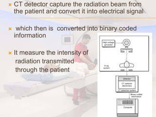
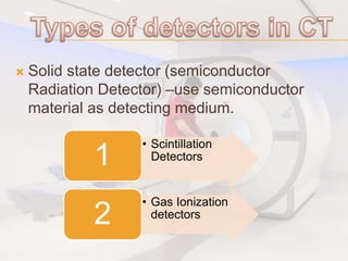
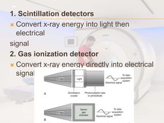
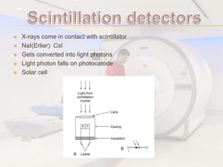
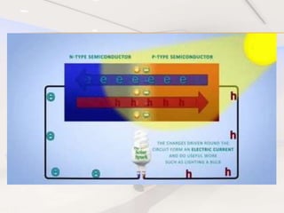
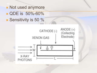
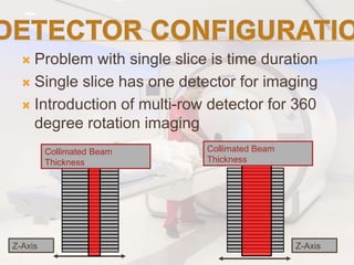
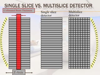
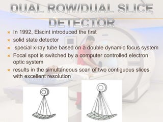
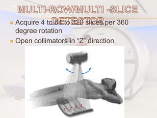
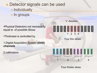
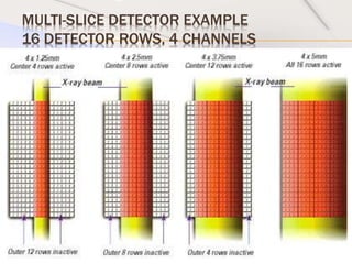
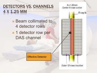
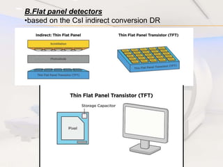
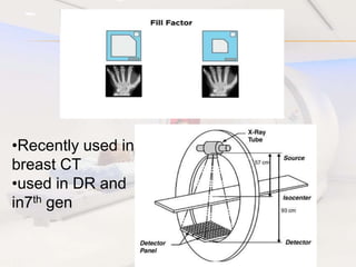
This document discusses different types of CT detectors. It describes how CT detectors work by capturing x-ray radiation from patients and converting it into electrical signals and digital information. It then summarizes the key characteristics of different detector technologies, including high efficiency, fast response time, high dynamic range, and lack of afterglow. Solid state and scintillation detectors are described as the main types that either use semiconductor materials or convert x-rays to light for detection. The advantages of multi-slice detectors over single-slice are also highlighted.
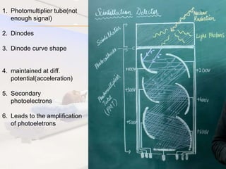


![Hypothalamus short ppt by Dr. Neha [PT].pptx](https://cdn.slidesharecdn.com/ss_thumbnails/hypothalamusbydr-260124145759-b9f94a93-thumbnail.jpg?width=640&height=640&fit=bounds)


