Download as PDF, PPTX

![Pump Power
Pumps convert mechanical power into hydraulic
power. From the definition of power P=Fv
In its motion,
the piston exerts a force [F] on the fluid that is equal to
the pressure differential in the piston Δp times
the area A of the piston, and
the velocity v is equal to
the flow rate q divided by the area A, that is
For PH in hp, p in psi, and q in gpm we have:
Spring14 H. AlamiNia Drilling Engineering 1 Course (2nd Ed.) 9](https://image.slidesharecdn.com/alezckx3q0iudsxbttqx-140509203624-phpapp02/85/Q922-de1-l05-v1-9-320.jpg)
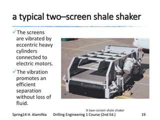
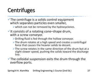
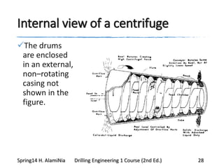

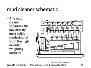
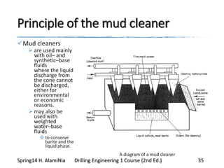
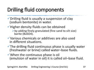
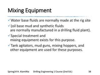
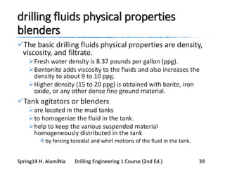


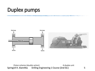
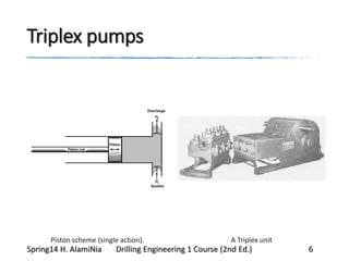
The document discusses drilling fluid systems used in oil and gas drilling. It describes the main components, including mud pumps that circulate drilling fluid, solids control equipment to remove cuttings from the fluid, and treatment/mixing equipment. It focuses on duplex and triplex mud pumps, explaining their piston configurations and how to calculate their flow rates and power requirements. Solids control equipment like shale shakers, hydrocyclones, centrifuges, and mud cleaners are also outlined.


