Download as PDF, PPTX
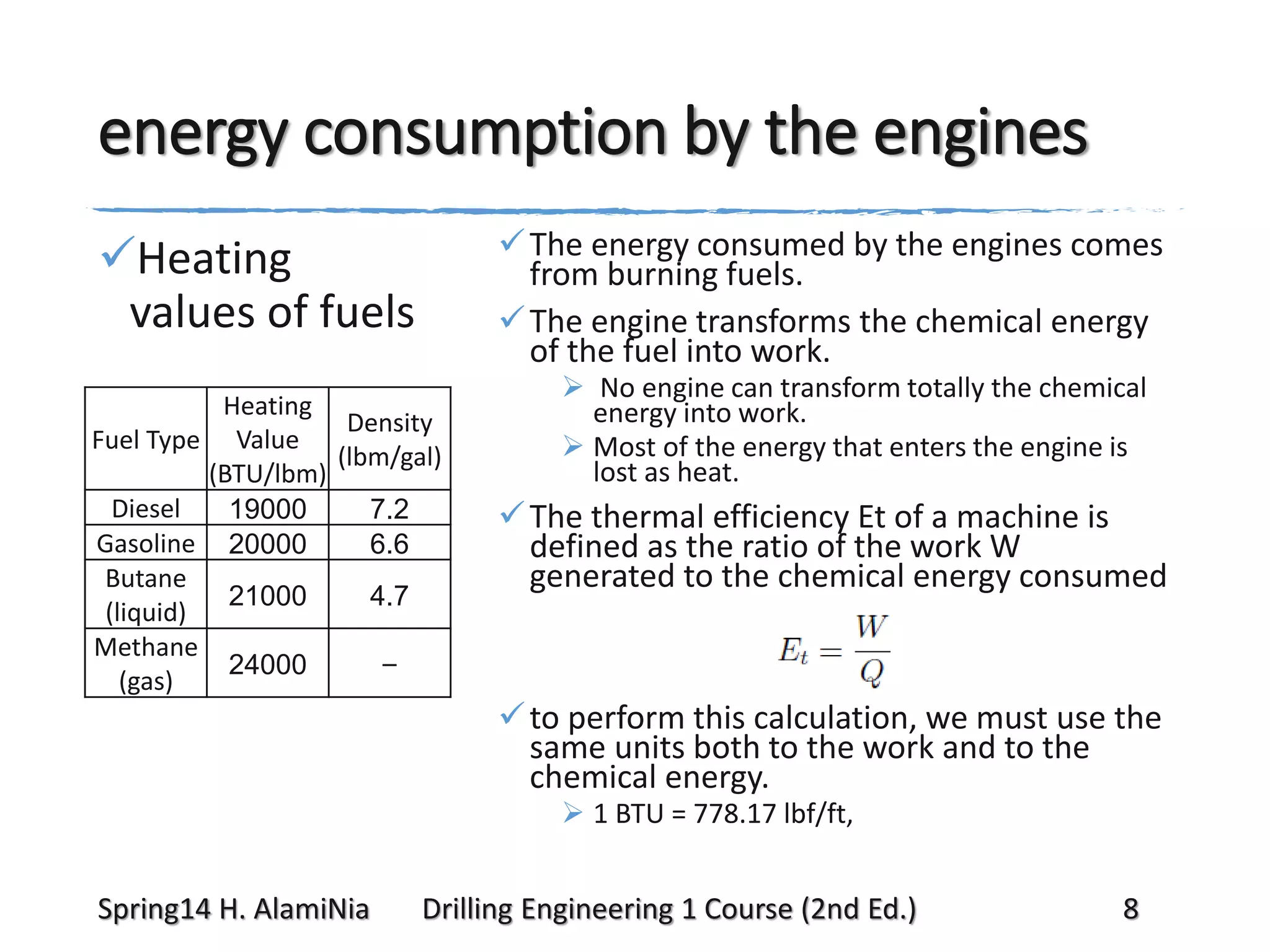

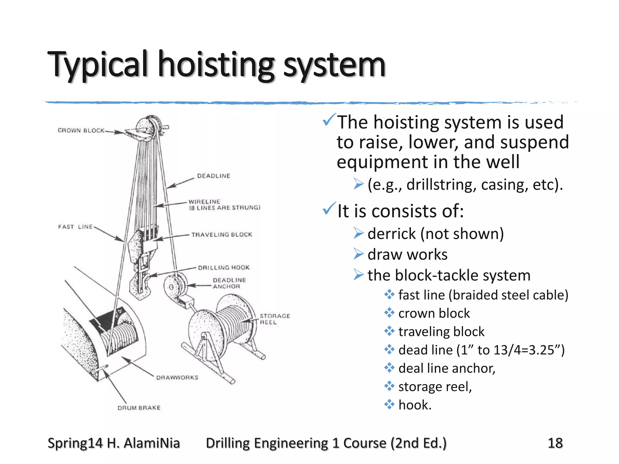

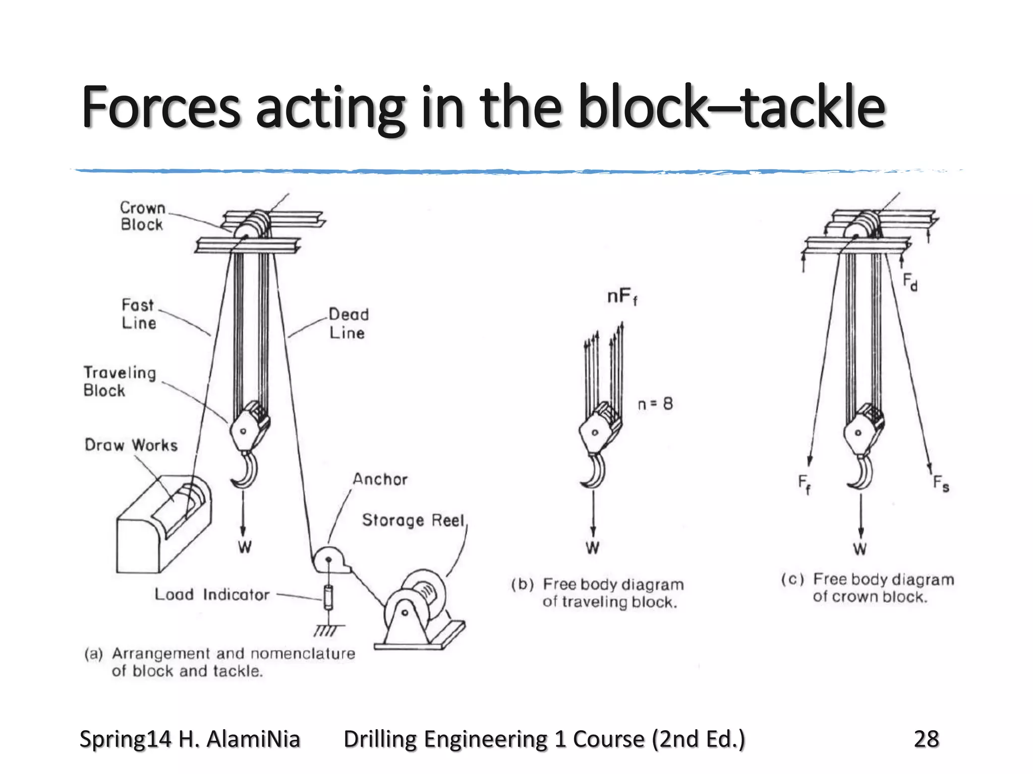

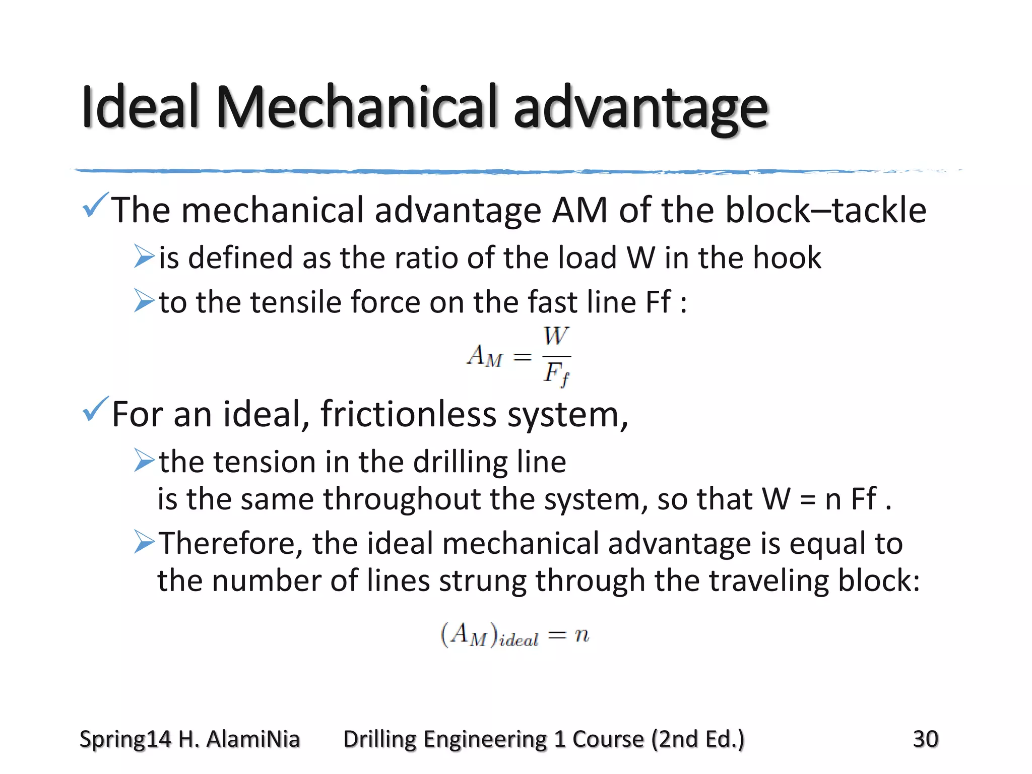
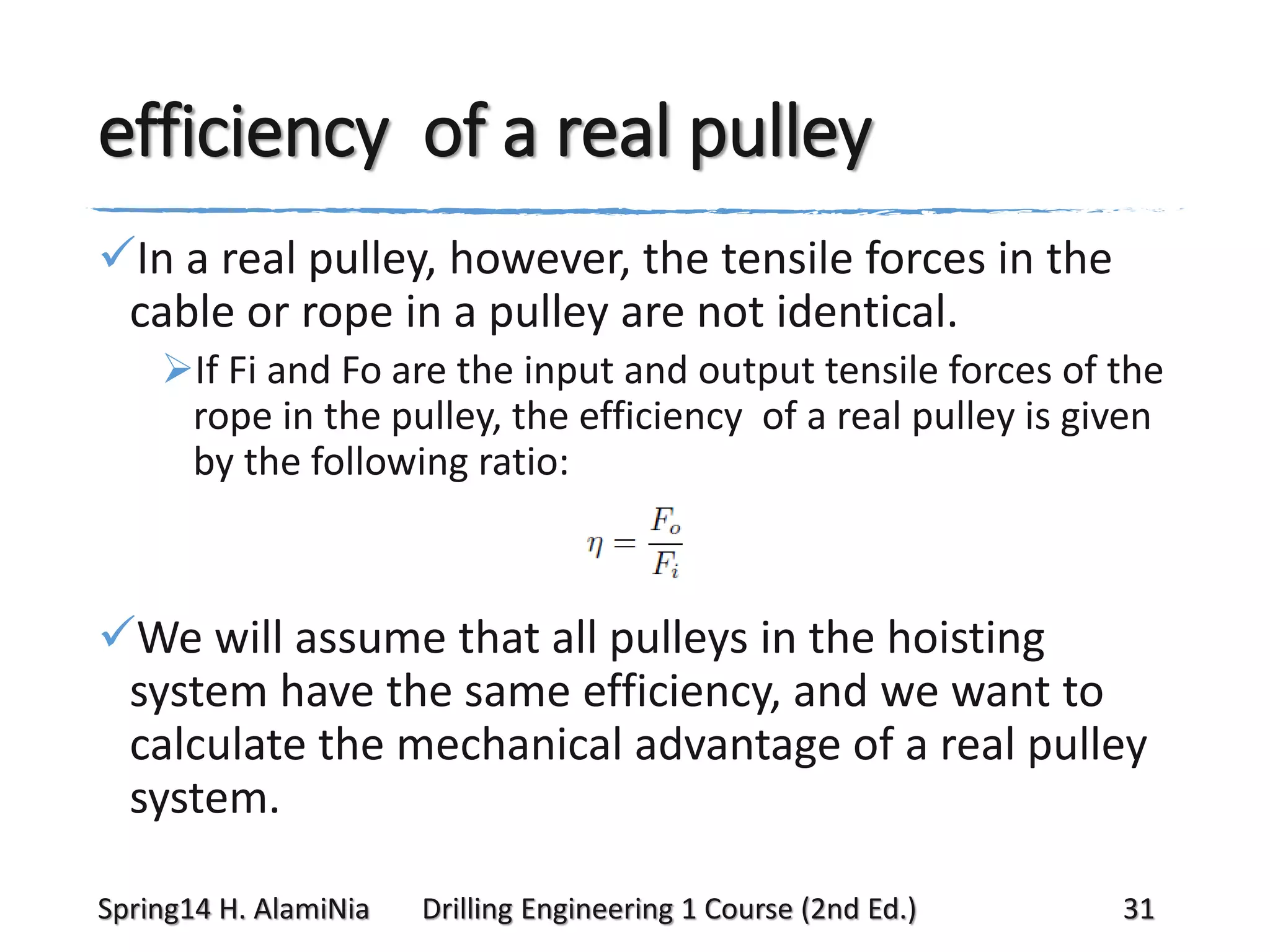
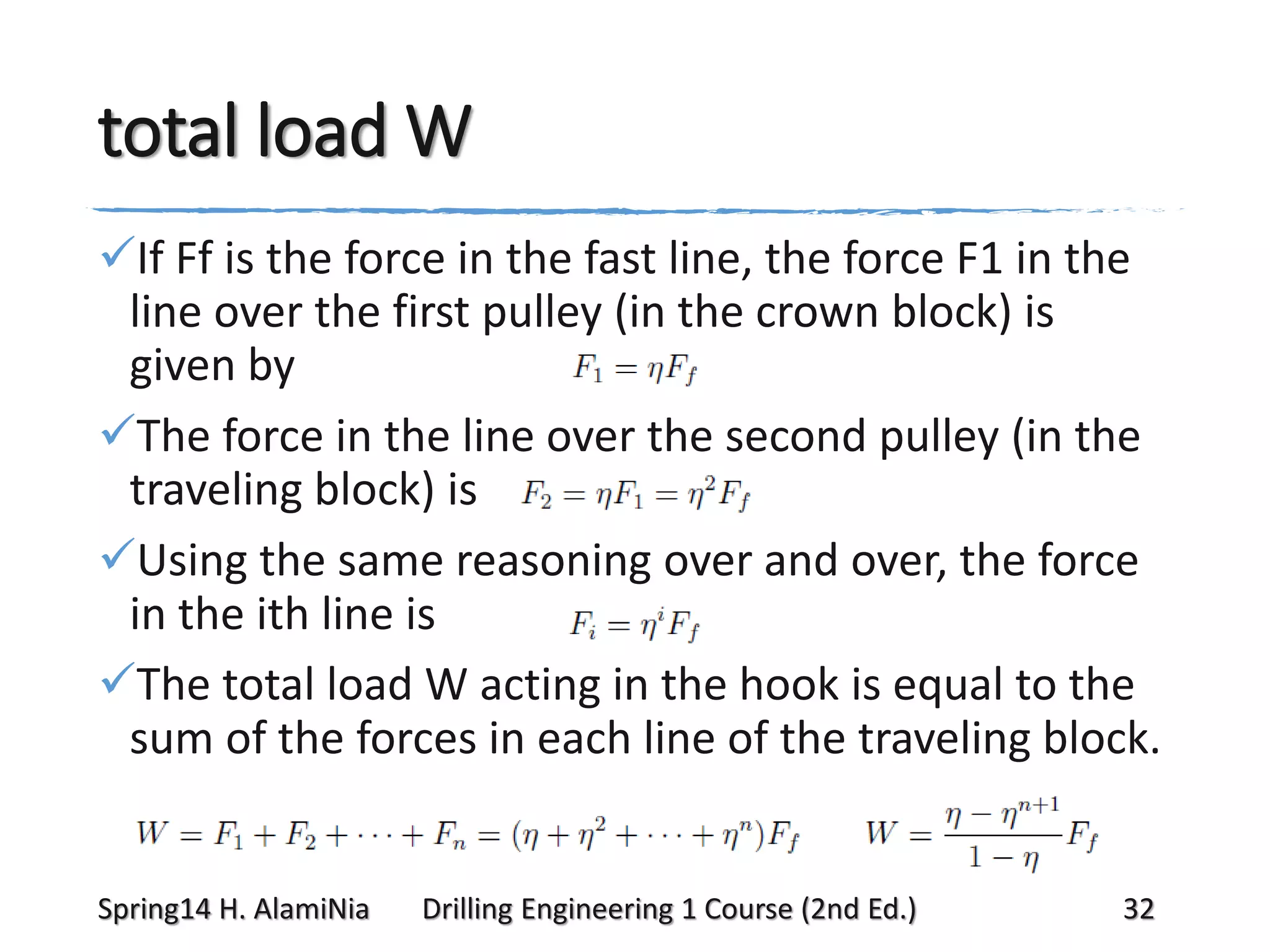
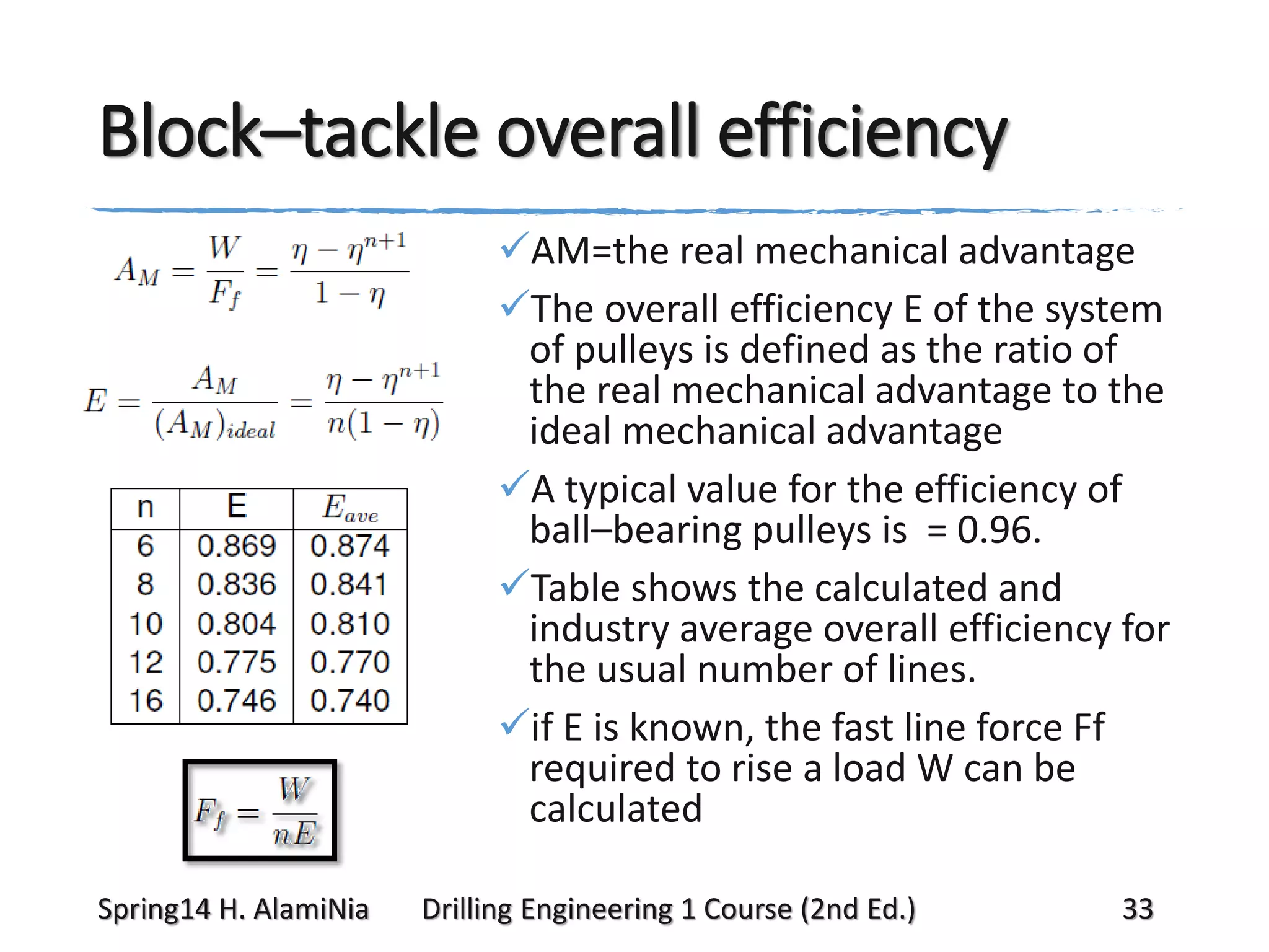


This document provides an overview of the power and hoisting systems used on rotary drilling rigs. It discusses the typical components of a rig's power system, including diesel engines that provide mechanical or electric power. It also details the components that make up the hoisting system, including the derrick, drawworks, block and tackle pulley system, and their functions in raising and lowering equipment in the well. The block and tackle provides mechanical advantage to reduce the load on the drawworks. Formulas are provided to calculate the fast line force required to lift a weight and the load distribution throughout the rig.