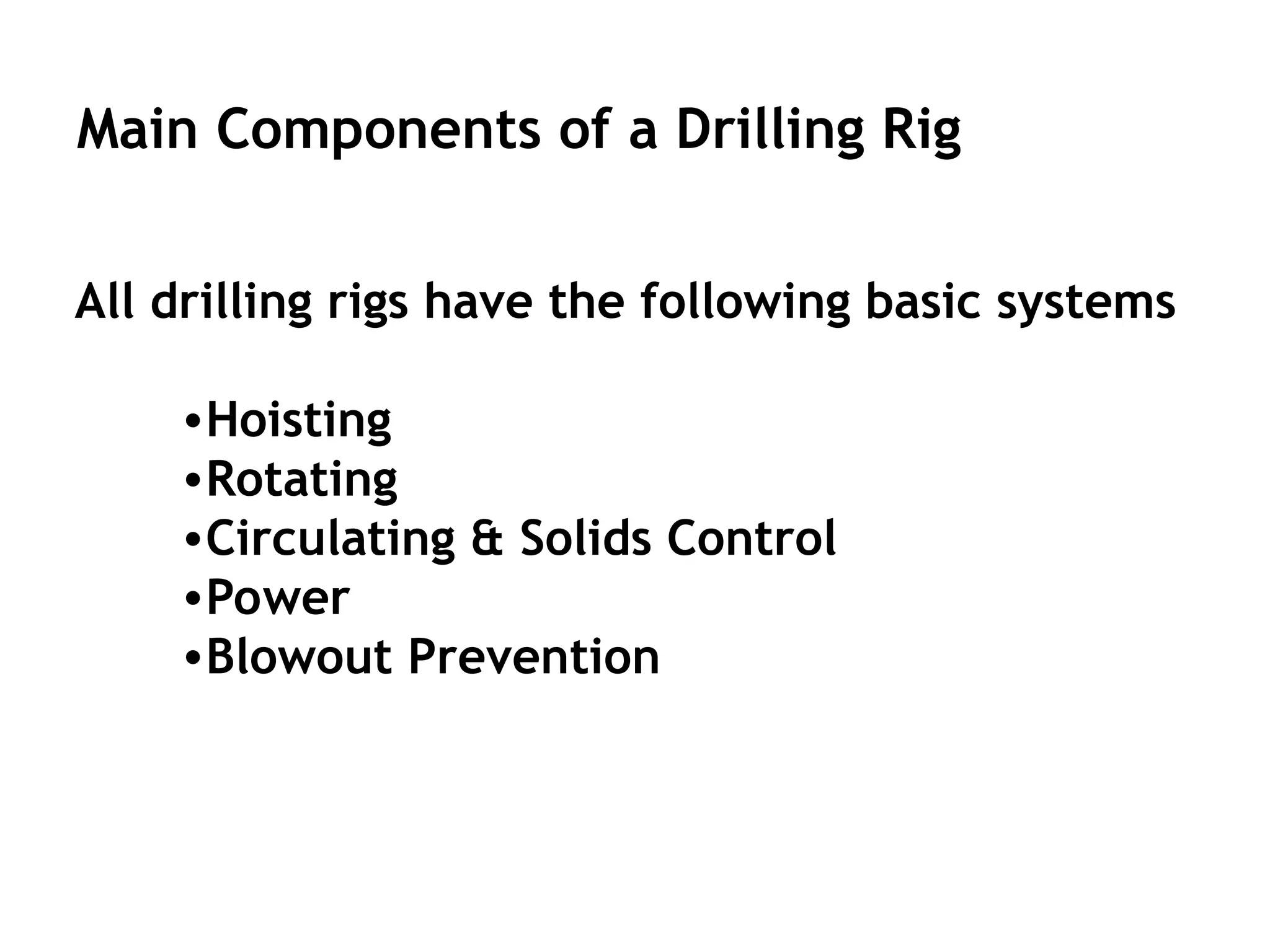
Main Components ofa Drilling Rig
All drilling rigs have the following basic systems
•Hoisting
•Rotating
•Circulating & Solids Control
•Power
•Blowout Prevention
4.
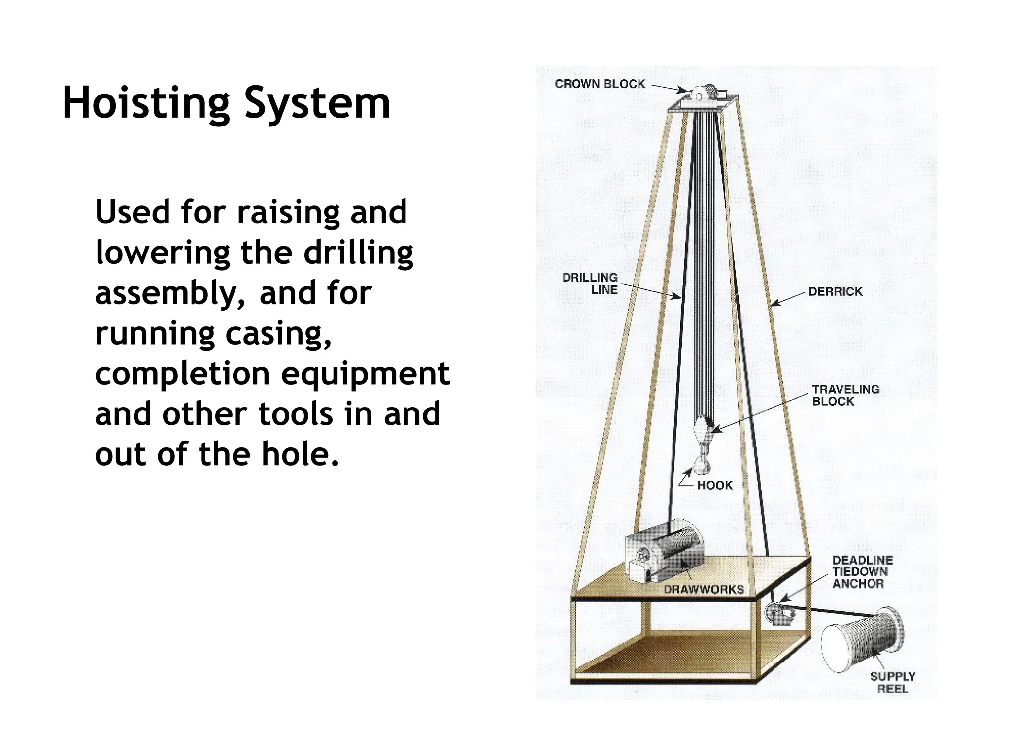
Hoisting System
Used forraising and
lowering the drilling
assembly, and for
running casing,
completion equipment
and other tools in and
out of the hole.
5.
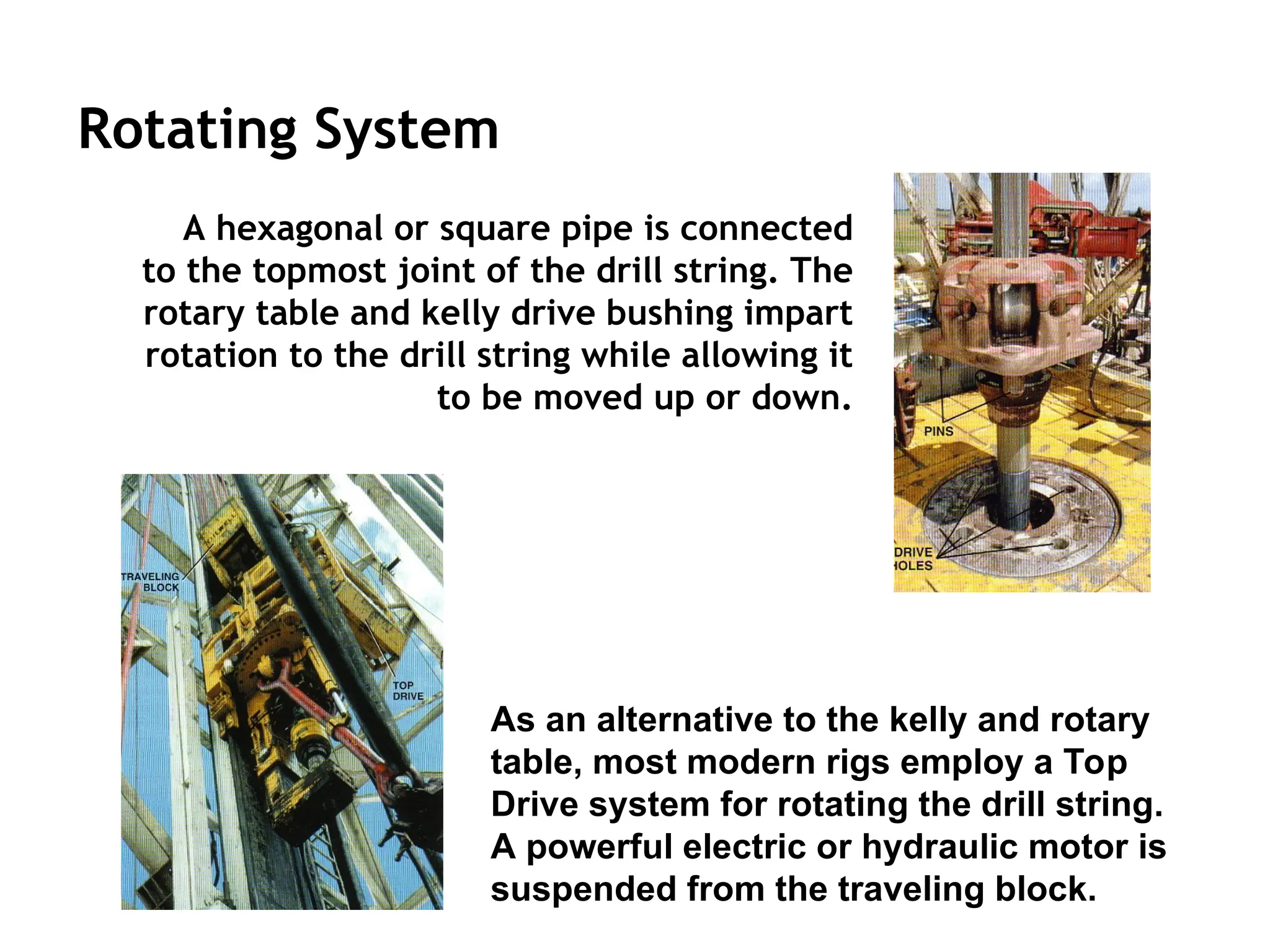
Rotating System
A hexagonalor square pipe is connected
to the topmost joint of the drill string. The
rotary table and kelly drive bushing impart
rotation to the drill string while allowing it
to be moved up or down.
As an alternative to the kelly and rotary
table, most modern rigs employ a Top
Drive system for rotating the drill string.
A powerful electric or hydraulic motor is
suspended from the traveling block.
6.
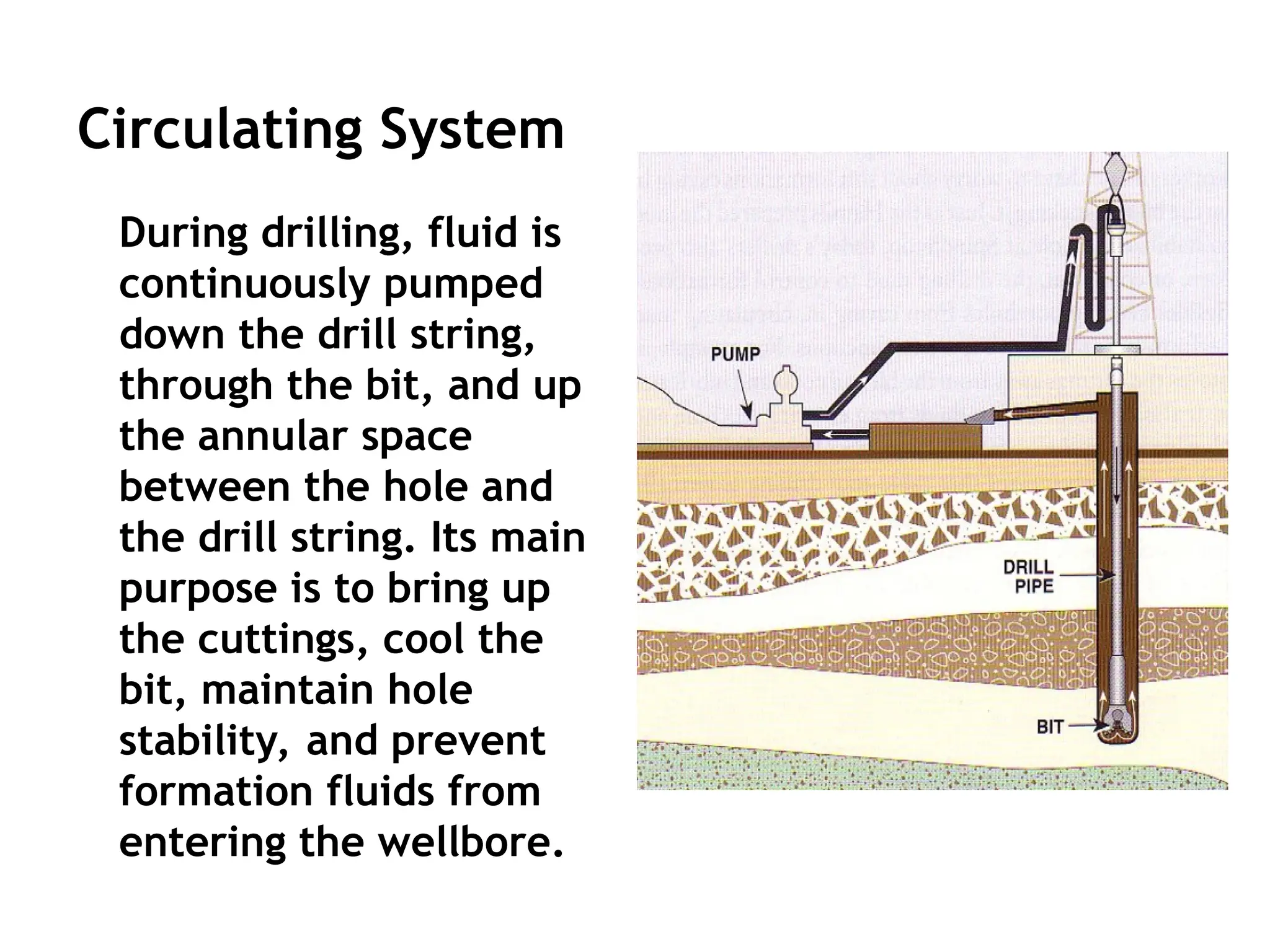
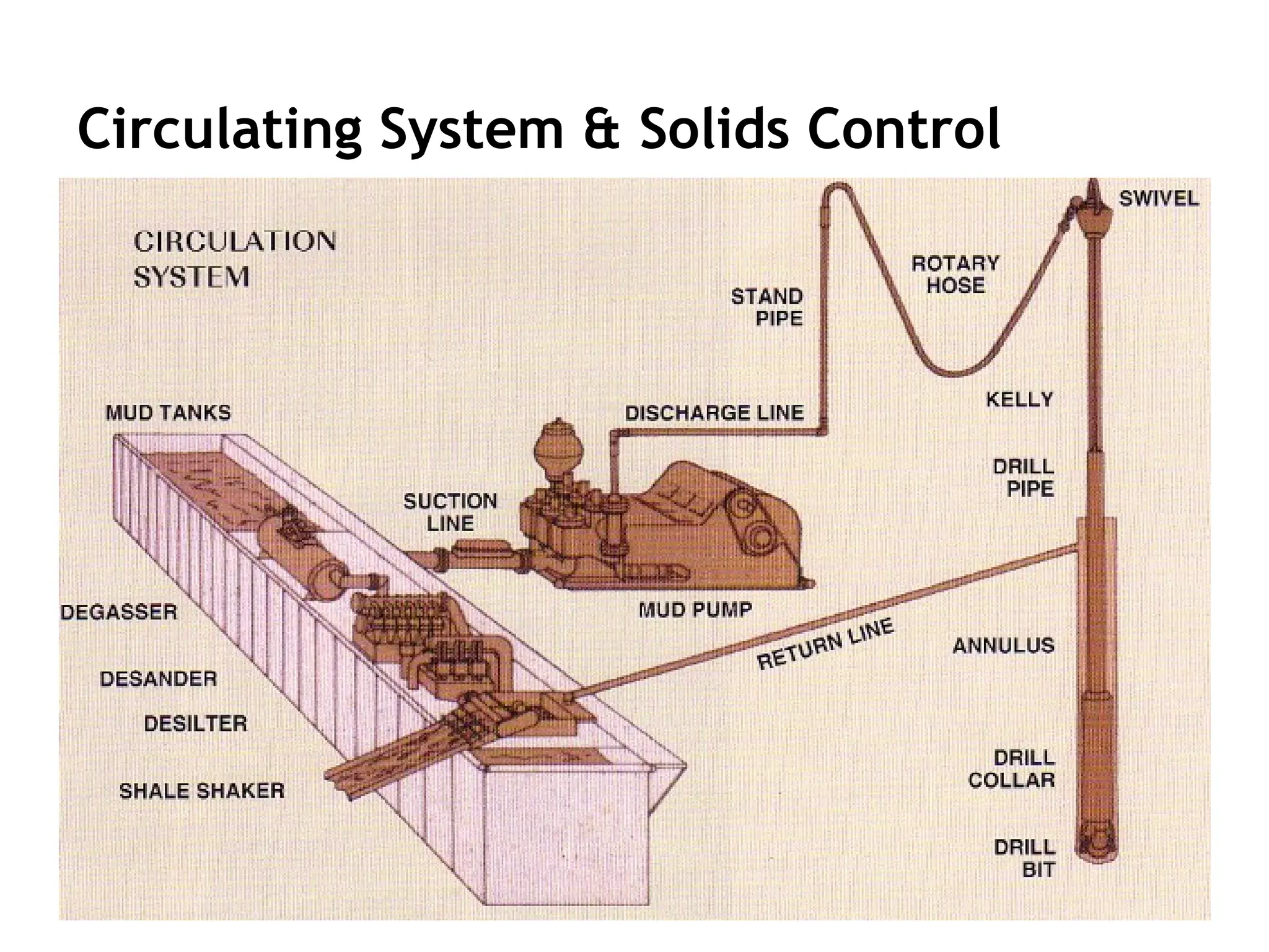
Circulating System
During drilling,fluid is
continuously pumped
down the drill string,
through the bit, and up
the annular space
between the hole and
the drill string. Its main
purpose is to bring up
the cuttings, cool the
bit, maintain hole
stability, and prevent
formation fluids from
entering the wellbore.
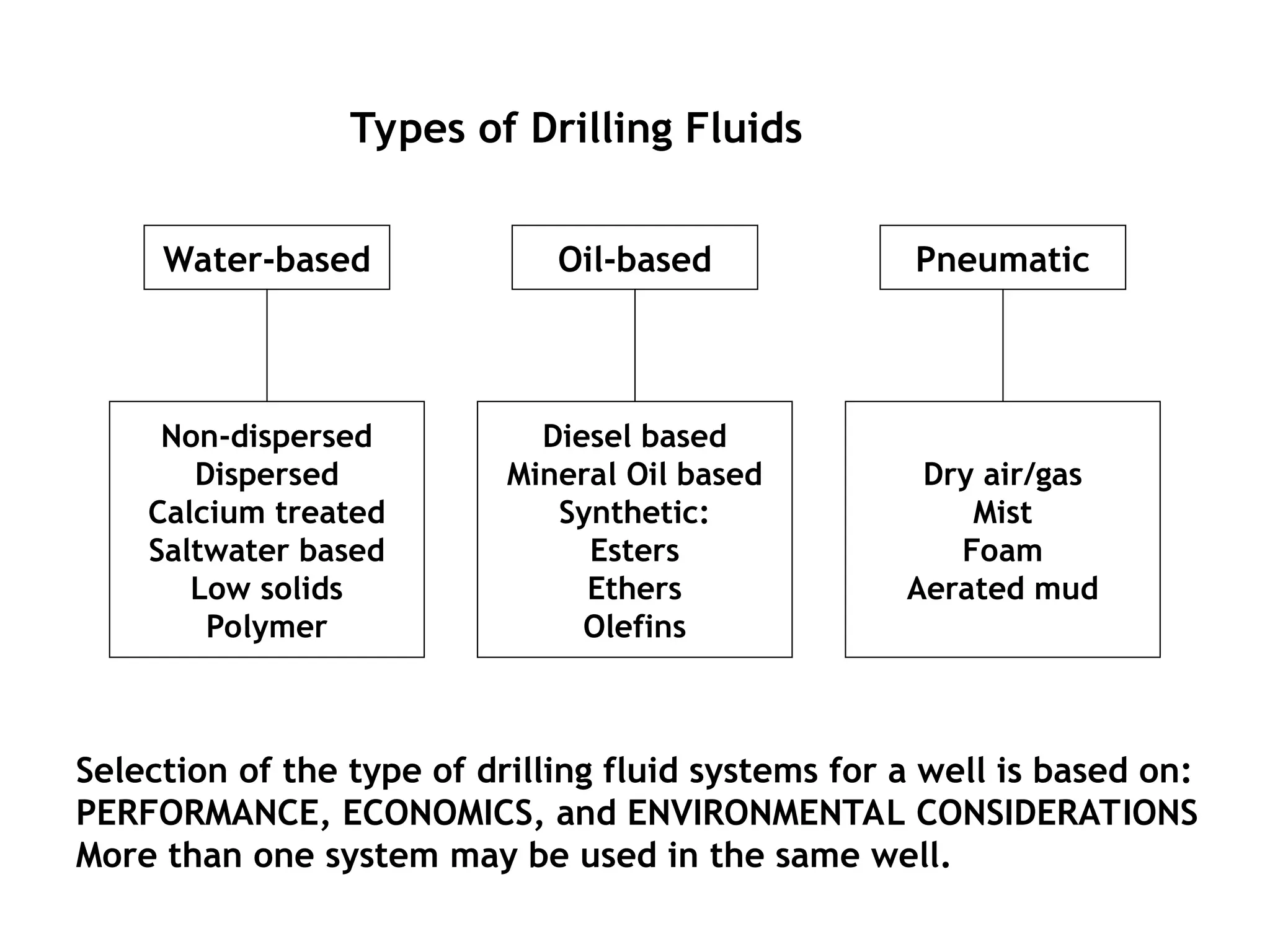
Types of DrillingFluids
Non-dispersed
Dispersed
Calcium treated
Saltwater based
Low solids
Polymer
Water-based Pneumatic
Oil-based
Diesel based
Mineral Oil based
Synthetic:
Esters
Ethers
Olefins
Dry air/gas
Mist
Foam
Aerated mud
Selection of the type of drilling fluid systems for a well is based on:
PERFORMANCE, ECONOMICS, and ENVIRONMENTAL CONSIDERATIONS
More than one system may be used in the same well.
9.
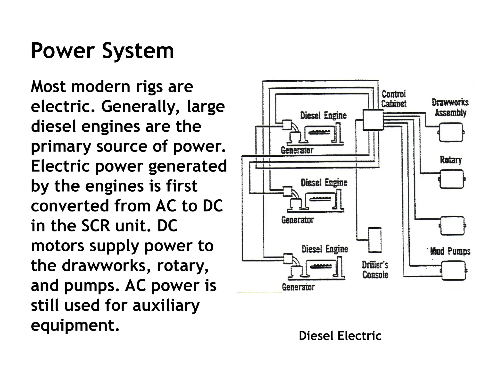
Diesel Electric
Power System
Mostmodern rigs are
electric. Generally, large
diesel engines are the
primary source of power.
Electric power generated
by the engines is first
converted from AC to DC
in the SCR unit. DC
motors supply power to
the drawworks, rotary,
and pumps. AC power is
still used for auxiliary
equipment.
10.
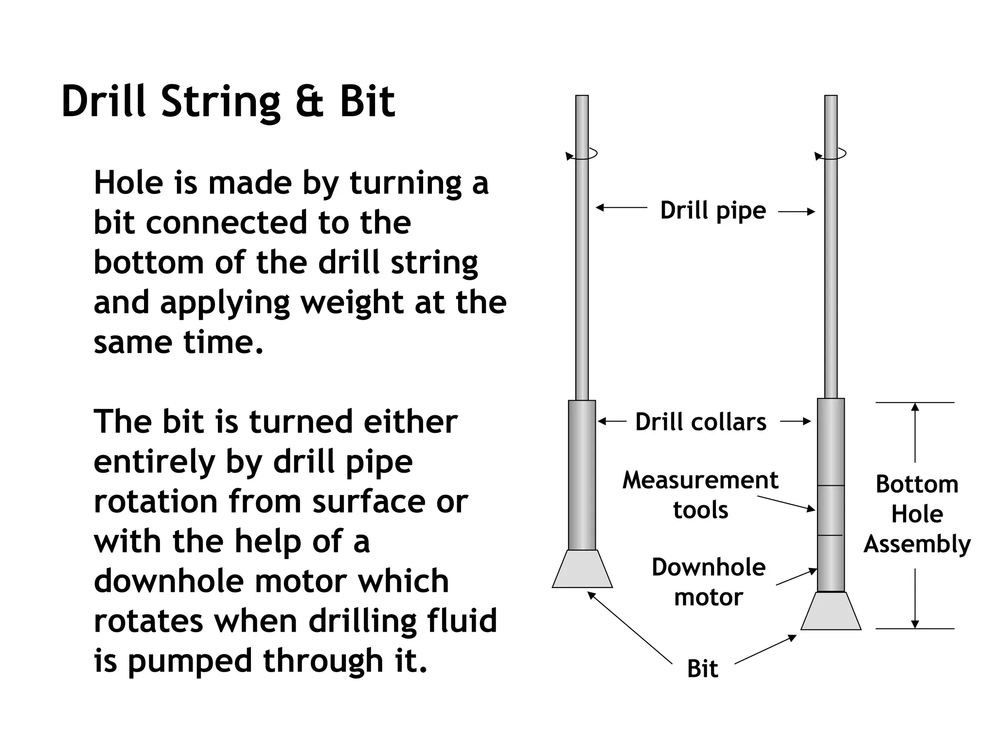
Drill String &Bit
Hole is made by turning a
bit connected to the
bottom of the drill string
and applying weight at the
same time.
The bit is turned either
entirely by drill pipe
rotation from surface or
with the help of a
downhole motor which
rotates when drilling fluid
is pumped through it.
Drill pipe
Drill collars
Measurement
tools
Downhole
motor
Bottom
Hole
Assembly
Bit
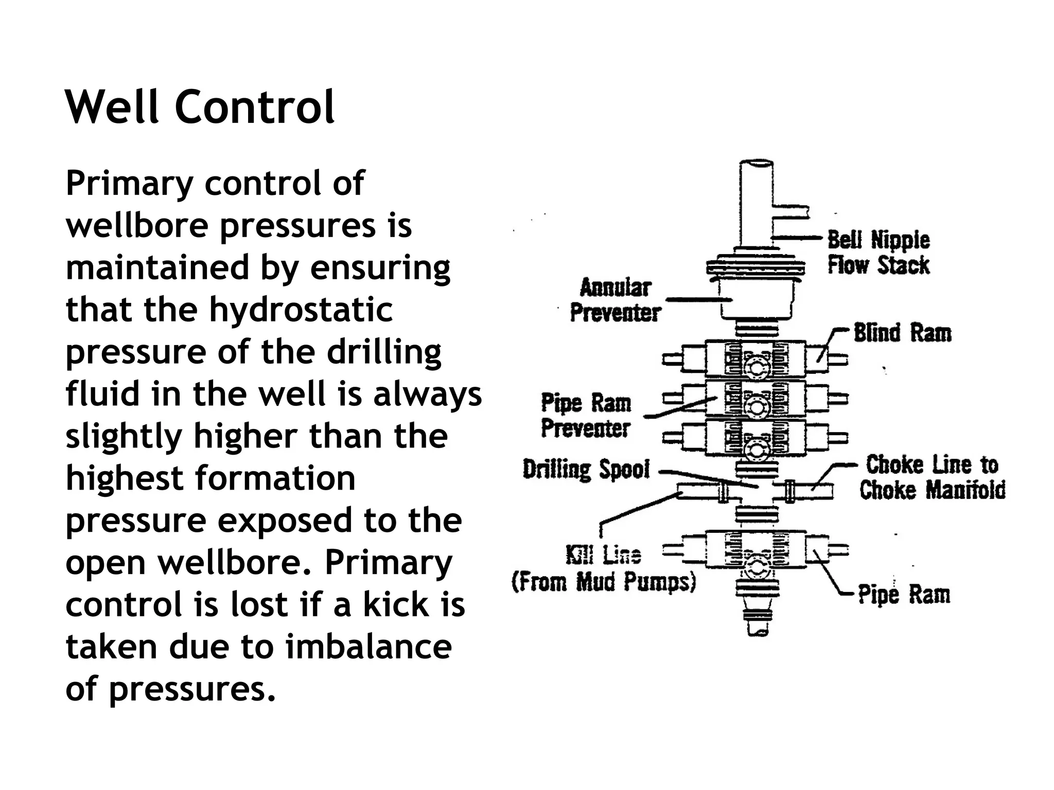
Well Control
Primary controlof
wellbore pressures is
maintained by ensuring
that the hydrostatic
pressure of the drilling
fluid in the well is always
slightly higher than the
highest formation
pressure exposed to the
open wellbore. Primary
control is lost if a kick is
taken due to imbalance
of pressures.
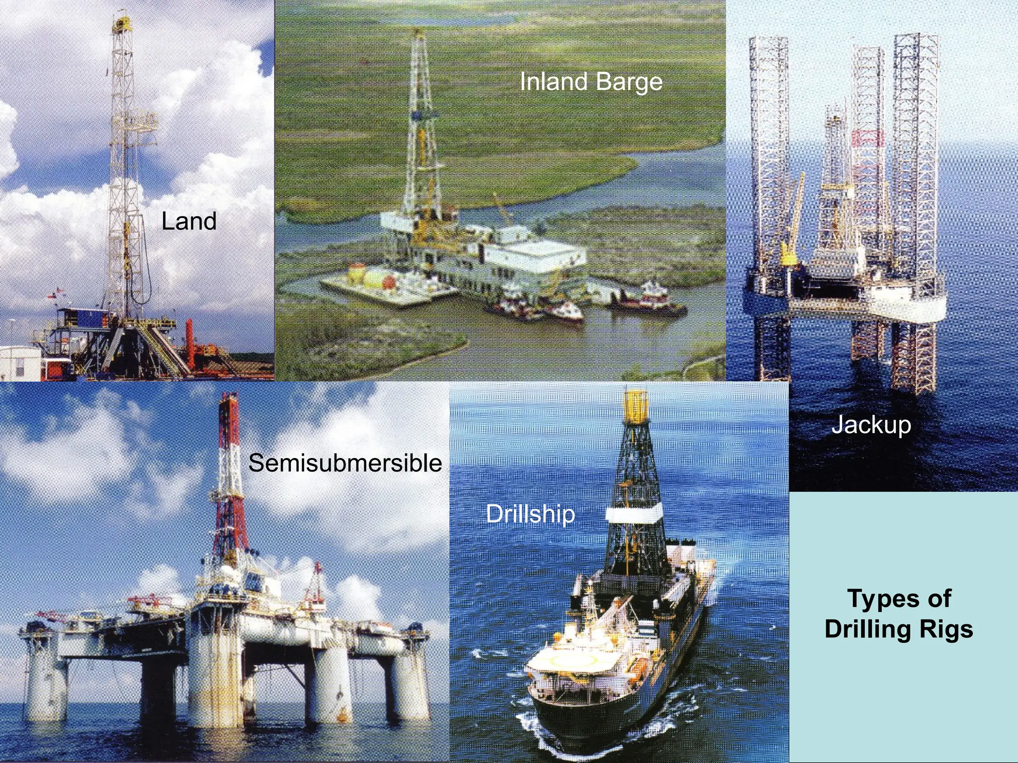
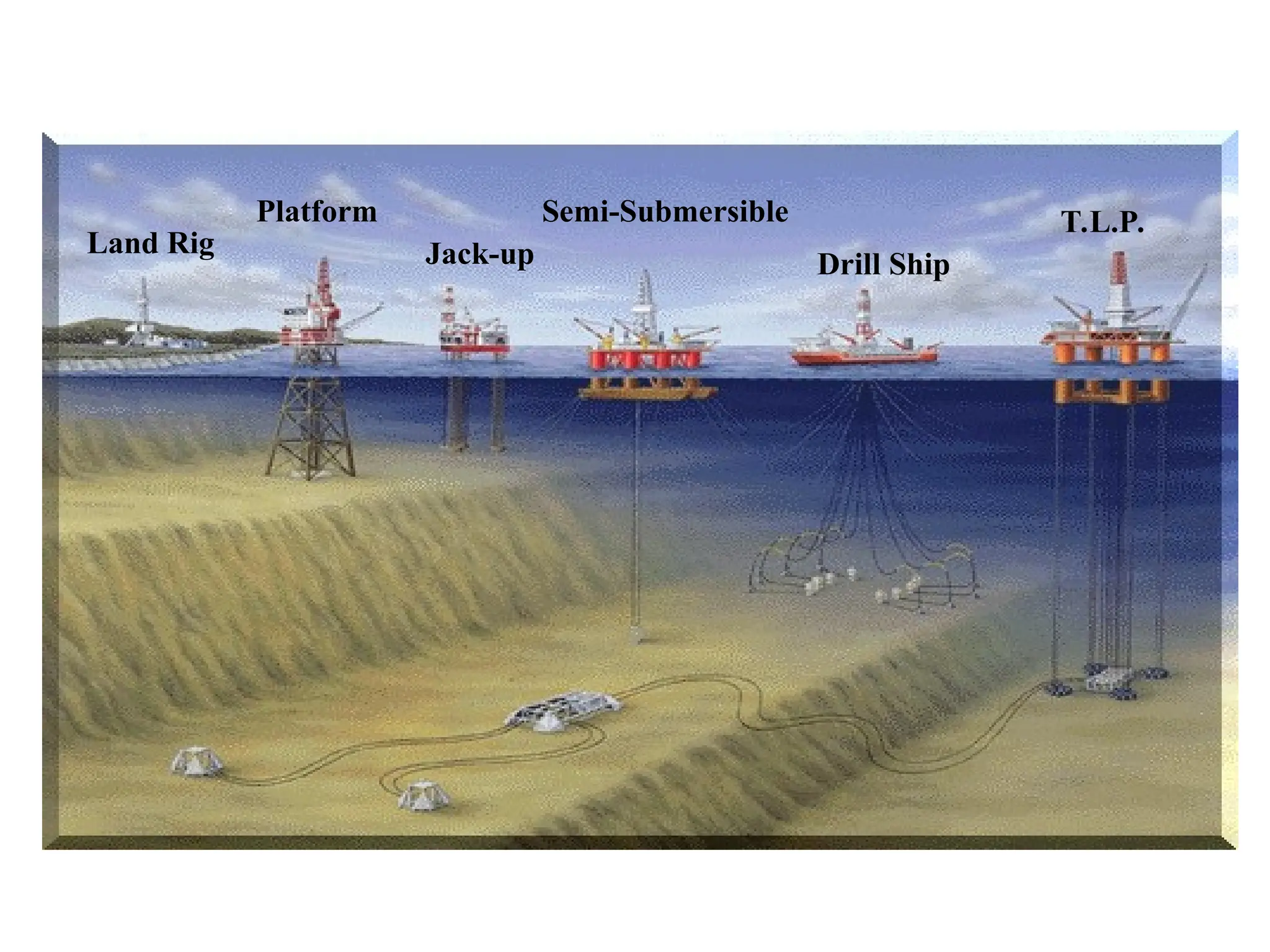
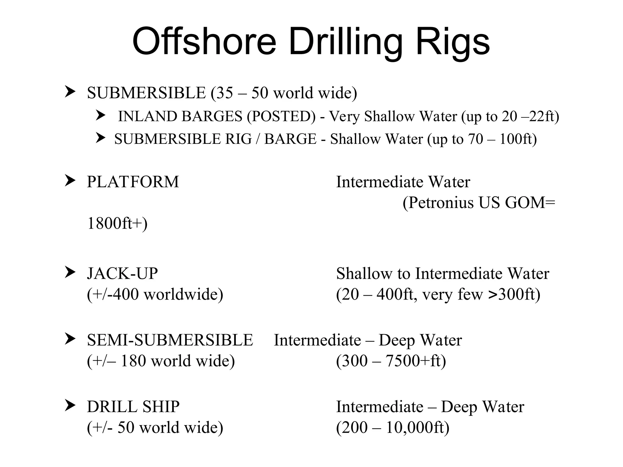
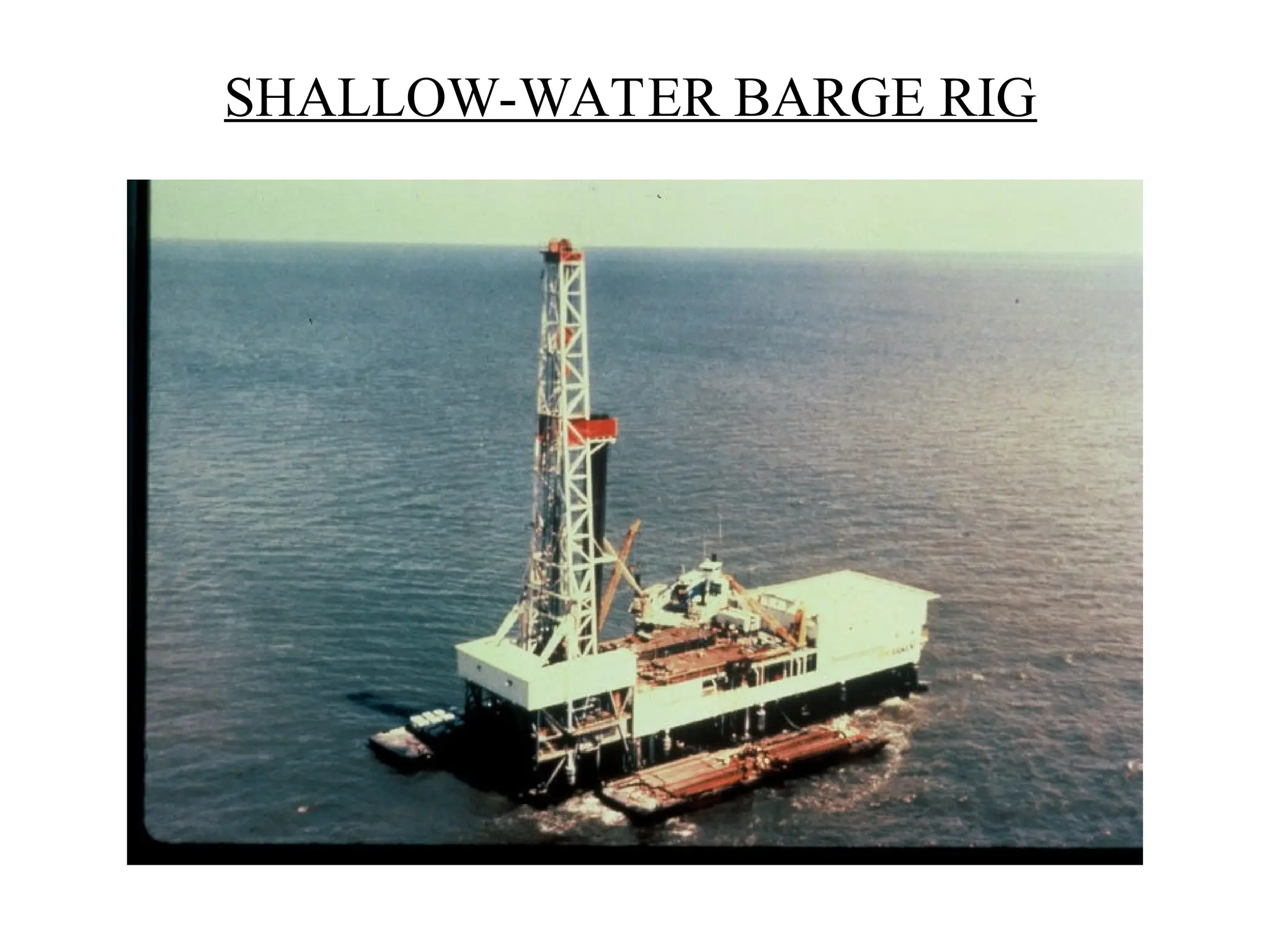
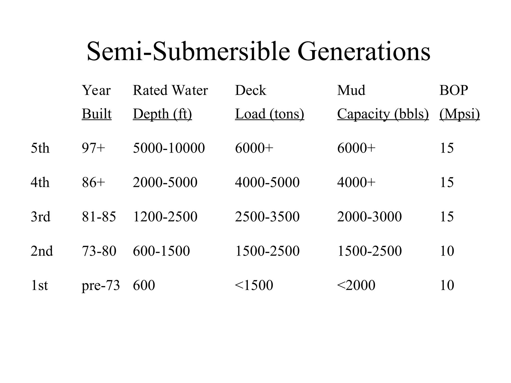
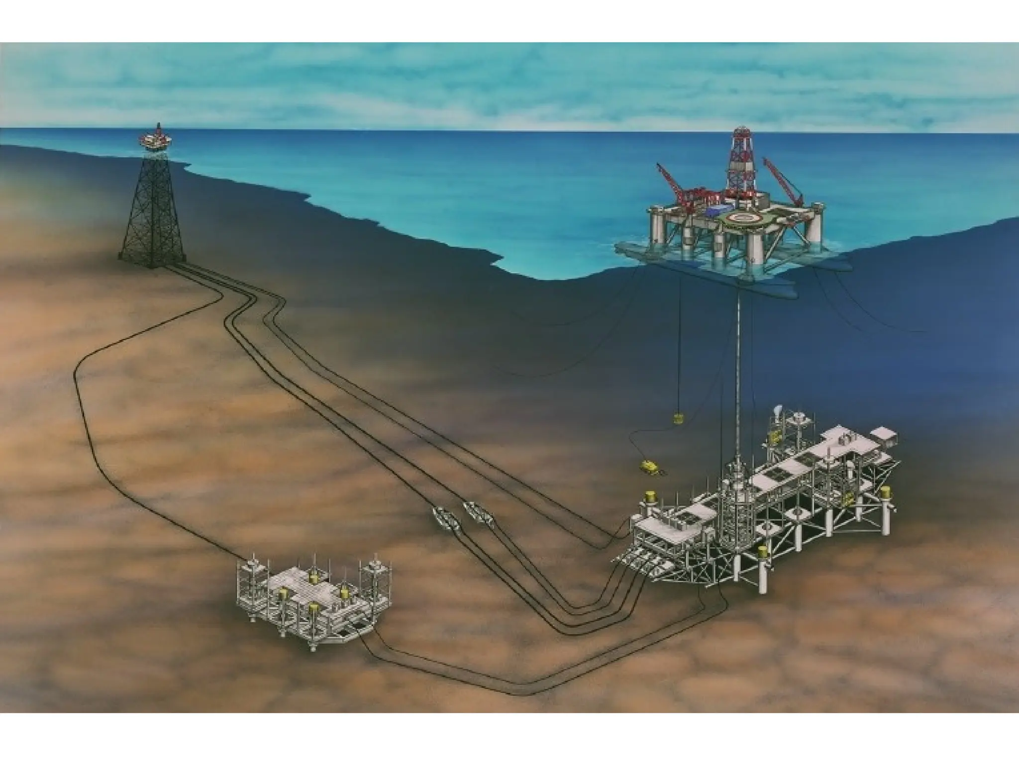
Offshore Drilling Rigs
SUBMERSIBLE (35 – 50 world wide)
INLAND BARGES (POSTED) - Very Shallow Water (up to 20 –22ft)
SUBMERSIBLE RIG / BARGE - Shallow Water (up to 70 – 100ft)
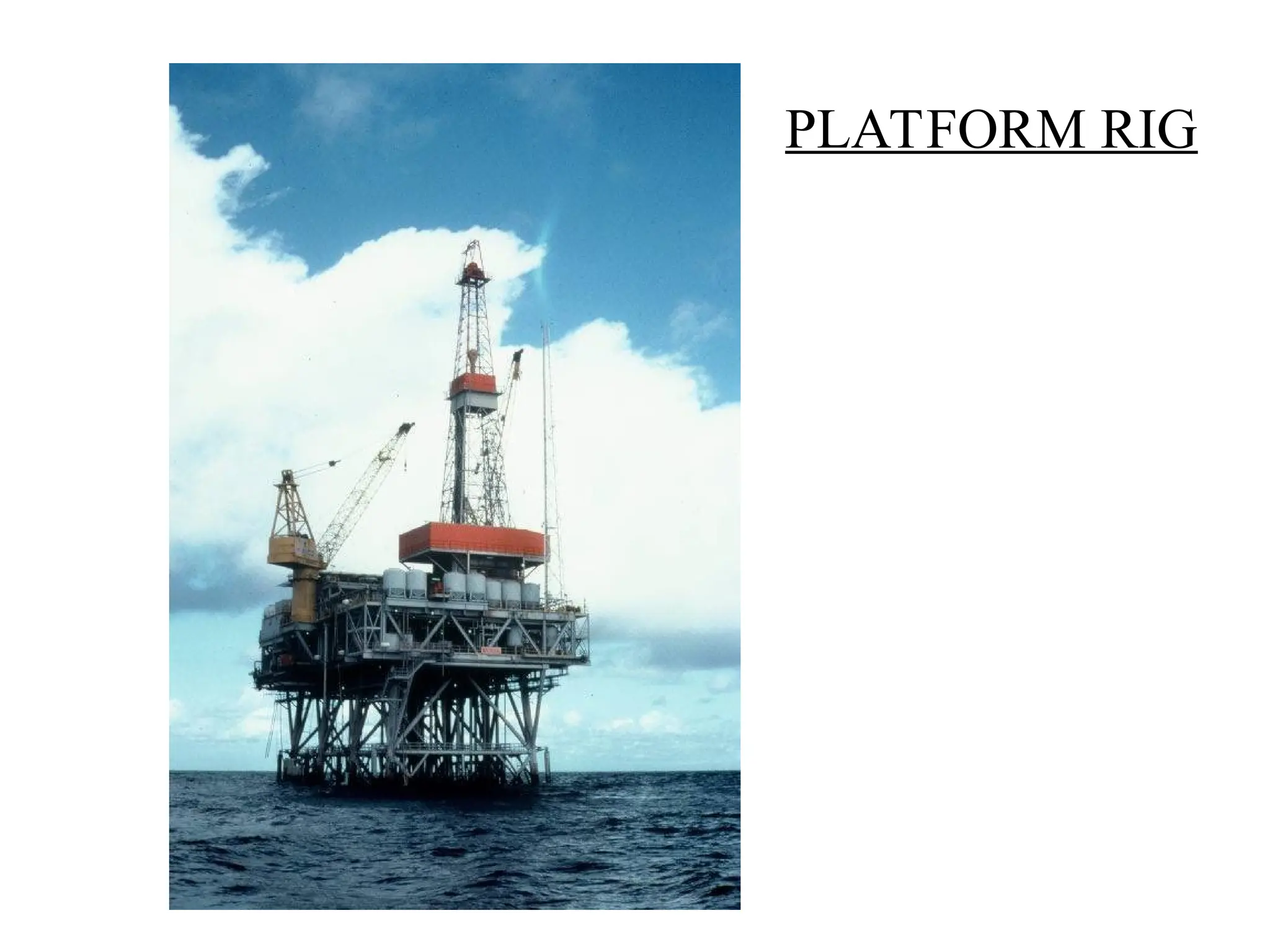
PLATFORM Intermediate Water
(Petronius US GOM=
1800ft+)
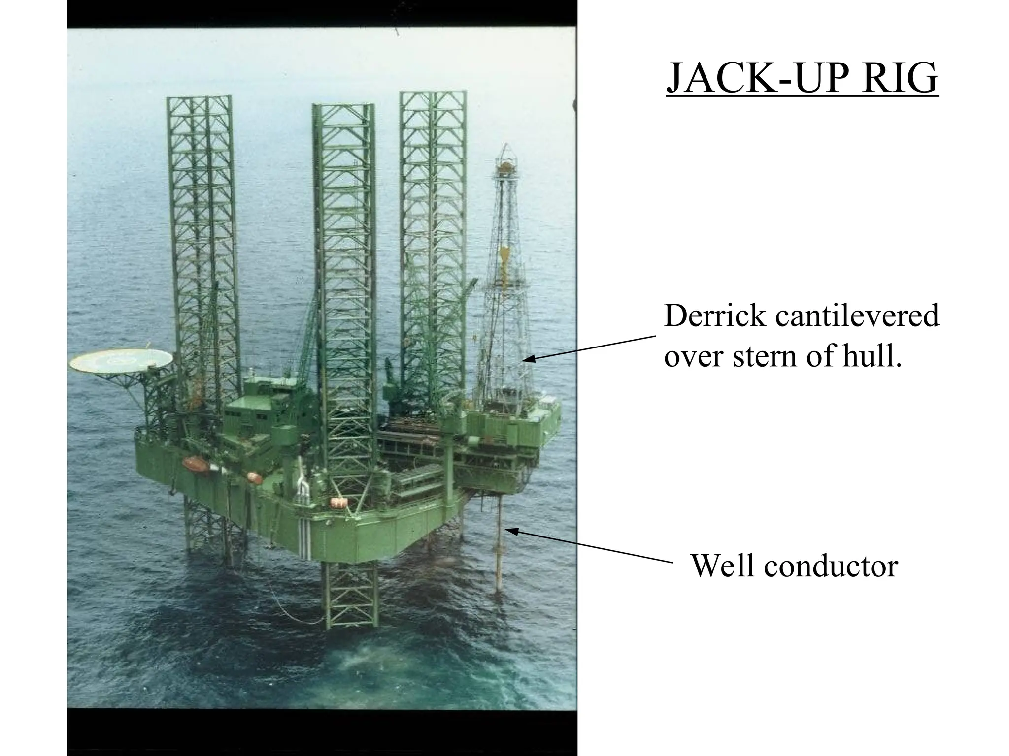
JACK-UP Shallow to Intermediate Water
(+/-400 worldwide) (20 – 400ft, very few 300ft)
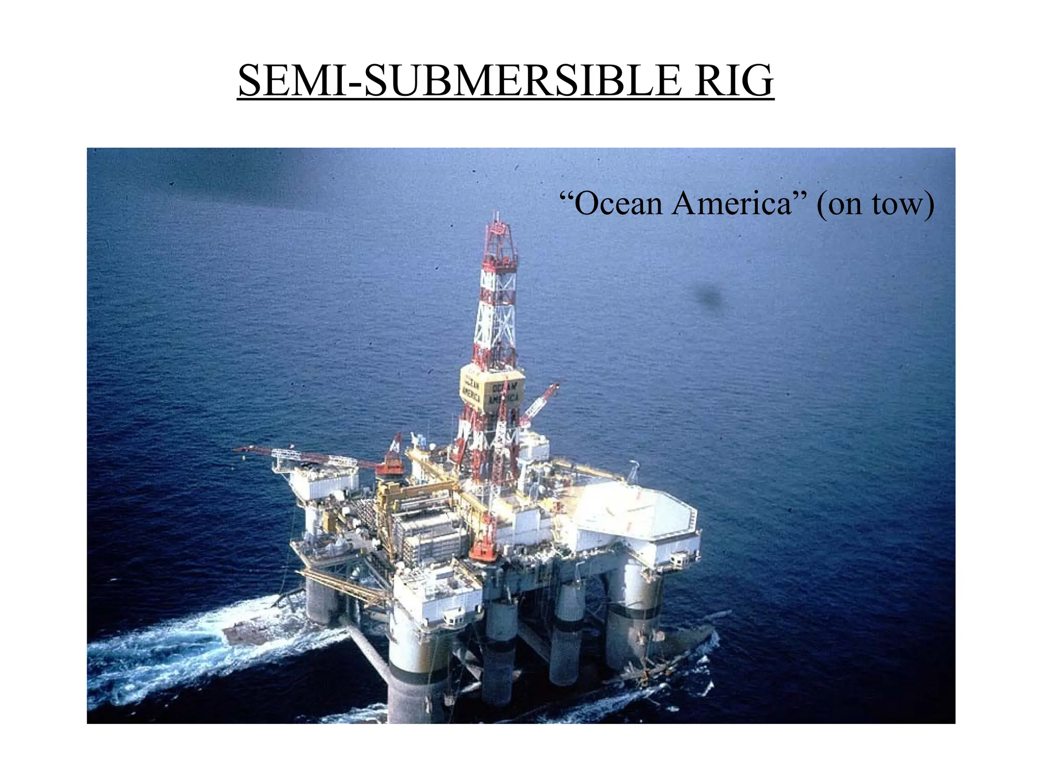
SEMI-SUBMERSIBLE Intermediate – Deep Water
(+/– 180 world wide) (300 – 7500+ft)
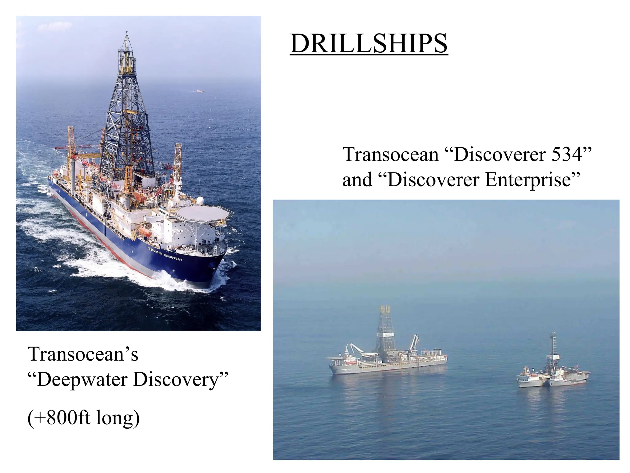
DRILL SHIP Intermediate – Deep Water
(+/- 50 world wide) (200 – 10,000ft)
Well Construction andWell Types
By Objective
• Exploration
•P&A or keeper
• Delineation
•Size of reservoir
• Appraisal
•Reservoir
characteristics
• Development
•Reservoir drainage
• Injection
•Pressure
maintenance
0 ft Rig Datum - RKB
Mud Wt (ppg)
D
ep
th
(feet)
PP FG
Mud Wt (ppg)
D
ep
th
(feet)
PP FG
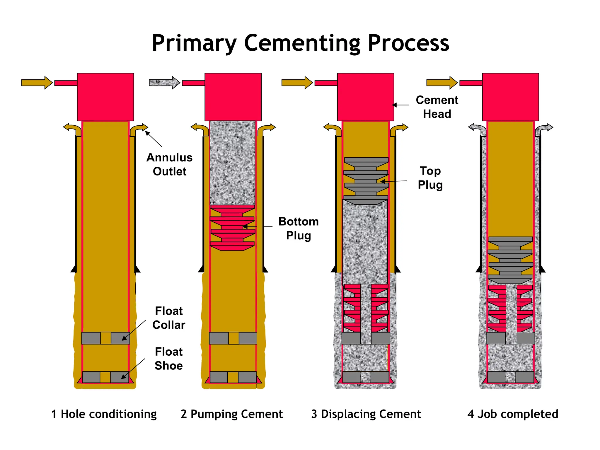
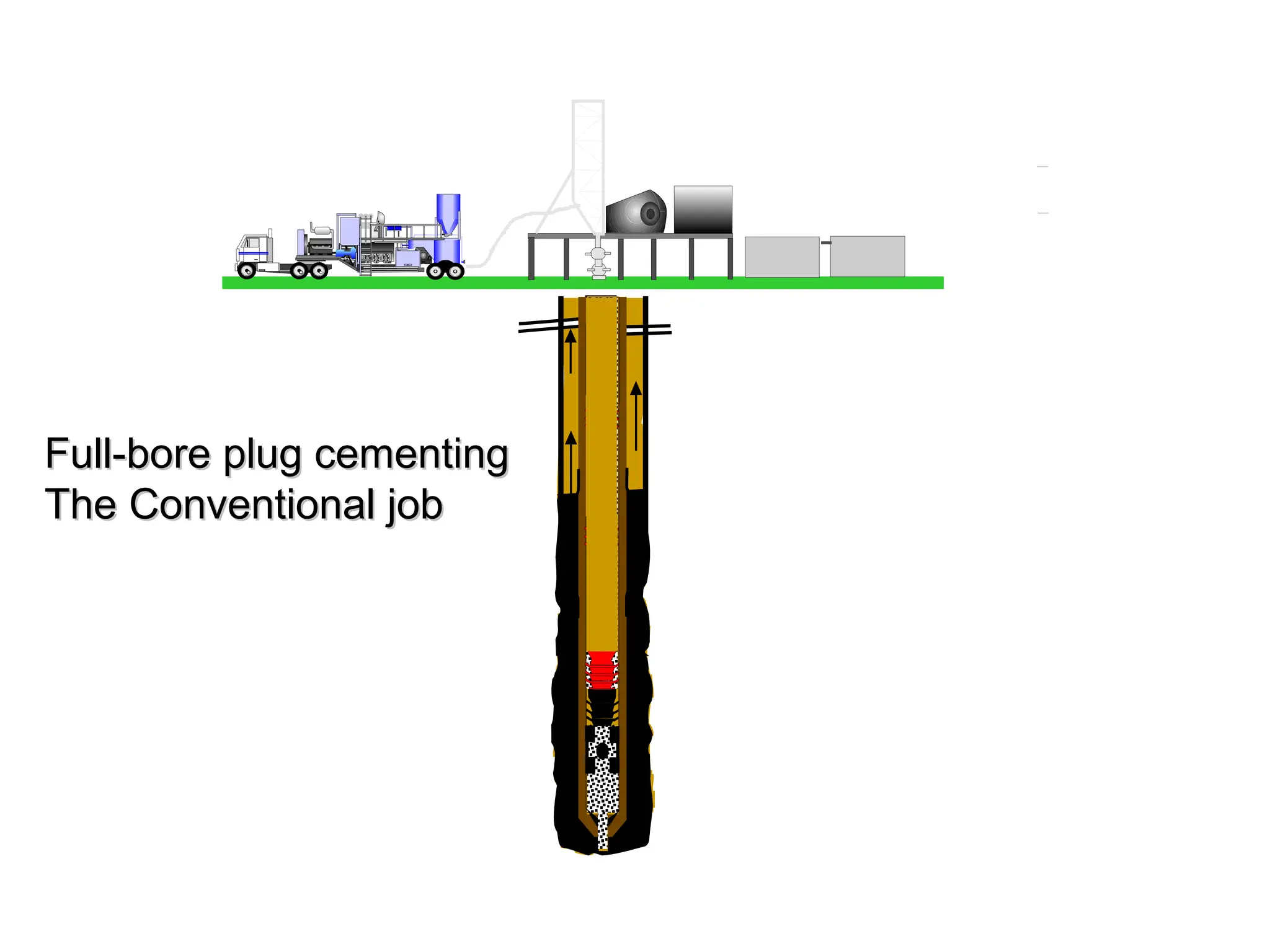
26.
Primary Cementing Process
3Displacing Cement 4 Job completed
2 Pumping Cement
Bottom
Plug
Top
Plug
Cement
Head
1 Hole conditioning
Float
Shoe
Float
Collar
Annulus
Outlet
Directional Drilling -Why?
• On Land:
– Surface constraint due to
land owner, natural
event, etc.
– Relief well in blowout
situation
– Horizontal
• Offshore:
– Save Cost on Platform
– Relief well in blowout situation
– Horizontal
– Extended Reach
– Multi-Lateral
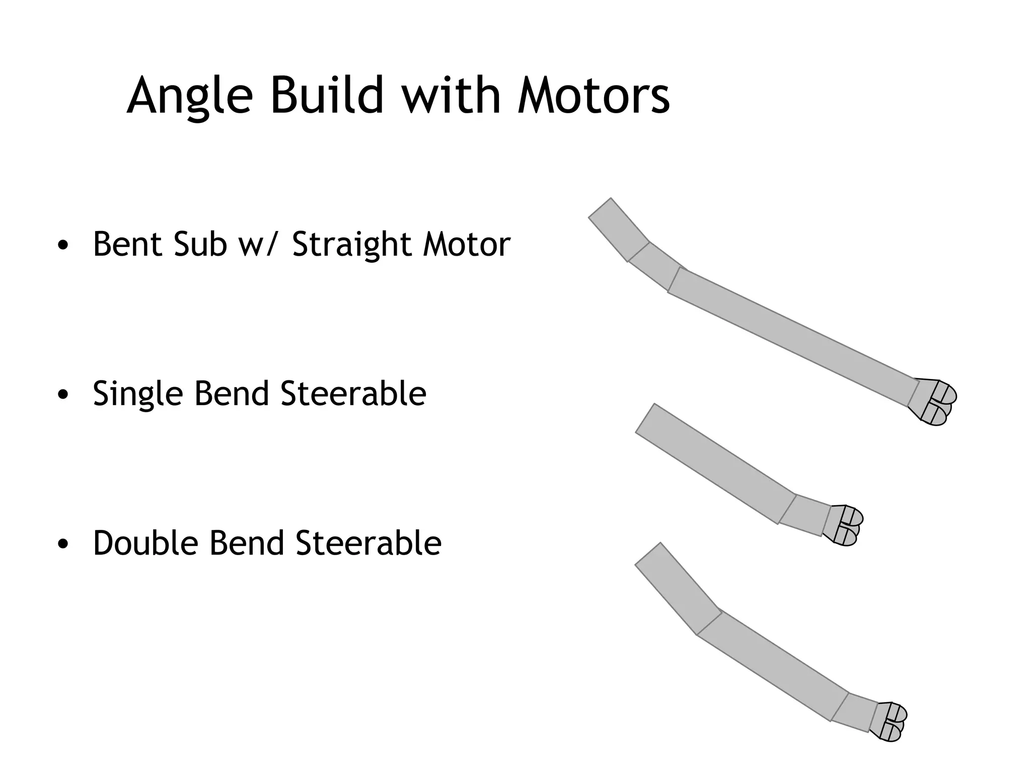
29.
Angle Build withMotors
• Bent Sub w/ Straight Motor
• Single Bend Steerable
• Double Bend Steerable
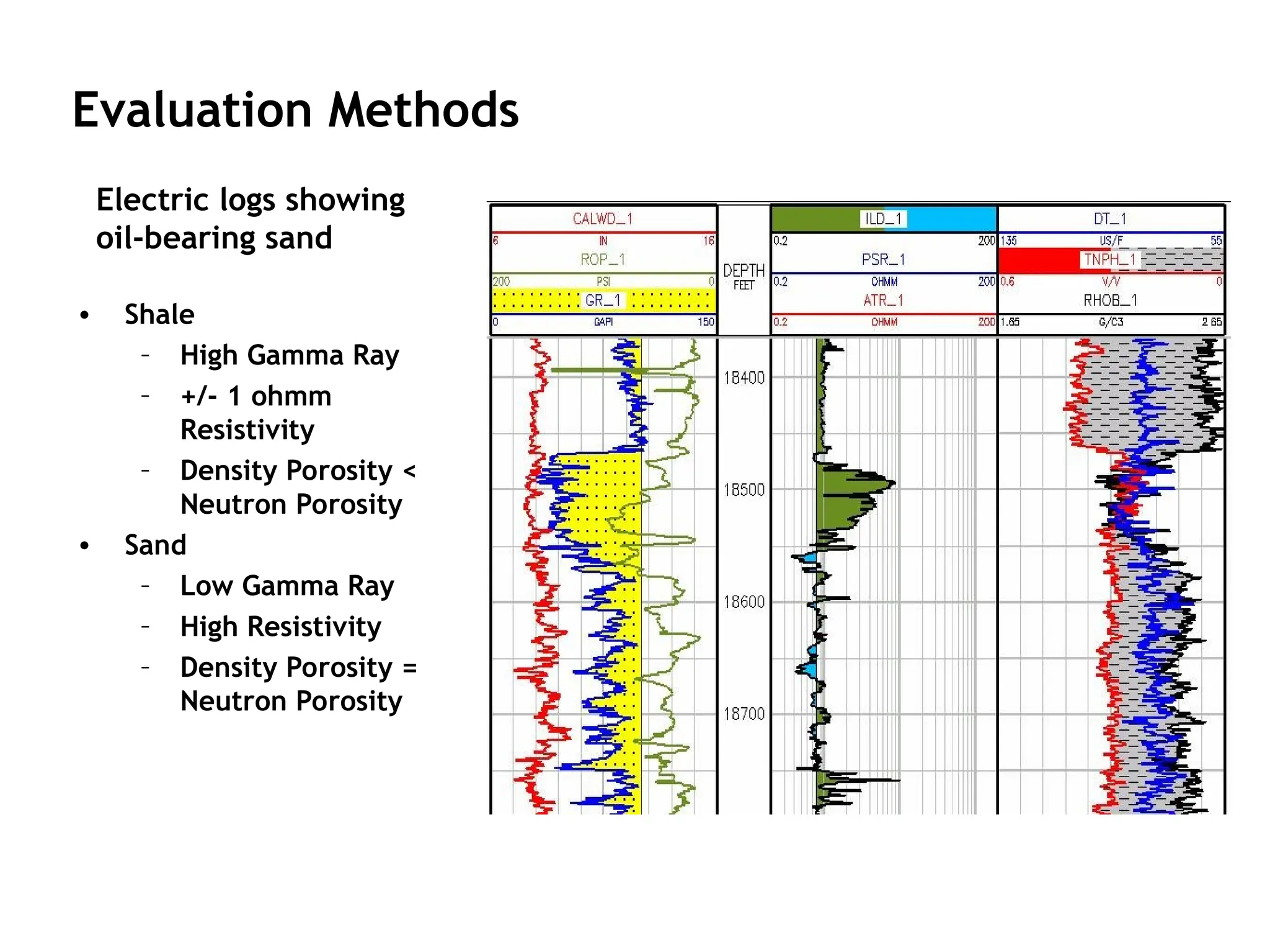
• Shale
– HighGamma Ray
– +/- 1 ohmm
Resistivity
– Density Porosity <
Neutron Porosity
• Sand
– Low Gamma Ray
– High Resistivity
– Density Porosity =
Neutron Porosity
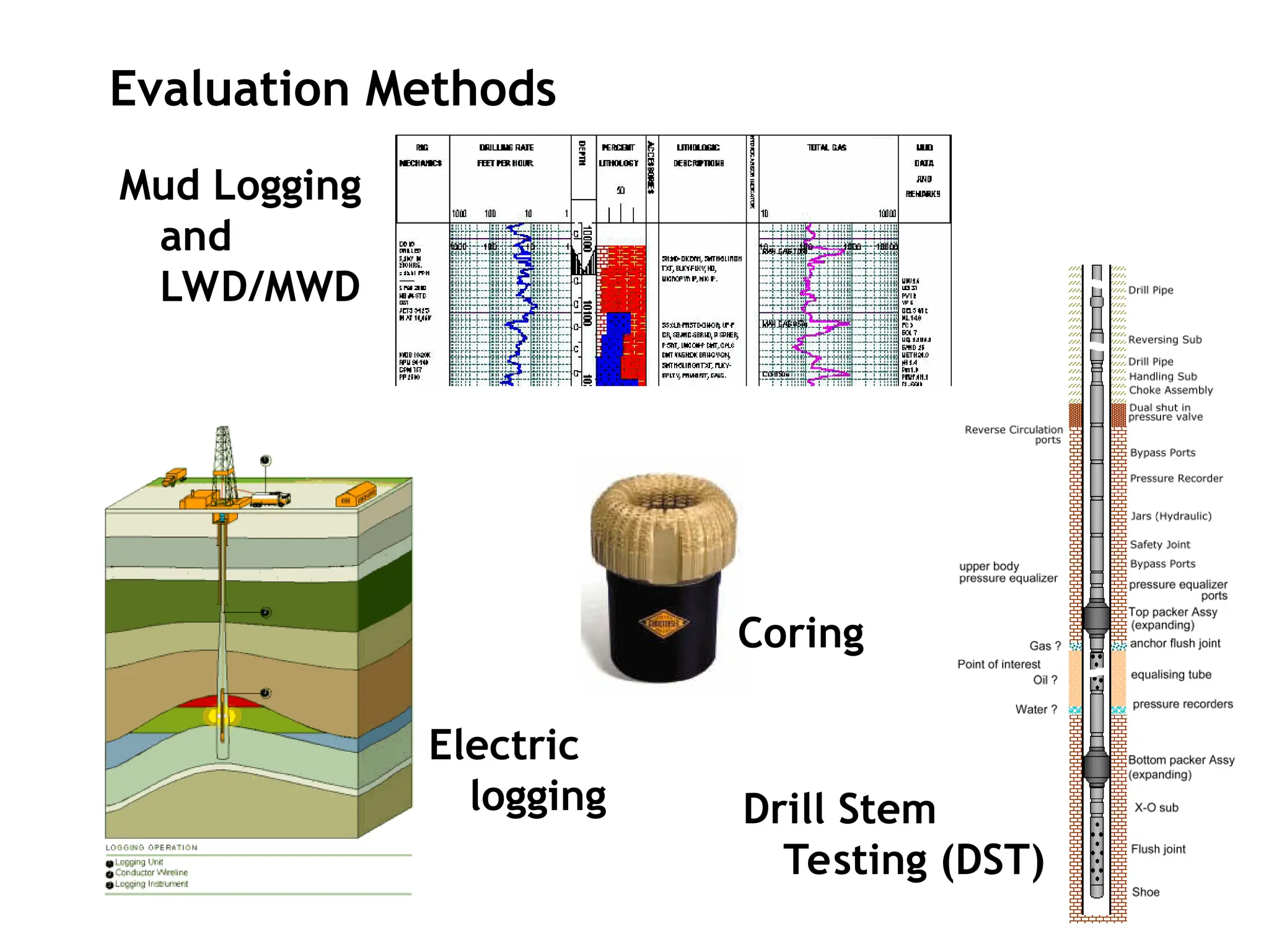
Evaluation Methods
Electric logs showing
oil-bearing sand
33.
Basic Completion
Equipment Terminology
Tubinghanger
Tubing spool
Surface Controlled
Subsurface Safety
Valve (SCSSV)
Gas lift valves
Production casing
Production packer
No Go Nipple
Re-entry guide
Blast joint
Seal bore extension
Seal assembly
Production tubing
Flow coupling
Landing Nipple
Circulating sleeve
34.
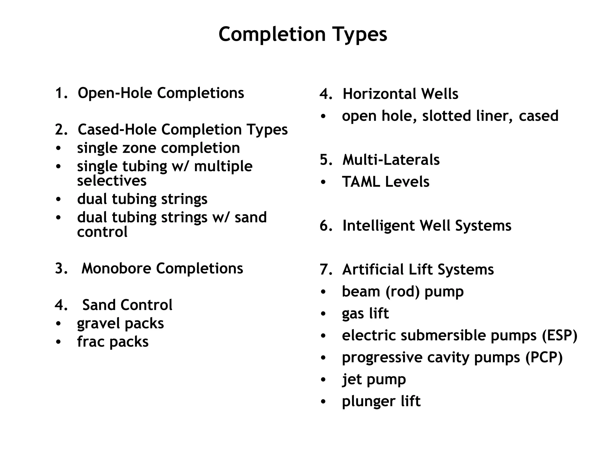
Completion Types
1. Open-HoleCompletions
2. Cased-Hole Completion Types
• single zone completion
• single tubing w/ multiple
selectives
• dual tubing strings
• dual tubing strings w/ sand
control
3. Monobore Completions
4. Sand Control
• gravel packs
• frac packs
4. Horizontal Wells
• open hole, slotted liner, cased
5. Multi-Laterals
• TAML Levels
6. Intelligent Well Systems
7. Artificial Lift Systems
• beam (rod) pump
• gas lift
• electric submersible pumps (ESP)
• progressive cavity pumps (PCP)
• jet pump
• plunger lift
Horizontal Wells
A “horizontalwell” or high angle well describes a well drilled
at an angle greater than 70º relative to vertical.
• Can connect natural fractures in carbonates.
• Prevent water/gas coning by reducing pressure draw down.
• Improves sweep efficiency through infill drilling, horizontal
injection for waterflood or EOR.
• Can enhance property value by increasing recovery in tight
gas reservoirs or thin sands or low permeability reservoirs.
• Location constraints limiting numerous wells.
37.
Horizontal Open-Hole GravelPack
Packer
Sand
Control Screen
Sized gravel
Casing Shoe
Unconsolidated Sandstone Reservoir
Underlying Water
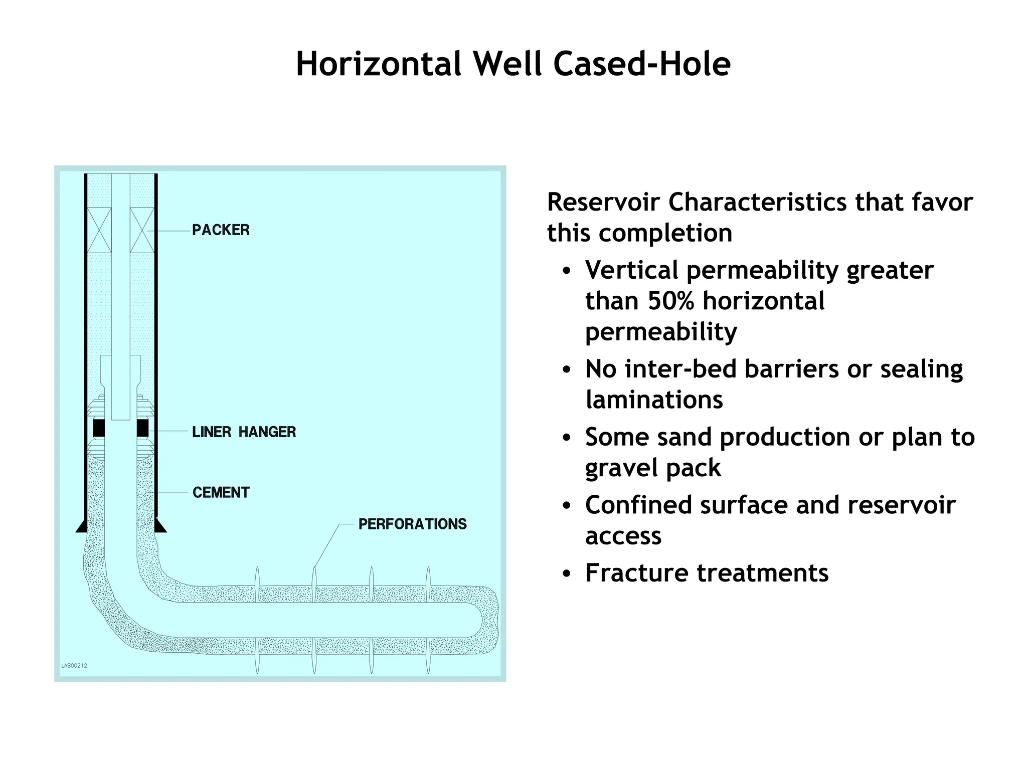
38.
Horizontal Well Cased-Hole
ReservoirCharacteristics that favor
this completion
• Vertical permeability greater
than 50% horizontal
permeability
• No inter-bed barriers or sealing
laminations
• Some sand production or plan to
gravel pack
• Confined surface and reservoir
access
• Fracture treatments
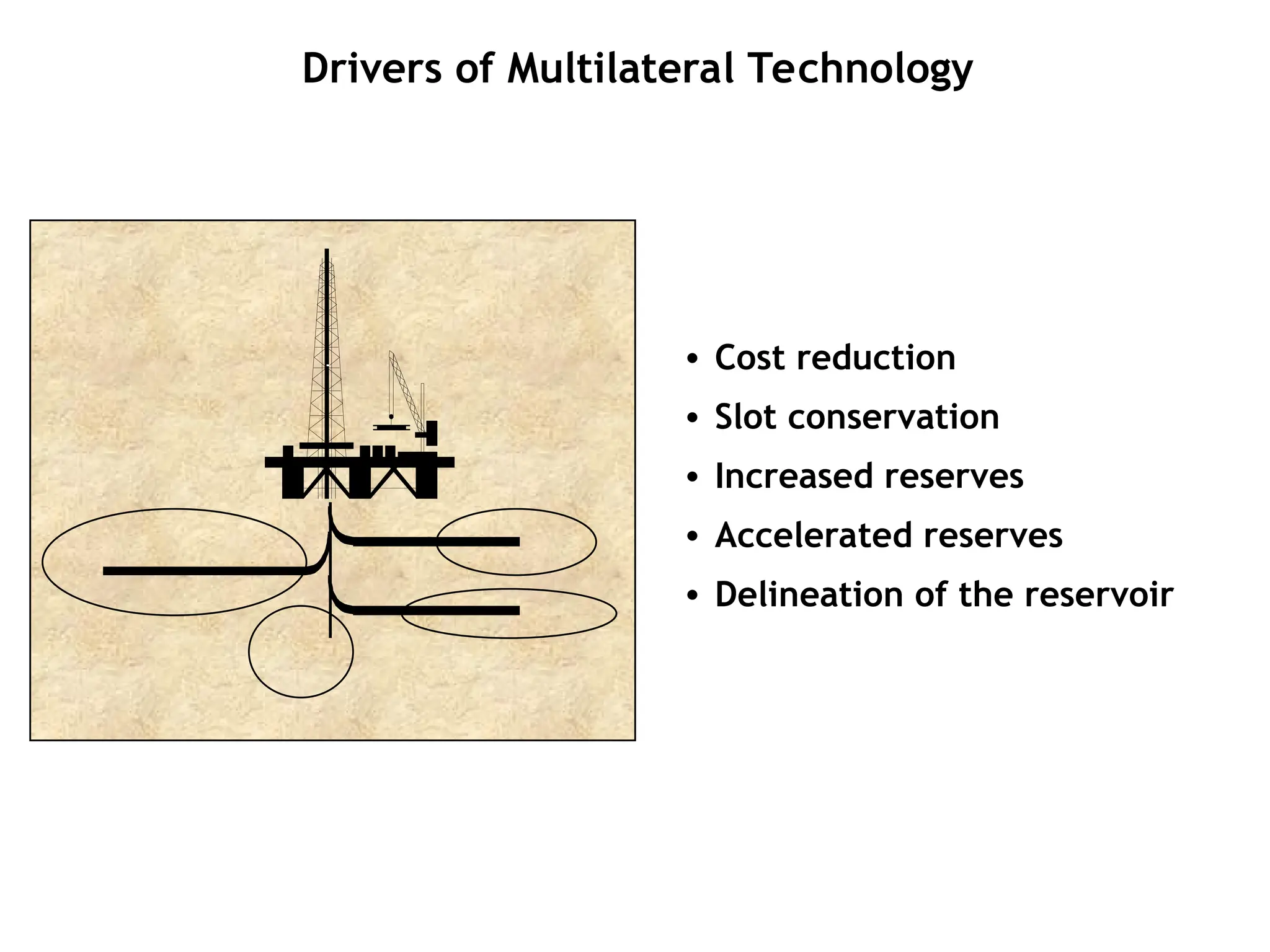
39.
Drivers of MultilateralTechnology
• Cost reduction
• Slot conservation
• Increased reserves
• Accelerated reserves
• Delineation of the reservoir
40.
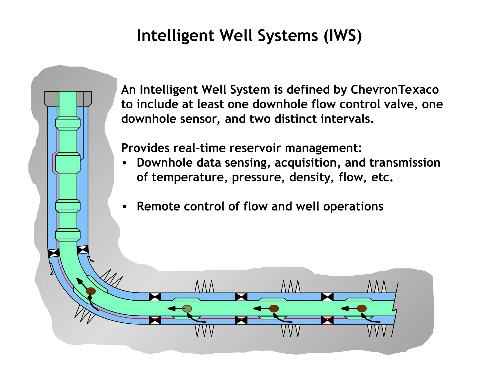
Intelligent Well Systems(IWS)
An Intelligent Well System is defined by ChevronTexaco
to include at least one downhole flow control valve, one
downhole sensor, and two distinct intervals.
Provides real-time reservoir management:
• Downhole data sensing, acquisition, and transmission
of temperature, pressure, density, flow, etc.
• Remote control of flow and well operations
41.
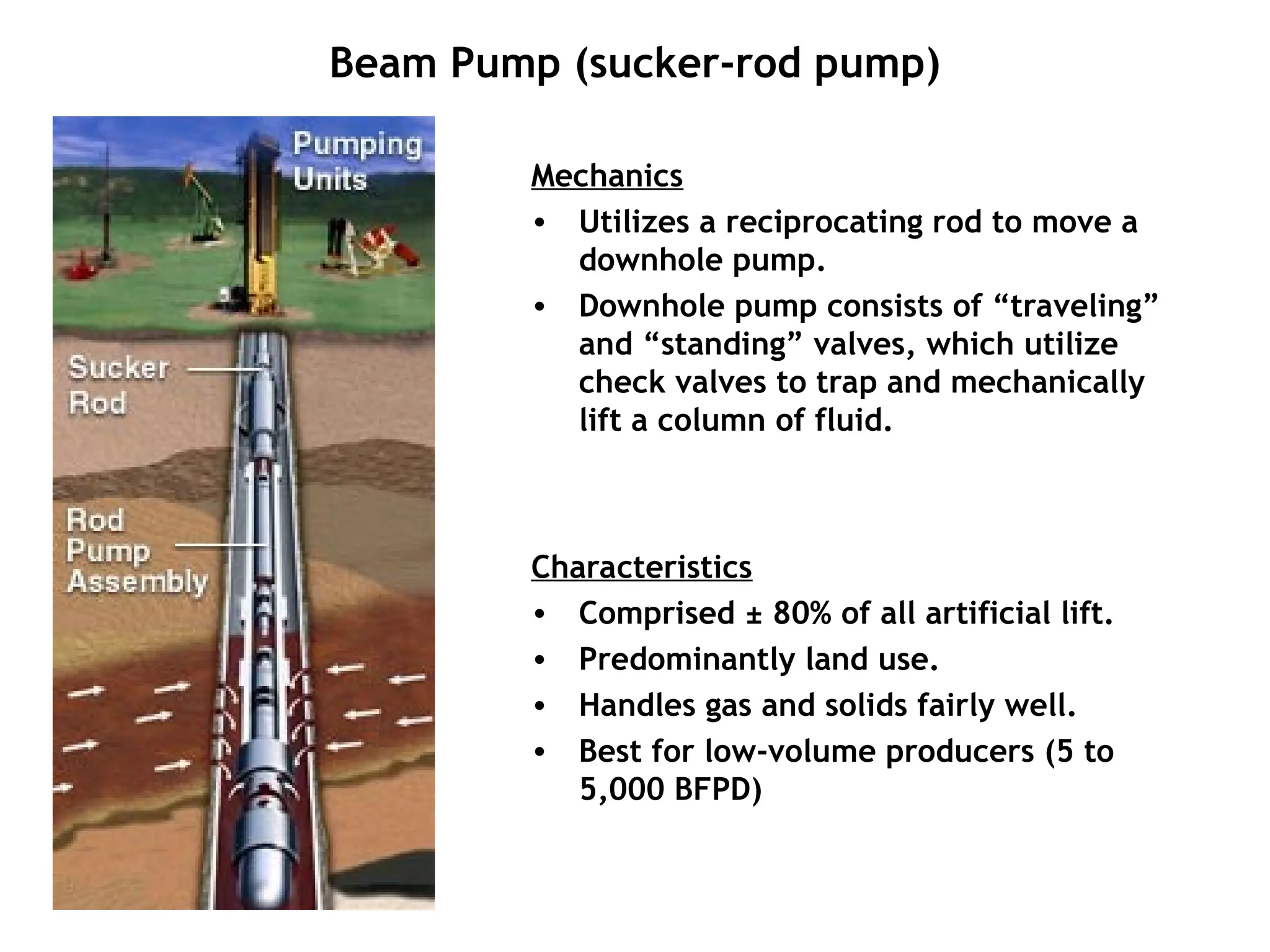
Beam Pump (sucker-rodpump)
Mechanics
• Utilizes a reciprocating rod to move a
downhole pump.
• Downhole pump consists of “traveling”
and “standing” valves, which utilize
check valves to trap and mechanically
lift a column of fluid.
Characteristics
• Comprised ± 80% of all artificial lift.
• Predominantly land use.
• Handles gas and solids fairly well.
• Best for low-volume producers (5 to
5,000 BFPD)
42.
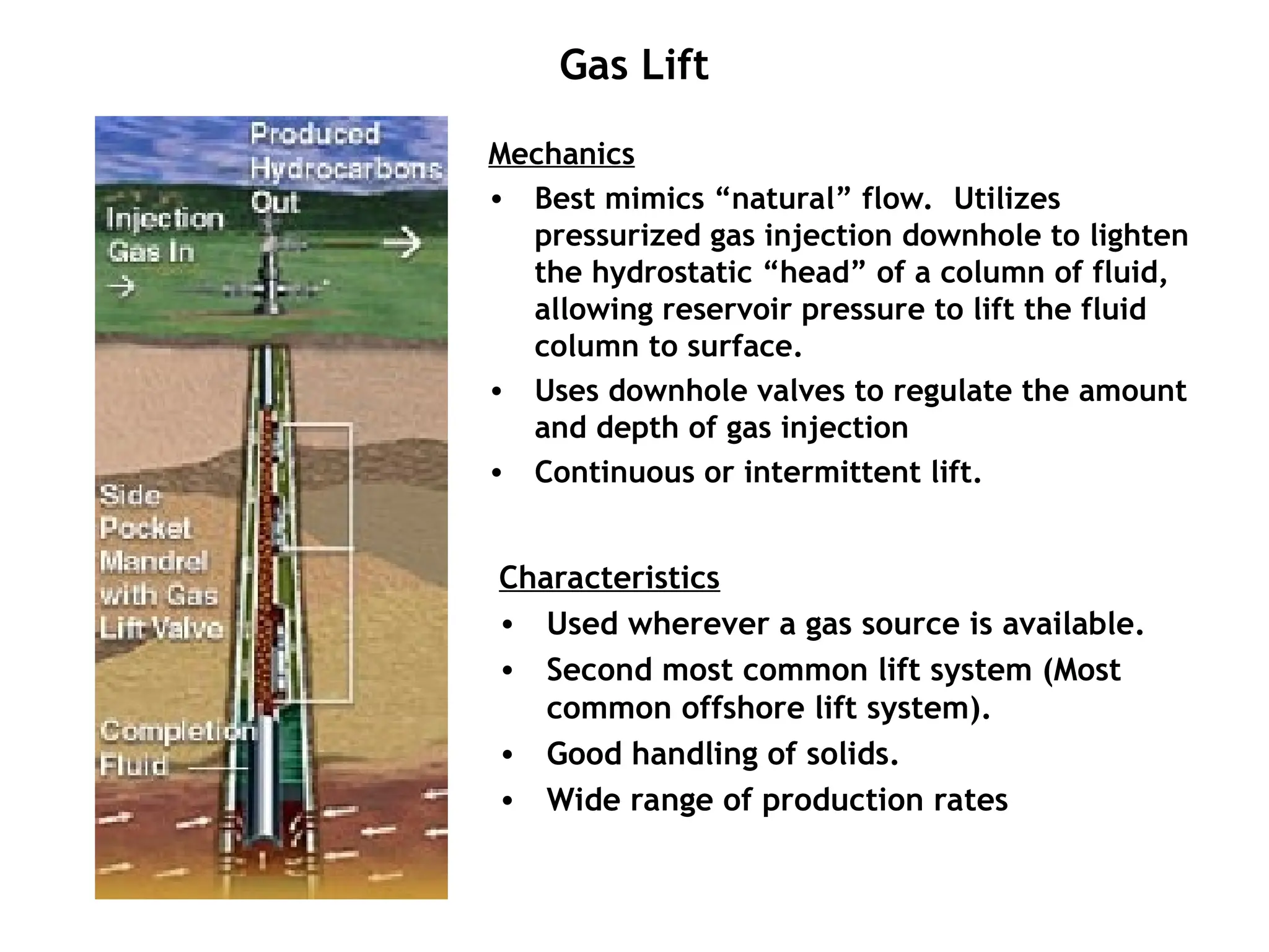
Gas Lift
Mechanics
• Bestmimics “natural” flow. Utilizes
pressurized gas injection downhole to lighten
the hydrostatic “head” of a column of fluid,
allowing reservoir pressure to lift the fluid
column to surface.
• Uses downhole valves to regulate the amount
and depth of gas injection
• Continuous or intermittent lift.
Characteristics
• Used wherever a gas source is available.
• Second most common lift system (Most
common offshore lift system).
• Good handling of solids.
• Wide range of production rates
43.
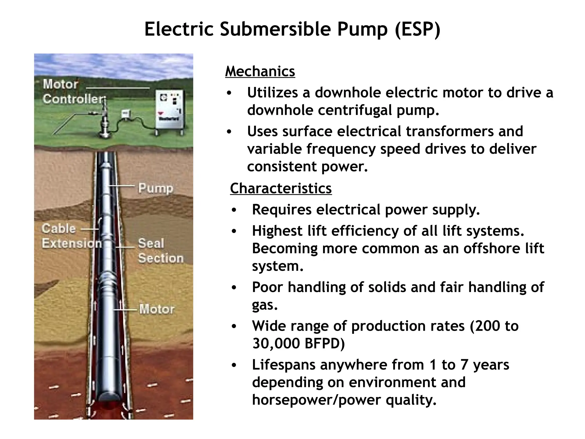
Electric Submersible Pump(ESP)
Mechanics
• Utilizes a downhole electric motor to drive a
downhole centrifugal pump.
• Uses surface electrical transformers and
variable frequency speed drives to deliver
consistent power.
Characteristics
• Requires electrical power supply.
• Highest lift efficiency of all lift systems.
Becoming more common as an offshore lift
system.
• Poor handling of solids and fair handling of
gas.
• Wide range of production rates (200 to
30,000 BFPD)
• Lifespans anywhere from 1 to 7 years
depending on environment and
horsepower/power quality.
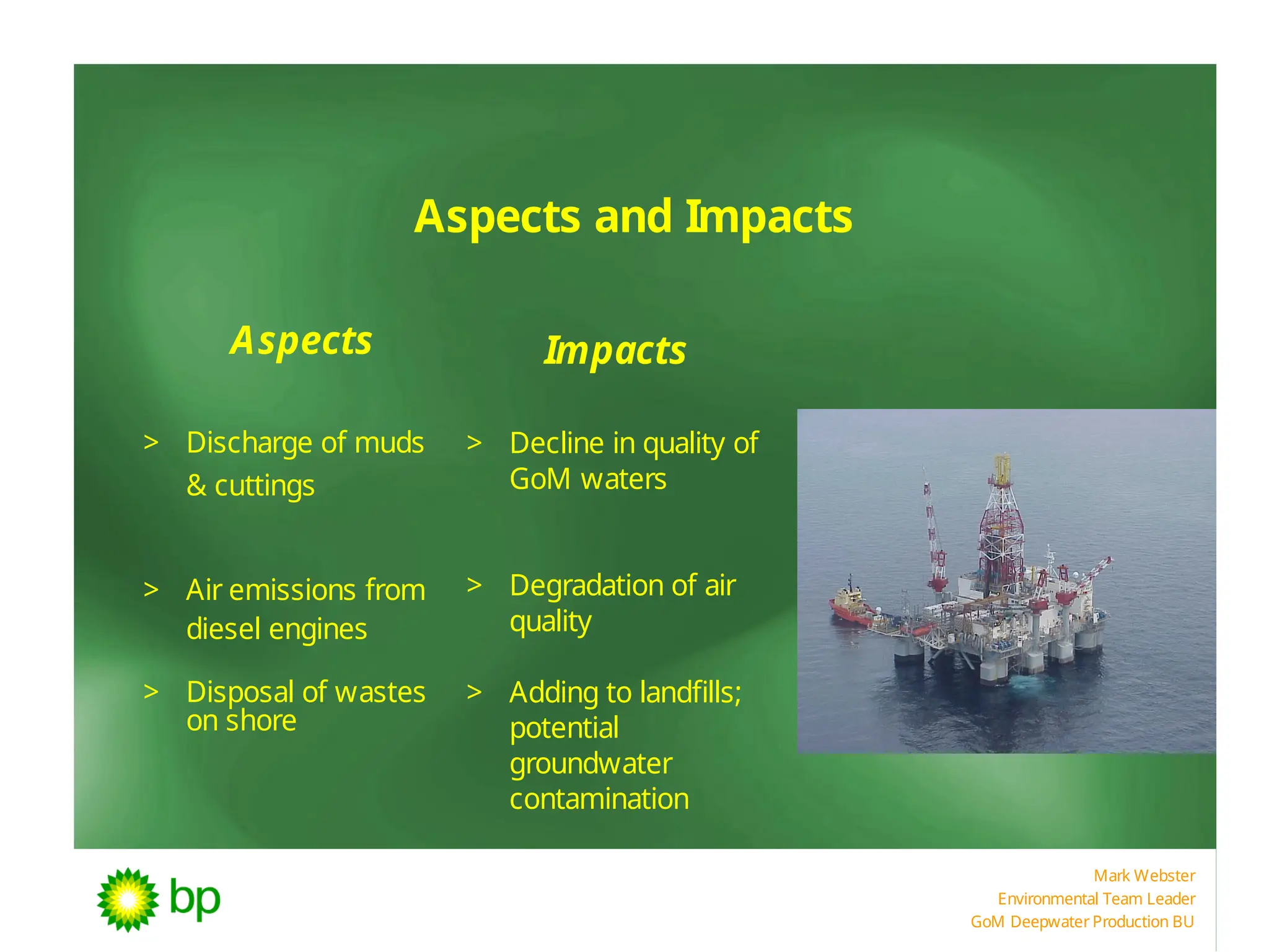
Mark Webster
Environmental TeamLeader
GoM Deepwater Production BU
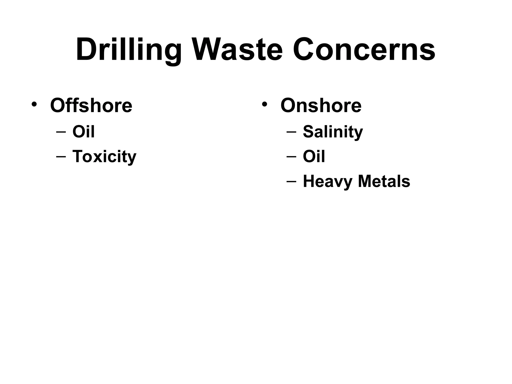
Aspects and Impacts
Aspects Impacts
> Discharge of muds
& cuttings
> Air emissions from
diesel engines
> Disposal of wastes
on shore
> Decline in quality of
GoM waters
> Degradation of air
quality
> Adding to landfills;
potential
groundwater
contamination
46.
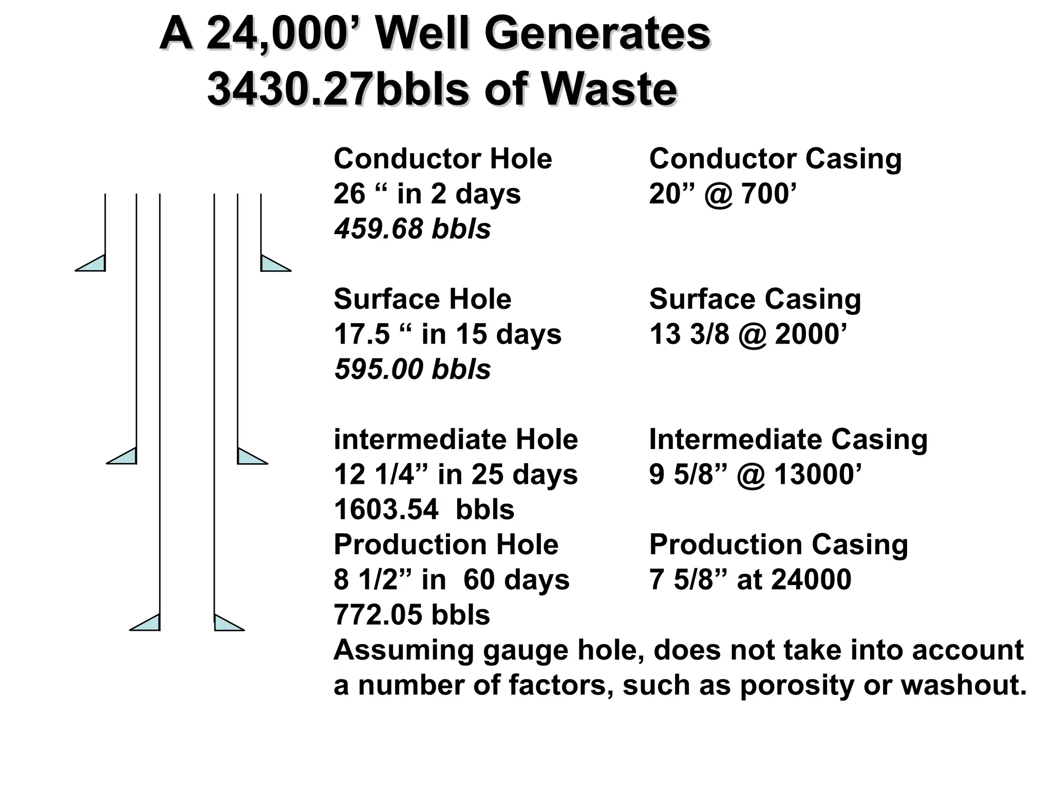
A 24,000’ WellGenerates
A 24,000’ Well Generates
3430.27bbls of Waste
3430.27bbls of Waste
Conductor Hole Conductor Casing
26 “ in 2 days 20” @ 700’
459.68 bbls
Surface Hole Surface Casing
17.5 “ in 15 days 13 3/8 @ 2000’
595.00 bbls
intermediate Hole Intermediate Casing
12 1/4” in 25 days 9 5/8” @ 13000’
1603.54 bbls
Production Hole Production Casing
8 1/2” in 60 days 7 5/8” at 24000
772.05 bbls
Assuming gauge hole, does not take into account
a number of factors, such as porosity or washout.
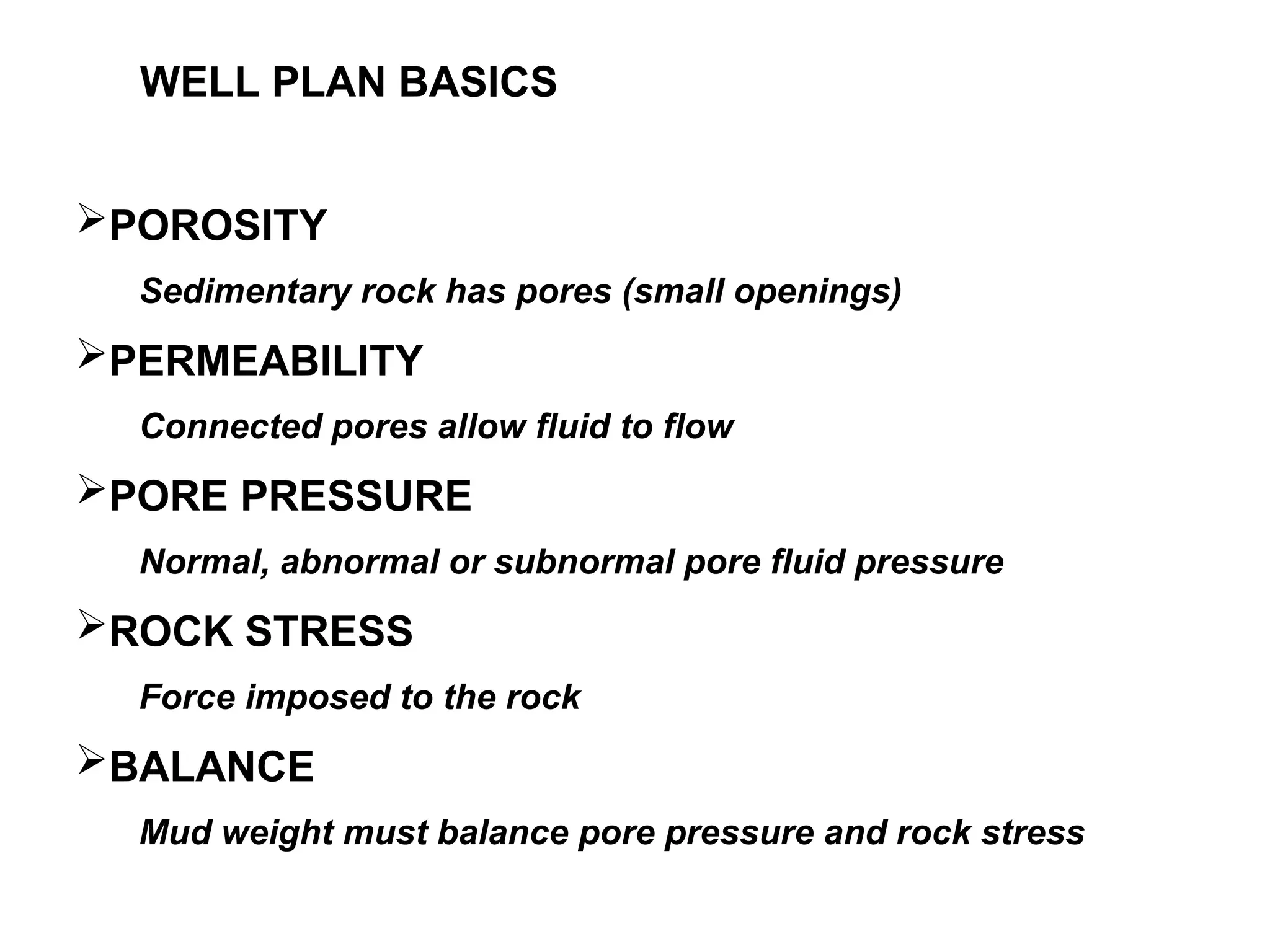
POROSITY
Sedimentary rock haspores (small openings)
PERMEABILITY
Connected pores allow fluid to flow
PORE PRESSURE
Normal, abnormal or subnormal pore fluid pressure
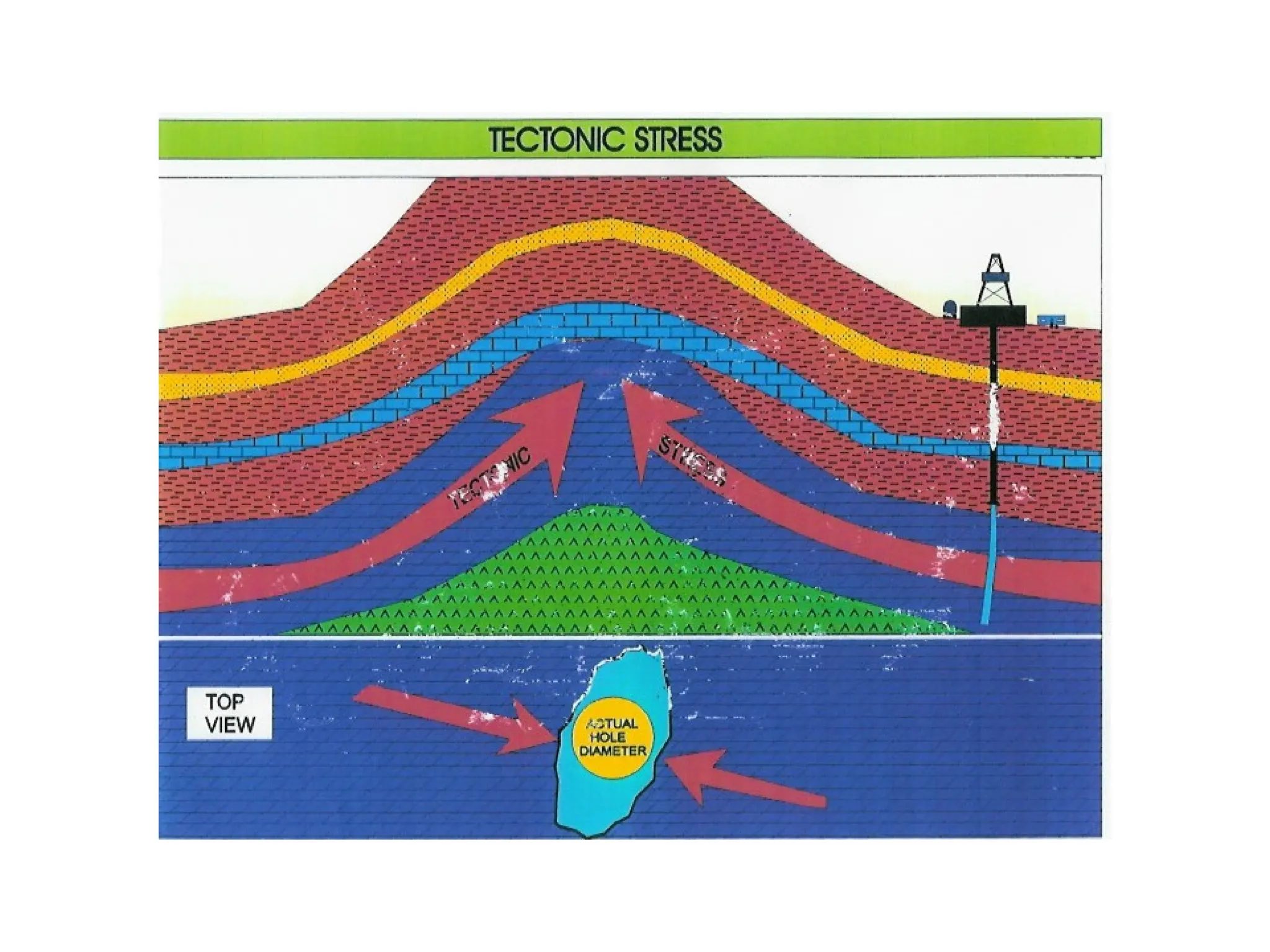
ROCK STRESS
Force imposed to the rock
BALANCE
Mud weight must balance pore pressure and rock stress
WELL PLAN BASICS
53.
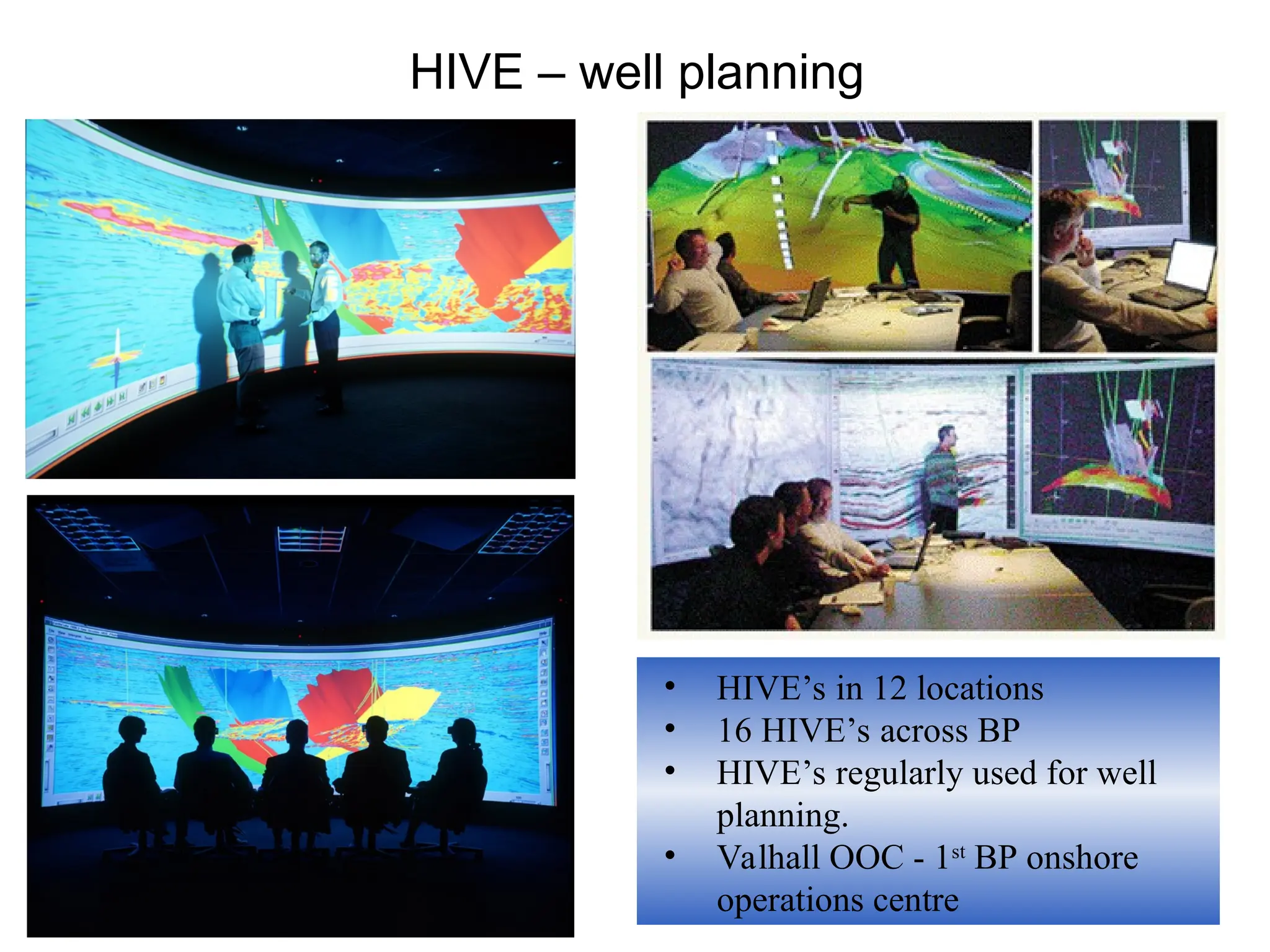
HIVE – wellplanning
• HIVE’s in 12 locations
• 16 HIVE’s across BP
• HIVE’s regularly used for well
planning.
• Valhall OOC - 1st
BP onshore
operations centre
54.
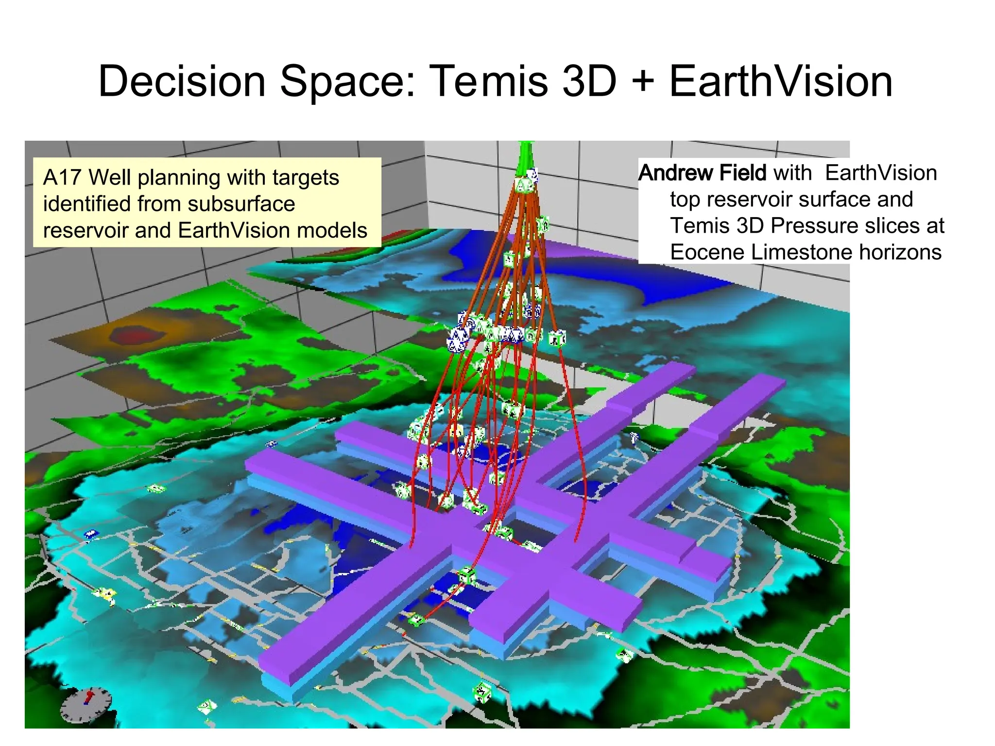
Decision Space: Temis3D + EarthVision
Andrew Field with EarthVision
top reservoir surface and
Temis 3D Pressure slices at
Eocene Limestone horizons
A17 Well planning with targets
identified from subsurface
reservoir and EarthVision models
55.
Top Reservoir
Rev H:
A17
A09: comparable trajectory
to Rev H A17
Comparison of Andrew A09 to
Planned Rev H (A17) Trajectory
VIEW NORTH
56.
Wellpath Rev H
TopReservoir
Andrew Platform
VIEW SOUTH
23”
16”
12 1/4”
Hole Sections Rev H (A17) Trajectory
Grouped drilling
NPT
Grouped drilling
NPT
23/32”
Grouped drilling
NPT
57.
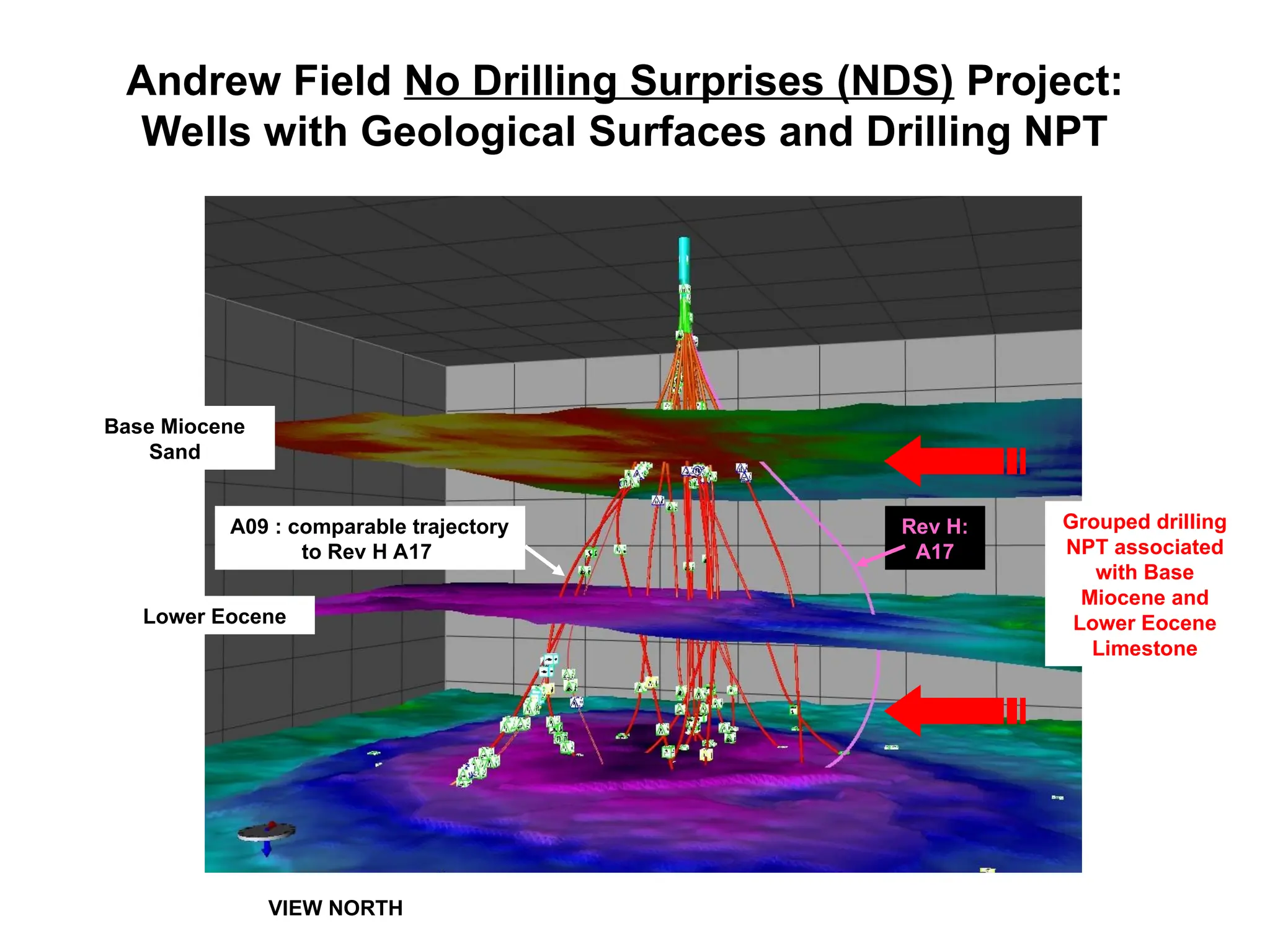
VIEW NORTH
Base Miocene
Sand
LowerEocene
Grouped drilling
NPT associated
with Base
Miocene and
Lower Eocene
Limestone
Rev H:
A17
Andrew Field No Drilling Surprises (NDS) Project:
Wells with Geological Surfaces and Drilling NPT
A09 : comparable trajectory
to Rev H A17
58.
VIEW NORTH
Base MioceneSand
Lower Eocene
12 1/4”
A09
NDS Lower 12 ¼”section :
Hole Cleaning, Tight Hole, Stuck
Pipe, Gas in Limestones,
Mudstones washing out.
Andrew NDS : Lower 12 ¼” Section
62.
Drilling Cost Estimation
•Deterministic - Single figure
• Probabilistic - Considers risk and uncertainty using
probabilities (objective, empirical, subjective) - Decision Trees,
Monte Carlo - Cost estimates are given with associated
probabilities, usually P10, P50 and P90
Both methods require base case estimation by hole intervals
Plot of Cost vs. Days – for tracking actual vs. estimated cost
Cost per Foot of offset wells for benchmarking and cost estimating
63.
C o un t r y : P r o j e c t :
D e l i v e r a b l e : C V P S t a g e :
C o s t E s t i m a t e :
B e s t i n C l a s s P e r f o r m a n c e :
#
S a n c t i o n A m o u n t : S a n c t i o n % i l e :
P r o m i s e ( P 1 0 - P 9 0 ) :
B e s t i n C l a s s P e r f o r m a n c e :
R i g r a t e 0 . 6 1
P r o j e c t S c o p e A s s u m p t i o n s : D r i l l i n g l e a r n i n g r a t e - 0 . 5 9
o S t u c k p i p e f r e q u e n c y 0 . 5 3
o L o s t c i r c u l a t i o n f r e q . 0 . 4 9
o W a i t i n g o n w e a t h e r 0 . 4 1
1 2 - 1 / 4 " h o l e R O P - 0 . 2 9
K e y R i s k A s s u m p t i o n s : 8 - 1 / 2 " h o l e R O P - 0 . 2 1
o A v g . s t u c k p i p e d u r a t i o n 0 . 1 8
o 1 7 - 1 / 2 " R O P - 0 . 1 5
o C o m p l e t i o n l e a r n i n g r a t e - 0 . 1 3
o
M M ( ± )
m i l l i o n
M e a n C o s t : $ 3 8 1
P r o j e c t D e t a i l s
I n p u t D a t a
M u l t i - w e l l e s t i m a t e w i t h l e a r n i n g . I n i t i a l p e r f o r m a n c e b a s e d o n f o u r p r e v i o u s E & A w e l l s . P l a t e a u p e r f o r m a n c e
b a s e d o n m u l t i p l e o f T e c h n i c a l L i m i t .
O r s i n o P h a s e 2 D e v e l o p m e n t
D e f i n e
1 2 o i l p r o d u c e r s + 2 w a t e r i n j e c t o r s
A v e r a g e o f t o p 1 0 % o f a l l I l l y r i a p l a t f o r m w e l l s , 1 9 9 7 - 2 0 0 0 , 2 0 0 1 R u s h m o r e d a t a .
T i m e & C o s t S u m m a r y
2 5 %
$ 4 7 6
$ 2 9 0
P 5 0
m i l l i o n
$ 3 7 9
M M -
W e l l s t e a m i n p l a c e 3 m t h s b e f o r e s p u d
M a j o r N P T r i s k s a r e p o s t - m i t i g a t i o n
F i r s t w e l l s p u d d e d i n 2 n d Q t r
d a y s (
1 2 6 5 P 2 7
K e y P e r f o r m a n c e I n d i c a t o r s P 5 0 P 9 0
)
4 6
5 4
4 8
D a y s / 1 0 K
2 2
3 6
2 7
D a y s / C o m p l e t i o n
R i g r a t e s p e r 2 0 0 1 a c t i v i t y l e v e l s
1 4 w e l l s ( 1 2 p r o d . + 2 i n j . )
2 g e o l . S i d e t r a c k s , 1 r e s p u d
" E x p l o r e r " c l a s s d r i l l i n g r i g
I l l y r i a
D r i l l i n g U n c e r t a i n t y S t a t e m e n t - S u m m a r y
A s s u m p t i o n s & R i s k s
B e s t i n C l a s s
P 1 0
4 4
2 1
- 1 - 0 . 5 0 0 . 5 1
Frequency C
hart
Cert ainty is 79. 74% f rom 1,200. 83 t o 1, 480. 69 days
.000
.006
.013
.019
.026
0
64
128
192
256
1, 000. 00 1, 175. 00 1, 350. 00 1, 525. 00 1,700. 00
10,000 Trials 30 Outliers
Forecast: Total Days
Frequency C
hart
Cert aint y is 80.09% from 290. 00 to 476. 67 million dollars
.000
.008
.015
.023
.030
0
75. 5
151
226. 5
302
150. 00 275. 00 400.00 525. 00 650. 00
10,000 Trials 10 Outliers
Forecast: Total C
ost
B i C
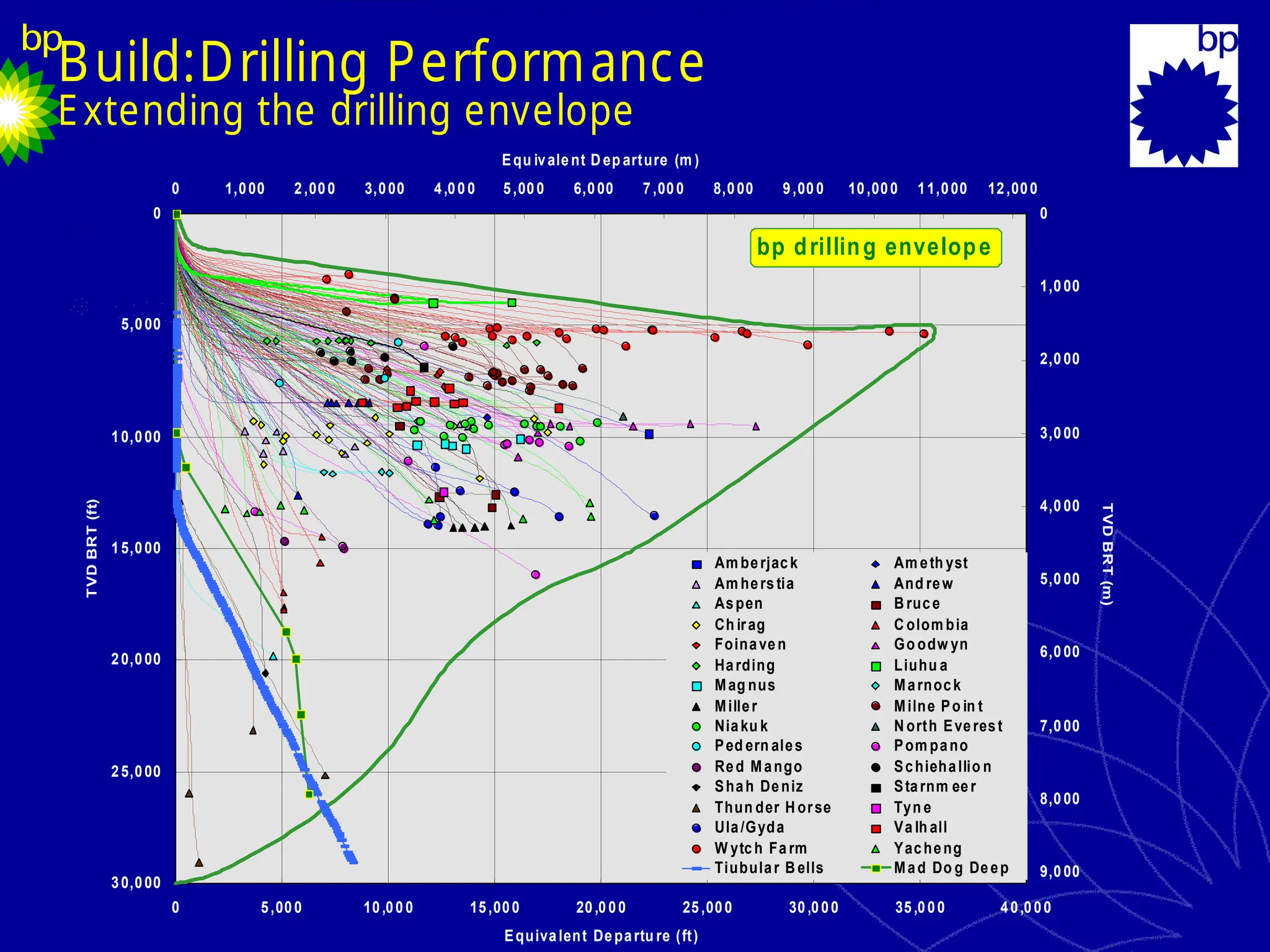
Build:Drilling Performance
Extending thedrilling envelope
0
5,000
10,000
15,000
20,000
25,000
30,000
0 5,000 10,000 15,000 20,000 25,000 30,000 35,000 40,000
Equivalent Departu re (ft)
TVD
BRT
(ft)
0
1,000
2,000
3,000
4,000
5,000
6,000
7,000
8,000
9,000
0 1,000 2,000 3,000 4,000 5,000 6,000 7,000 8,000 9,000 10,000 11,000 12,000
Equ ivalent D ep arture (m )
TVD
BRT
(m)
Am berjac k Am eth yst
Am hers tia And rew
Aspen B ruce
Ch irag C olom bia
Foinaven Go odw yn
Harding Liuhu a
Mag nus Marnock
Miller Milne Po in t
Niaku k N orth Everest
Ped ern ales Pom pano
Red Mango Schiehallio n
Shah Deniz Starnm eer
Thun der H orse Tyn e
Ula/Gyda Va lh all
W ytch Fa rm Yacheng
Tiubular B ells Mad Do g Deep
bp drilling envelope
Tubular Bells
Mad Do g Deep
Thunder
Horse
66.
Total
Depth
Pompano
Pompano Mars
Mars Ursa
Ursa
Empire
Empire
StateBldg.
State Bldg.
Diana
Diana
Hoover
Hoover Na Kika
Na Kika
Horn
Horn
Mtn
Mtn
Holstein
Holstein Atlantis
Atlantis
Mad
Mad
Dog
Dog
Thunder
Thunder
Horse
Horse
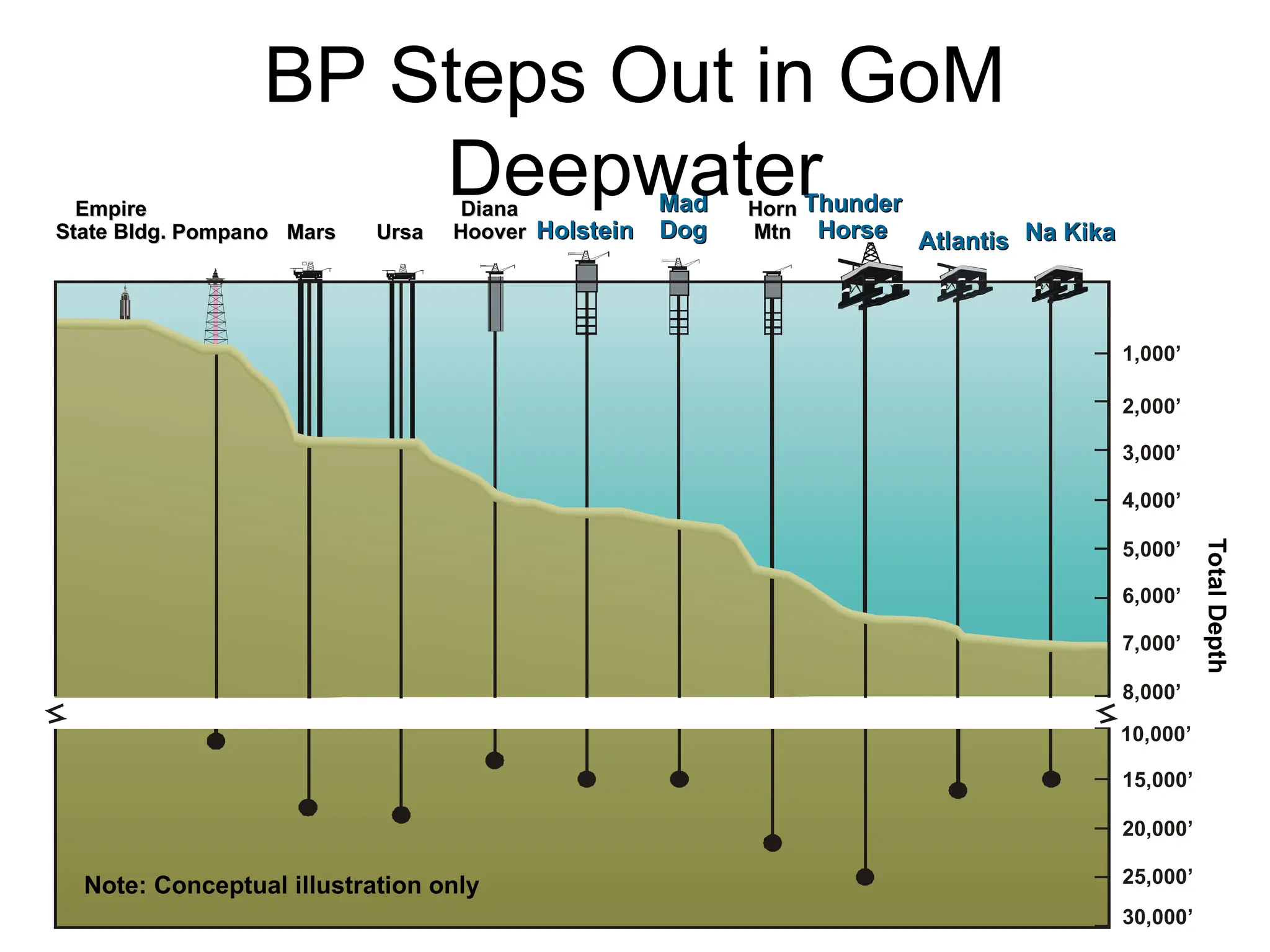
Note: Conceptual illustration only
10,000’
15,000’
20,000’
25,000’
30,000’
1,000’
2,000’
3,000’
4,000’
5,000’
6,000’
7,000’
8,000’
BP Steps Out in GoM
Deepwater
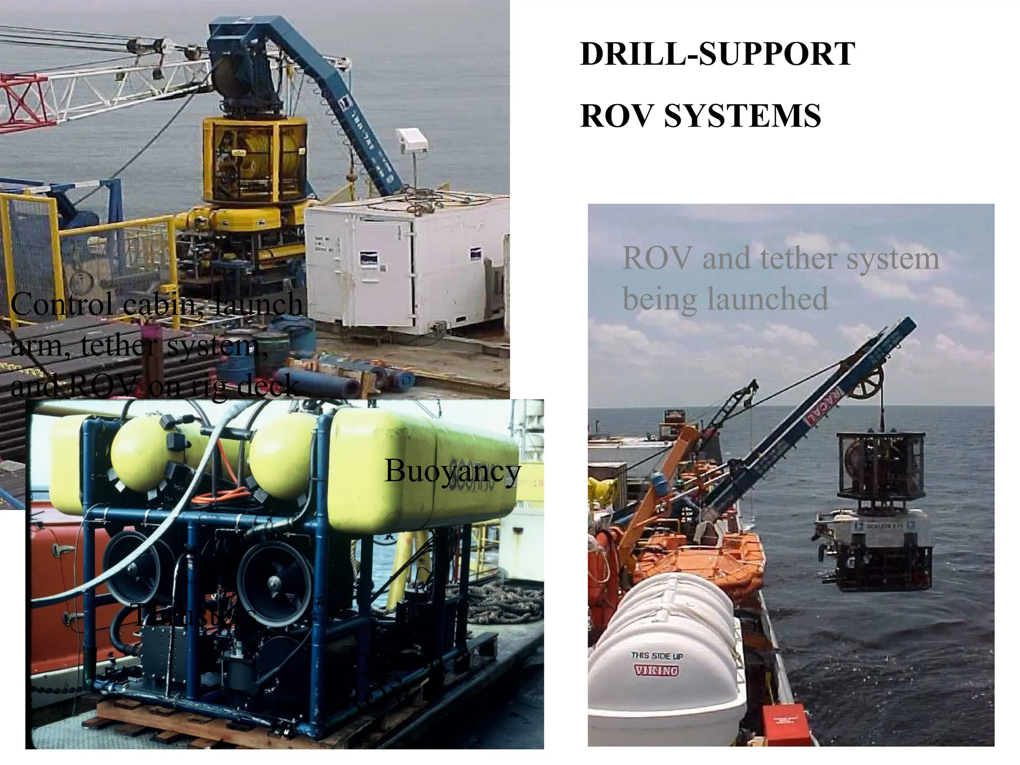
68.
ROV Launch
Control cabin,launch
arm, tether system,
and ROV on rig deck
ROV and tether system
being launched
Typical
ROV
Thrusters
Buoyancy
DRILL-SUPPORT
ROV SYSTEMS
Editor's Notes
#39 Cost Reduction
The purpose of the technology is to reduce CAPEX. The idea is simply to incur only the cost of rig time, tools, services, and equipment needed to drill and complete an average deviated lateral of 300-1500 feet. The costs of mobilization/ demobilization, casing, and drilling to top of zone will essentially be borne by the main wellbore. A possible cost reduction scenario would have the multilateral well providing twice the production, but only 1.5 times the cost of a monobore completion.
#54 Decision Space upgrade incorporates improved graphics with the ability to input the Earthvision structural model and the Temis Pressure cube.