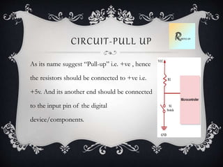
Every thing related to Pull up and Pull down resistor along with its basic need with some practical example, with its circuit, its applications, the definitions etc.
Opto-isolators or Opto-couplers, are made up of a light emitting device, and a light sensitive device, all wrapped up in one package, but with no electrical connection between the two, just a beam of light. Find different types of Opto couplers and its applications.
To understand the basic concepts of 8085 microprocessor, microcontroller. The students will also learn about the programming methods and integration of peripherals to the micro-controller.
This presentation provides a very brief overview of a Seven Segment Display.
For details on how to use Seven Segment Display with Arduino please visit www.harekrishnahub.com
Objectives
Understand the concept of amplifiers
Identify and apply internal transistor parameters
Understand and analyze common-emitter, common-collector and common-base amplifiers
Introduction
One of the primary uses of a transistor is to amplify ac signals. It has to be able to do it without distorting the original input.
Amplifier
The collector curves and load lines help us to relate the Q-point and its proximity to cutoff and saturation. The Q-point is best established where the signal variations do not cause the transistor to go into saturation or cutoff. For perfect amplifier Q-point must be in the middle of the active region.
Amplifier Operation
The region between cutoff and saturation is called the linear region. A transistor which operates in the linear region is called a linear amplifier. Note that only the ac component reaches the load because of the capacitive coupling and that the output is 180º out of phase with input.
The Common-Emitter Amplifier
The common-emitter amplifier exhibits high voltage gain and current gain. The output signal is 180º out of phase with the input signal.
Characteristics
Voltage gain -High
Current gain - High
Power gain - High
Input or output phase relationship - 180 degree
Input resistance - Low
Output resistance -High
Zero crossing detector detects how many times the input signal crossed the Zero value or Zero voltage level. Zero cross detector is basically a comparator circuit that compares the input sinusoidal signal or Sine wave signal with the zero voltage level, In other words, we can say that this detects the voltage changing from positive level to negative level and negative level to positive level. The output of the zero-cross detector changes when the input voltage crosses the zero level to High or High to zero.
Lab 12 – Latches and Flip-Flops Mugisha OmaryLab 12 .docxDIPESH30
Lab 12 – Latches and Flip-Flops
Mugisha Omary
Lab 12 – Latches and Flip-Flops
Laboratory Report for EENG 3302
College of Engineering and Computer Science
Department of Electrical Engineering
University of Texas at Tyler
Houston, Texas
December 10, 2013
Mugisha Omary
Group Members
Jonathan Vidana
Hamza Ahmad
Shamir Mohammed
Abstract
The purpose of this experiment is to be able to understand how latches operate and their similarities and differences to flip-flops by using NAND gates.
I. Project description
The latch is a digital memory circuit that can remain in the state in which it was set even after the input signals are removed. Latches are basically similar to flip-flops because they are bi-stable devices that can reside in either of two states by virtue of a feedback arrangement, in which the outputs are connected back to the opposite inputs. The main difference between latches and flip-flops is in the method used for changing their state. Latches are level-triggered and flip-flops are edge-triggered.
After completion of this experiment, we will be able to understand the operation of laches and similarities and differences to flip-flops.
II. Theoretical background
When the clock is high the input D propogates to the output Q as it is and when the clock is low the output is held(irrespective of the changes in input D).This definition indicates that D latch can be implemented as a multiplexer with clock signal as the select input of multiplexer. Applying analogy , we realise that when clock=1 the input to the CMOS pass transistor should be D and when clock=0 the input to the pass transistor should be value of D just before the transition of clock from 1 to 0.To obtain the value of D just before transition a buffer is needed.The final design is given below:
Figure 1-D latch
In digital systems, the types of circuits that can retain previous input levels after original inputs are removed are called sequential circuits.
The set-reset (S-R) latch has two input, a SET input and a RESET input, and two outputs, Q and Q. When the Q output is a 1, the latch is SET; when the Q output is a 0, the latch is RESET.
When an active-LOW input is applied to the SET input, the latch goes to the SET (Q = 1) condition and remains that way until an active-LOW signal is applied to the RESET input. Then it goes to the RESET (Q = 0) condition.
An invalid condition occurs if active-LOW inputs are applied at the same time to both the SET and the RESET inputs. During the time both the inputs are active, the Q output is 1 and the output is a 1 (clearly an invalid condition). When both inputs go HIGH (inactive), the S-R latch stays latched in one state or the other. However, the exact state is not easily predictable. The final state of the latch depends on which input was active last as two inputs went to the inactive state.
Many applications require that the latch be enabled or gated by another source, called a clock ...
Different Types of Voltage Regulators with Working Principleelprocus
A voltage regulator is designed to automatically maintain a constant voltage level. Know more about different types of voltage regulators and their working principle . Learn its Advantages, disadvantages, circuit theory and applications.
Immunizing Image Classifiers Against Localized Adversary Attacksgerogepatton
This paper addresses the vulnerability of deep learning models, particularly convolutional neural networks
(CNN)s, to adversarial attacks and presents a proactive training technique designed to counter them. We
introduce a novel volumization algorithm, which transforms 2D images into 3D volumetric representations.
When combined with 3D convolution and deep curriculum learning optimization (CLO), itsignificantly improves
the immunity of models against localized universal attacks by up to 40%. We evaluate our proposed approach
using contemporary CNN architectures and the modified Canadian Institute for Advanced Research (CIFAR-10
and CIFAR-100) and ImageNet Large Scale Visual Recognition Challenge (ILSVRC12) datasets, showcasing
accuracy improvements over previous techniques. The results indicate that the combination of the volumetric
input and curriculum learning holds significant promise for mitigating adversarial attacks without necessitating
adversary training.
CW RADAR, FMCW RADAR, FMCW ALTIMETER, AND THEIR PARAMETERSveerababupersonal22
It consists of cw radar and fmcw radar ,range measurement,if amplifier and fmcw altimeterThe CW radar operates using continuous wave transmission, while the FMCW radar employs frequency-modulated continuous wave technology. Range measurement is a crucial aspect of radar systems, providing information about the distance to a target. The IF amplifier plays a key role in signal processing, amplifying intermediate frequency signals for further analysis. The FMCW altimeter utilizes frequency-modulated continuous wave technology to accurately measure altitude above a reference point.
Harnessing WebAssembly for Real-time Stateless Streaming PipelinesChristina Lin
Traditionally, dealing with real-time data pipelines has involved significant overhead, even for straightforward tasks like data transformation or masking. However, in this talk, we’ll venture into the dynamic realm of WebAssembly (WASM) and discover how it can revolutionize the creation of stateless streaming pipelines within a Kafka (Redpanda) broker. These pipelines are adept at managing low-latency, high-data-volume scenarios.
NUMERICAL SIMULATIONS OF HEAT AND MASS TRANSFER IN CONDENSING HEAT EXCHANGERS...ssuser7dcef0
Power plants release a large amount of water vapor into the
atmosphere through the stack. The flue gas can be a potential
source for obtaining much needed cooling water for a power
plant. If a power plant could recover and reuse a portion of this
moisture, it could reduce its total cooling water intake
requirement. One of the most practical way to recover water
from flue gas is to use a condensing heat exchanger. The power
plant could also recover latent heat due to condensation as well
as sensible heat due to lowering the flue gas exit temperature.
Additionally, harmful acids released from the stack can be
reduced in a condensing heat exchanger by acid condensation. reduced in a condensing heat exchanger by acid condensation.
Condensation of vapors in flue gas is a complicated
phenomenon since heat and mass transfer of water vapor and
various acids simultaneously occur in the presence of noncondensable
gases such as nitrogen and oxygen. Design of a
condenser depends on the knowledge and understanding of the
heat and mass transfer processes. A computer program for
numerical simulations of water (H2O) and sulfuric acid (H2SO4)
condensation in a flue gas condensing heat exchanger was
developed using MATLAB. Governing equations based on
mass and energy balances for the system were derived to
predict variables such as flue gas exit temperature, cooling
water outlet temperature, mole fraction and condensation rates
of water and sulfuric acid vapors. The equations were solved
using an iterative solution technique with calculations of heat
and mass transfer coefficients and physical properties.
HEAP SORT ILLUSTRATED WITH HEAPIFY, BUILD HEAP FOR DYNAMIC ARRAYS.
Heap sort is a comparison-based sorting technique based on Binary Heap data structure. It is similar to the selection sort where we first find the minimum element and place the minimum element at the beginning. Repeat the same process for the remaining elements.
Water billing management system project report.pdfKamal Acharya
Our project entitled “Water Billing Management System” aims is to generate Water bill with all the charges and penalty. Manual system that is employed is extremely laborious and quite inadequate. It only makes the process more difficult and hard.
The aim of our project is to develop a system that is meant to partially computerize the work performed in the Water Board like generating monthly Water bill, record of consuming unit of water, store record of the customer and previous unpaid record.
We used HTML/PHP as front end and MYSQL as back end for developing our project. HTML is primarily a visual design environment. We can create a android application by designing the form and that make up the user interface. Adding android application code to the form and the objects such as buttons and text boxes on them and adding any required support code in additional modular.
MySQL is free open source database that facilitates the effective management of the databases by connecting them to the software. It is a stable ,reliable and the powerful solution with the advanced features and advantages which are as follows: Data Security.MySQL is free open source database that facilitates the effective management of the databases by connecting them to the software.
Final project report on grocery store management system..pdfKamal Acharya
In today’s fast-changing business environment, it’s extremely important to be able to respond to client needs in the most effective and timely manner. If your customers wish to see your business online and have instant access to your products or services.
Online Grocery Store is an e-commerce website, which retails various grocery products. This project allows viewing various products available enables registered users to purchase desired products instantly using Paytm, UPI payment processor (Instant Pay) and also can place order by using Cash on Delivery (Pay Later) option. This project provides an easy access to Administrators and Managers to view orders placed using Pay Later and Instant Pay options.
In order to develop an e-commerce website, a number of Technologies must be studied and understood. These include multi-tiered architecture, server and client-side scripting techniques, implementation technologies, programming language (such as PHP, HTML, CSS, JavaScript) and MySQL relational databases. This is a project with the objective to develop a basic website where a consumer is provided with a shopping cart website and also to know about the technologies used to develop such a website.
This document will discuss each of the underlying technologies to create and implement an e- commerce website.
We have compiled the most important slides from each speaker's presentation. This year’s compilation, available for free, captures the key insights and contributions shared during the DfMAy 2024 conference.
2. WHAT IT IS?
When using any kind of “open” inputs with an
Arduino/Microcontrollers/logic gates such as switches,
push buttons, reed relays, and some sensors, a pull-up or
pull –down resistor is needed for its reliable operation.
These resistors hold the I/O pin at a known value until
the switch forces the I/O pin to a different known value.
3. DEFINITION
Pull up:- The Pull-up resistor pulls the signal to high state of
the input pin, unless it is driven low.
Pull-up defaults to a HIGH. It’s value is LOW when active.
Pull down:- A pull-down resistor pulls the signal to low state
unless it is driven high.
Pull-down defaults to a LOW. It’s value is HIGH when active.
4. DEFINITION (ANOTHER)
Pull up:- Pull-up resistors are resistors which are used to ensure
that a wire is pulled to a high logical level in the absence of
an input signal.
Pull down:- Pull-down resistors are resistors which are used to
ensure that a wire is pulled down to a low logical level in the
absence of an input signal..
5. WHY WE USE THEM?
To prevent accidental switching of digital circuits/ICs,
any of the unconnected inputs called “floating
inputs”, should be tied to a logic “1” or logic “0” as
appropriate for the circuit.
6. PRACTICAL EXPERIENCE
Normally the input pins of the Digital gates/ICs/
Controllers etc. behaves as a “floating pin (there value keep
varying, 0 or 1)”. Because of the presence of the EMI
waves/noise signal etc. in surrounding, the input value of these
pins constantly keep varying on their own. We can either use a
Multimeter or a CRO to visualize these variations. That’s why
we use Pull-up or down resistors to fix their values to 0 or 1.
7. CIRCUIT-PULL UP
As its name suggest “Pull-up” i.e. +ve , hence
the resistors should be connected to +ve i.e.
+5v. And its another end should be connected
to the input pin of the digital
device/components.
8. CIRCUIT-PULL DOWN
As its name suggest “Pull-down” i.e. -ve ,
hence the resistors should be connected to
-ve or ground i.e. 0v. And its another end should be
connected to the input pin of the digital
device/components.
9. FORMULA FOR (PULL UP)
Q. Suppose we have a logic circuit where
the supply source is 3.3V and the
acceptable logic high voltage is 3V, and we
could sink a current maximum of 30uA,
then we can choose the pull-up resistor
using the formula like this way-
10. FORMULA FOR (PULL DOWN)
Q. Now, If we consider the same example
stated in the previous question, where the
circuit accepts 1V as the maximum logic
Low voltage and could source up to
200uA of current then the Pull-down
resistor will be,
11. APPLICATIONS (1)
Pull-up and Pull-down resistors are frequently used
in Interfacing devices like interfacing a switch to
microcontroller.
These resistors are often used in A/D converters to
provide a controlled flow of current into a resistive sensor.
12. APPLICATIONS (2)
Pull-up and pull-down resistors are used in I2C protocol
bus, wherein the pull-up resistors are used to allow a single
pin to act as an I/P or O/P.