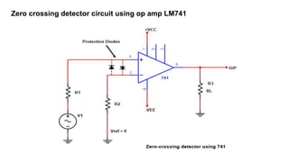
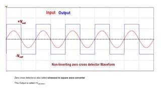
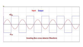
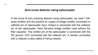
What is Zero crossing detector
(Zero cross detector circuit, working and applications)
A guide by Aman bharti (www.circuitspedia.com)
Zero crossing detector detects how many times the input
signal crossed the Zero value or Zero voltage level. Zero
cross detector is basically a comparator circuit that compares
the input sinusoidal signal or Sine wave signal with the zero
voltage level, In other words, we can say that this detects the
voltage changing from positive level to negative level and
negative level to positive level. The output of the zero-cross
detector changes when the input voltage crosses the zero level
to High or High to zero.
A Zero cross detector compares the input signal with the zero reference voltage
(Vref). It changes the output Either +Vsat or –Vsat by switching from LOW to HIGH
or Vice versa. When the input crosses zero reference voltage. when the input
voltage signal is even a little higher or Lower than 0v the output will quickly
change. A zero-crossing detector can be made using a general-purpose
operational-Amplifier, Using Opto-coupler or using transistors.
Zero crossing detector circuit using op amp LM741
NON-Inverting Zero cross detector
If Reference voltage zero set on the inverting input terminal
means the inverting terminal is grounded and Input signal
applied at NON-Inverting terminal. +Vcc are connected with
pin 7 and -VEE with pin 4, 6 is the output pin is and a load
resistor RL connected with output to ground, even a little
amount of input voltage in higher than zero (Reference
voltage), then the output will HIGH. When the input goes on
increasing from zero to positive then the output voltage goes
into Positive saturation.
Zero cross detector is also called sinewave to square wave converter
This Output is called +Vsaturation .
Inverting Zero cross detector
If input voltage applied at the Inverting terminal and reference voltage are
given on NON-Inverting terminal or Non-inverting terminal is grounded,
when even also a little amount of input voltage is higher than zero volts
the output will switch to LOW. When the input goes on increasing from
zero to positive then the output voltage goes into Negative saturation.
And this LOW output is called –Vsaturation.
Zero-cross detector using optocoupler
In the circuit of zero crossing detector using optocoupler, we used 1 full-
wave rectifier and the positive dc supply of bridge rectifier connected to
cathode pin of optocoupler input. Output is connected with the collector
pin of the optocoupler. Here full-wave bridge rectifier used without the
filter capacitor. The emitter pin of the optocoupler is connected with the
DC ground. VCC connected with the collector pin. A resistor connected
with a collector is also called a Pull-up resistor.
Uses of zero cross detector (ZCD)
● ZCD as Phasemeter
● ZCD as Time Marker Generator
● AC power controllers
● Induction motor speed control and soft starters
● Thyristor firing angle control using Arduino etc
· LOGIC GATES
·
Also read
· Sample and Hold circuit
Thank you
Please like this slide

zero cross detector.pptx

  • 1.
    What is Zerocrossing detector (Zero cross detector circuit, working and applications) A guide by Aman bharti (www.circuitspedia.com)
  • 2.
    Zero crossing detectordetects how many times the input signal crossed the Zero value or Zero voltage level. Zero cross detector is basically a comparator circuit that compares the input sinusoidal signal or Sine wave signal with the zero voltage level, In other words, we can say that this detects the voltage changing from positive level to negative level and negative level to positive level. The output of the zero-cross detector changes when the input voltage crosses the zero level to High or High to zero.
  • 4.
    A Zero crossdetector compares the input signal with the zero reference voltage (Vref). It changes the output Either +Vsat or –Vsat by switching from LOW to HIGH or Vice versa. When the input crosses zero reference voltage. when the input voltage signal is even a little higher or Lower than 0v the output will quickly change. A zero-crossing detector can be made using a general-purpose operational-Amplifier, Using Opto-coupler or using transistors.
  • 5.
    Zero crossing detectorcircuit using op amp LM741
  • 6.
    NON-Inverting Zero crossdetector If Reference voltage zero set on the inverting input terminal means the inverting terminal is grounded and Input signal applied at NON-Inverting terminal. +Vcc are connected with pin 7 and -VEE with pin 4, 6 is the output pin is and a load resistor RL connected with output to ground, even a little amount of input voltage in higher than zero (Reference voltage), then the output will HIGH. When the input goes on increasing from zero to positive then the output voltage goes into Positive saturation.
  • 8.
    Zero cross detectoris also called sinewave to square wave converter This Output is called +Vsaturation .
  • 9.
    Inverting Zero crossdetector If input voltage applied at the Inverting terminal and reference voltage are given on NON-Inverting terminal or Non-inverting terminal is grounded, when even also a little amount of input voltage is higher than zero volts the output will switch to LOW. When the input goes on increasing from zero to positive then the output voltage goes into Negative saturation. And this LOW output is called –Vsaturation.
  • 14.
    Zero-cross detector usingoptocoupler In the circuit of zero crossing detector using optocoupler, we used 1 full- wave rectifier and the positive dc supply of bridge rectifier connected to cathode pin of optocoupler input. Output is connected with the collector pin of the optocoupler. Here full-wave bridge rectifier used without the filter capacitor. The emitter pin of the optocoupler is connected with the DC ground. VCC connected with the collector pin. A resistor connected with a collector is also called a Pull-up resistor.
  • 17.
    Uses of zerocross detector (ZCD) ● ZCD as Phasemeter ● ZCD as Time Marker Generator ● AC power controllers ● Induction motor speed control and soft starters ● Thyristor firing angle control using Arduino etc · LOGIC GATES · Also read · Sample and Hold circuit
  • 18.