1. The document discusses various aspects of power system protection including relay types, relay elements, relay characteristics, and relay terminology.
2. Key relay types discussed are definite time, inverse time, and instantaneous relays. Relay elements include measuring, comparing, and tripping elements.
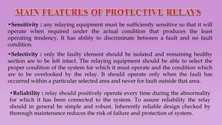
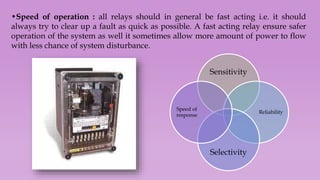
3. Important relay characteristics are sensitivity, selectivity, reliability, and speed of operation. Relays can also be categorized by characteristic, logic, or actuating parameter.
4. Terminology discussed includes pickup level, reset level, operating time, and plug and time setting multipliers which are used to adjust relay settings.


![•Inverse definite minimum time current relay is one in which the operating time is
approximately inversely proportional to the faulty current near pick up value and
becomes substantially constant slightly above the pick up value of the relay[curve
(b)]. This is achieved by using a core of the electromagnet which gets saturated for
current slightly greater than the pick up current.
•Very inverse relay is one in which the saturation of the core occurs at a later stage,
the characteristic assumes the shape as shown in curve (c) and is known as very
inverse characteristic. The time current characteristic is inverse over a greater range
and after saturation tends to definite time.
•Extremely inverse relay is one in which the saturation occurs at a still later stage
than curve (c) in the figure. The equation describing the curve (d) in the figure is
approximately of the form I2t=K, where I is the operating current and t the
operating time.
The time lag in induction type of relays may be achieved by using a permanent
magnet which is so arranged that the relay rotor cuts the flux between the poles of
this magnet. This type of magnet is called Drag Magnet.](https://image.slidesharecdn.com/protectiverelay-240131133459-348ddb01/85/Protective-relay-pptx-22-320.jpg)


