Downloaded 48 times

![l
I
I
J
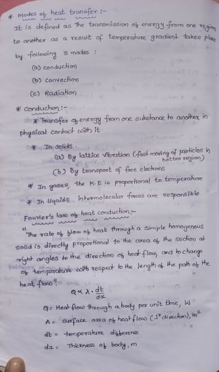
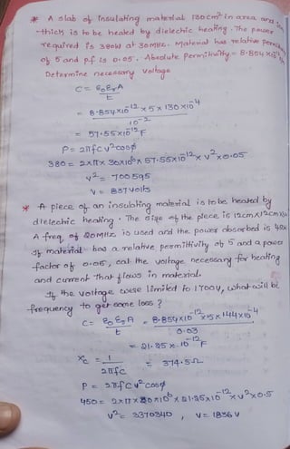
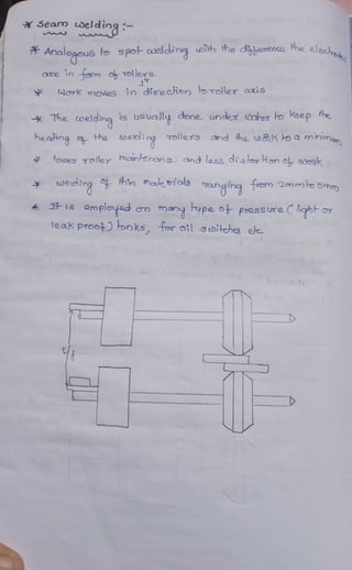
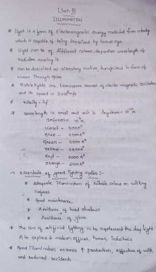
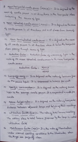
¾ qe~ ~n8 ~
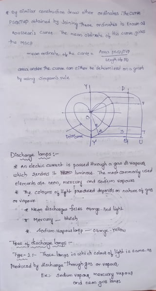
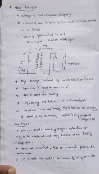
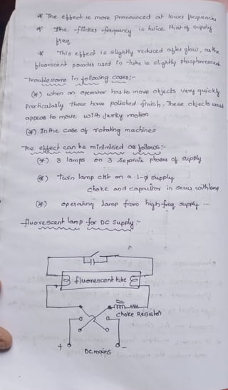
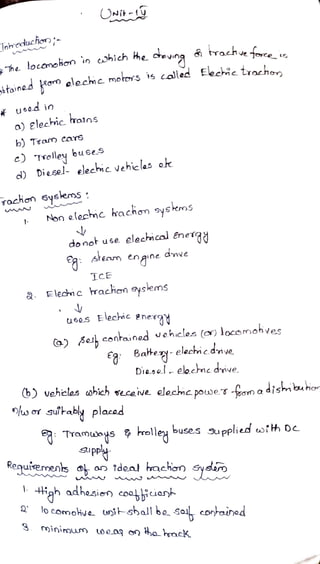
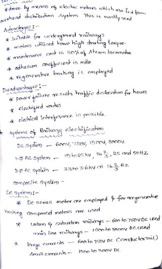
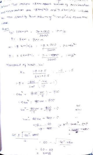
~ ¼hhl)'t -6ys/:iro lo.mps made- ol,- d,bffisi""d 0-~ ,
used t.0hic.h ~N~ near1'd e_qual ilu.ur)rnoJior> .tf) o.JJ
di'lfe.cHo-ns
0~~8 .~ -
~, c ~ ~~ITcJ~6~
.' . .
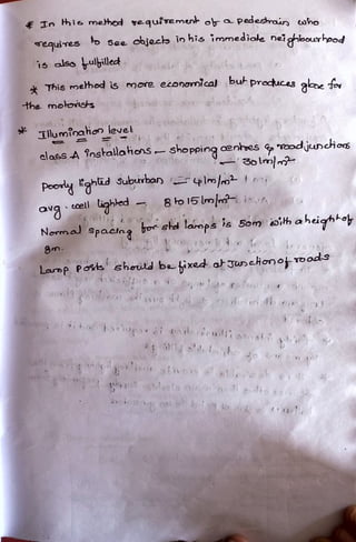
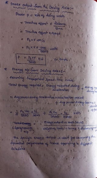
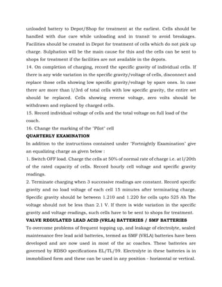
1) p-rovid~ a.de.quati- ~ lluroinQh071
~) ltl)i~ro ~1-,I- dis~bu,~e,ry
'3) avoid
01a.Ye QJ)cf ho:rd -shadcws
., .. : ...Lt) f>rovide.s ti'<thl- ob St/ilnble. cdcx.tv-
•
.·····,~
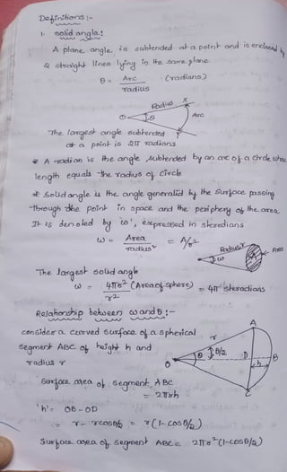
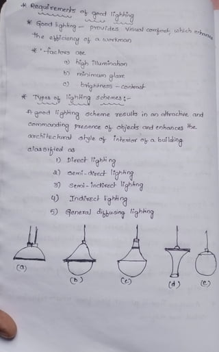
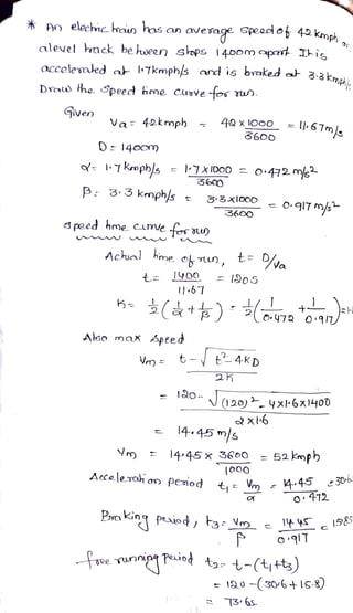
~?--~=--·~ ~ ~06" de.~i8nio51 ~
s ~ - . ~
,, :.tl")kn$r'cJ otr 'fff1.un;naJioY)
$ele.e-Jiem o~ lumfnoJres
6) Gf~e.. Dt"b"bOn')
4) ~W')H'"'r] ~r~'"° ard ~fl=la'"'3 °6- f11)Hi~
5) eooct;~ ~ u~
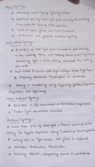
Oj J:')~Ob-~~:-
*""fQ..9uT~e,s p d;'~tre.rl- illuM~r">ctho,')
~()J.ef)6~~ ~ di~enJ- ou~~
(.a.) {ach:,.ie_s- ~ wos~~ps ..::;> 50 - ISoO
Po wez hous~ ~ 100 - aoo
ol,-biciu](https://image.slidesharecdn.com/ueetotalnotes-240217014714-b5c16e47/85/Utilization-of-Electrical-Energy-notes-pdf-95-320.jpg)
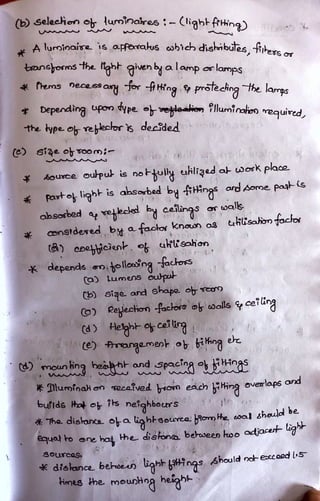
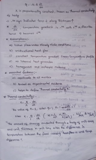
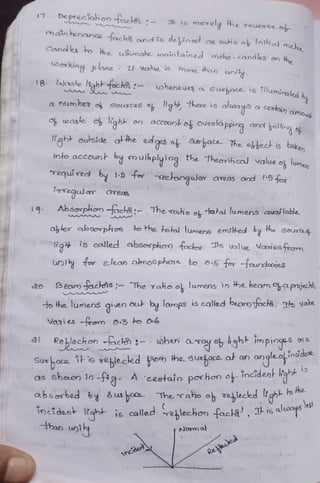
![s~~-!:}it:]:-
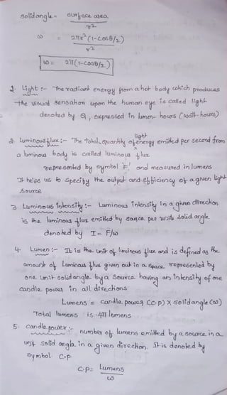
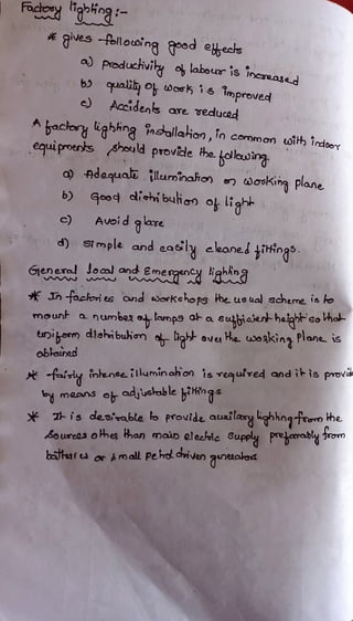
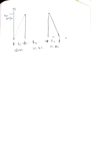
o~~"~ :-
~
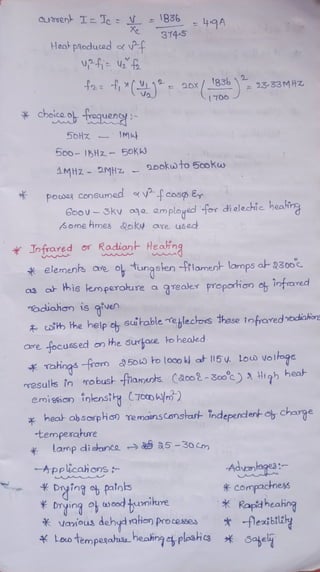
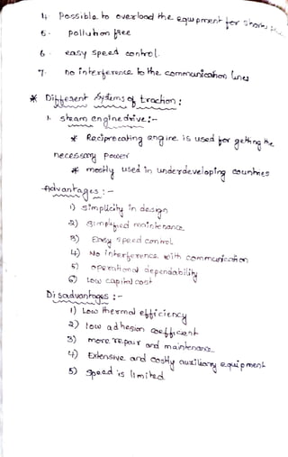
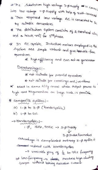
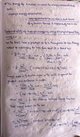
{!J co.o:z,-~ Jis,,L 0~nuc.ka')5 on y~ 1r-,a,d~ ~
-o)J~ ~~ OJ"'ld c00v~ni~ ,
@ enho.n~I+~ cot'l'ln'W1 i1 valuct. o}r.skeJ-
© rn'"1?. olhoclive..
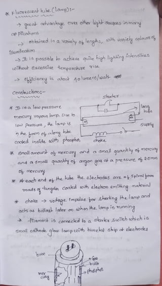
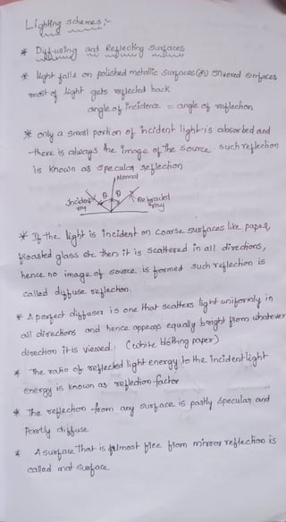
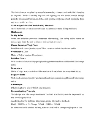
~ p,rfnciple..s f"vot"ed : -
t • 0,nt,-us~crr>
a. . /4pe.cul~ 'l"e.~ledio-o
~ : -
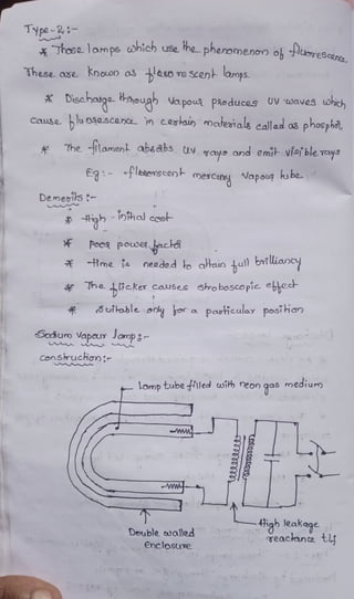
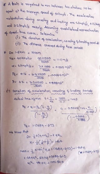
* lhe. lo.~p.!> ~H-e-d (J)jH) sull--a.bte. 'lfel,-e.~~ ~e.
'¾
I
I
ernplo~d ,the- des,ca.., ot,- 14)e. ve&,le.c."°"..s is. soc.h H-xd- H-ey
"Q dT~ I-he tiijhl- dotbn/Jlo,1'4s and sp-reo4 ~ uni!,mm~
cu p~asthl~ ttvex .h-Ubo-OLol,- rrocc4
.:f Ih o-fd.eJ h, a'-'~id ala-re · H->e. ~eh-lee~°"~ modei..,
~e ~o.-04-S°
* tJie ~tr~ao p~'"" o-n Ho)~ CftJl~fnc.ide.n~ SUJi~01J
"1"lalCU thL --a,ocl b~t~_
l-o o~"~ .
~~c.olcr.J~nca ~llw-r,ir,oh~ por~1-opei,.,~ ~ fn"e-rse
s9u01t"e lo.t&l me.l+,cx:t ·,.ei emplor · .
~ ..-e.sullonl- 'rllurw,To~at) te ~e.. ,SUll) ~,-.~ ilh.1Mt~ ~
dua. ~ Q..OV') ICIN'lp.
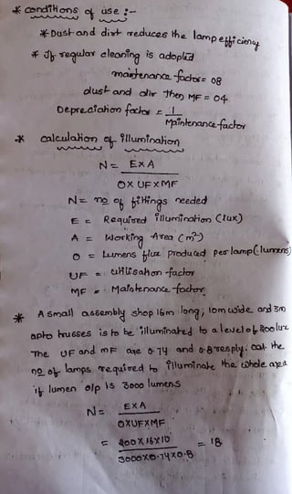
Cop Q..CO.}~ ~~~c:H :-,
~ --.,, ......,
* ~e.t,-ie..c.h:,is o.Te. c.u,rve..cl u f'W~Tes /4~ ~l+it- lif
; 5 H1'Y'otu0 c,f) Yo~ ~ a. ~e.,t J°(1e,~e.0 ~i,..,dcfeJU-](https://image.slidesharecdn.com/ueetotalnotes-240217014714-b5c16e47/85/Utilization-of-Electrical-Energy-notes-pdf-101-320.jpg)
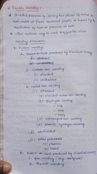
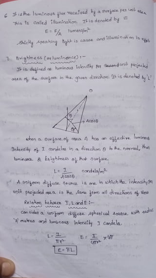
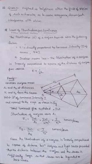
![ooley Me-loco e-l lG Hl] Ls'+s]
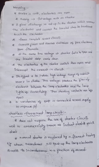
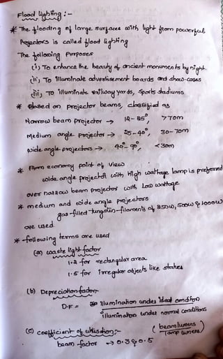
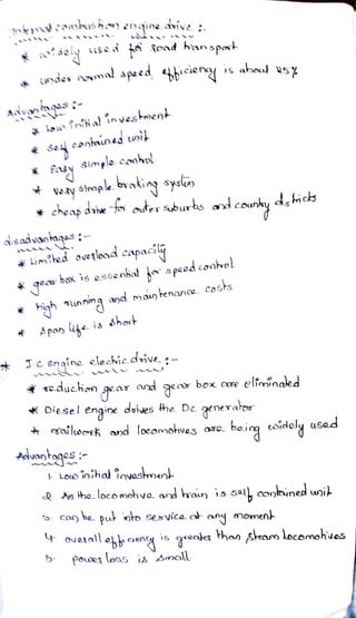
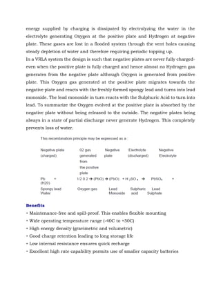
3600
he
usl atu a3600
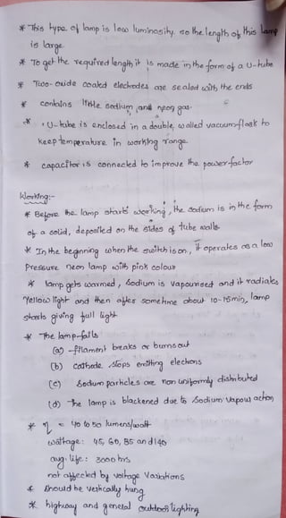
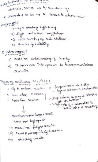
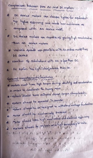
Speciie enexgy oupo
Enegy oukpu- or he munin wal-hours
y etobhoftraip in omes dishard.ouiok
o-ol 6727o +0-778l981WG+r)S
l
WxS
olo72vxa oTR SL(81 4T
lh pesreorne-kn
She soackislevel ene GEo
6pari eneia ostmprio
Colo2V7He o218x h/enne.b](https://image.slidesharecdn.com/ueetotalnotes-240217014714-b5c16e47/85/Utilization-of-Electrical-Energy-notes-pdf-133-320.jpg)
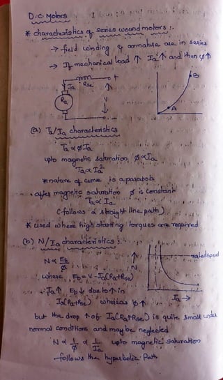
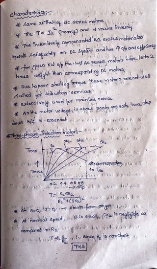
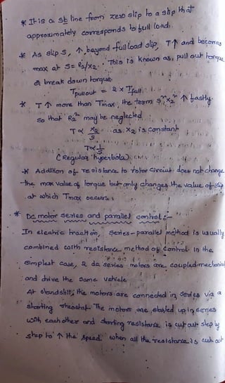
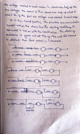
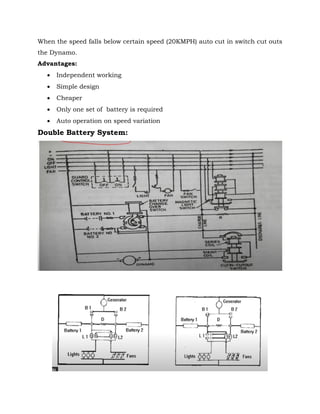

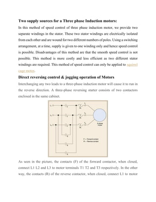
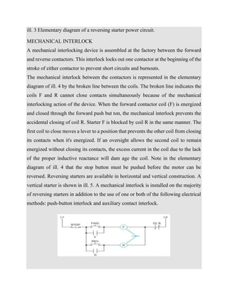
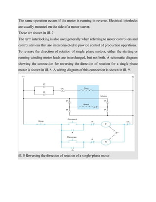
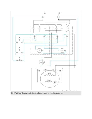
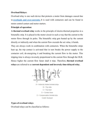
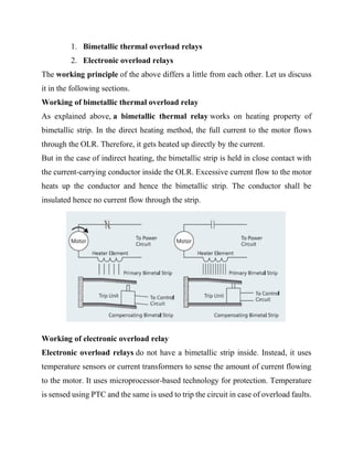
This document discusses several topics related to three-phase induction motors and their speed and direction control. It describes two methods for speed control using separate stator windings, and also discusses direct reversing and jogging control by interchanging motor leads. Interlocking methods like mechanical, push-button, and auxiliary contact interlocks are covered for reversing motor starters. Overload relays, their types and uses are also summarized. Finally, the document discusses contactor control circuits and their operation using start and stop pushbuttons.


