

![ NLX (Supports motherboards with overall
dimensions of 9.0" x 13.6" [maximum] to 8.0" x 10.0"
[minimum]) Implemented in 1998 by Intel this form
factor is gaining popularity the last couple of years
because there found on most clone computers
Support for the Pentium II
Support for AGP
Support for USB.
Support for DIMM.
Easier Access to internal components
Support for motherboards that can be removed
without using tools](https://image.slidesharecdn.com/presentation1motherboard-120519025410-phpapp01/75/P-C-motherboard-14-2048.jpg)
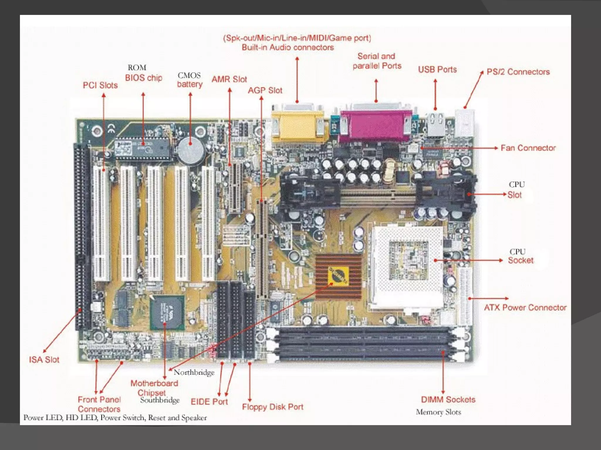
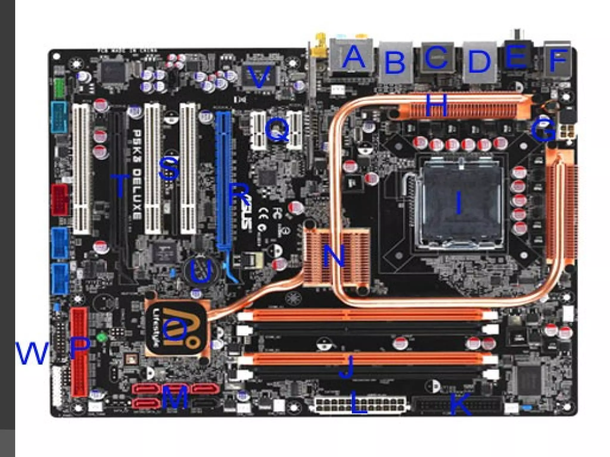
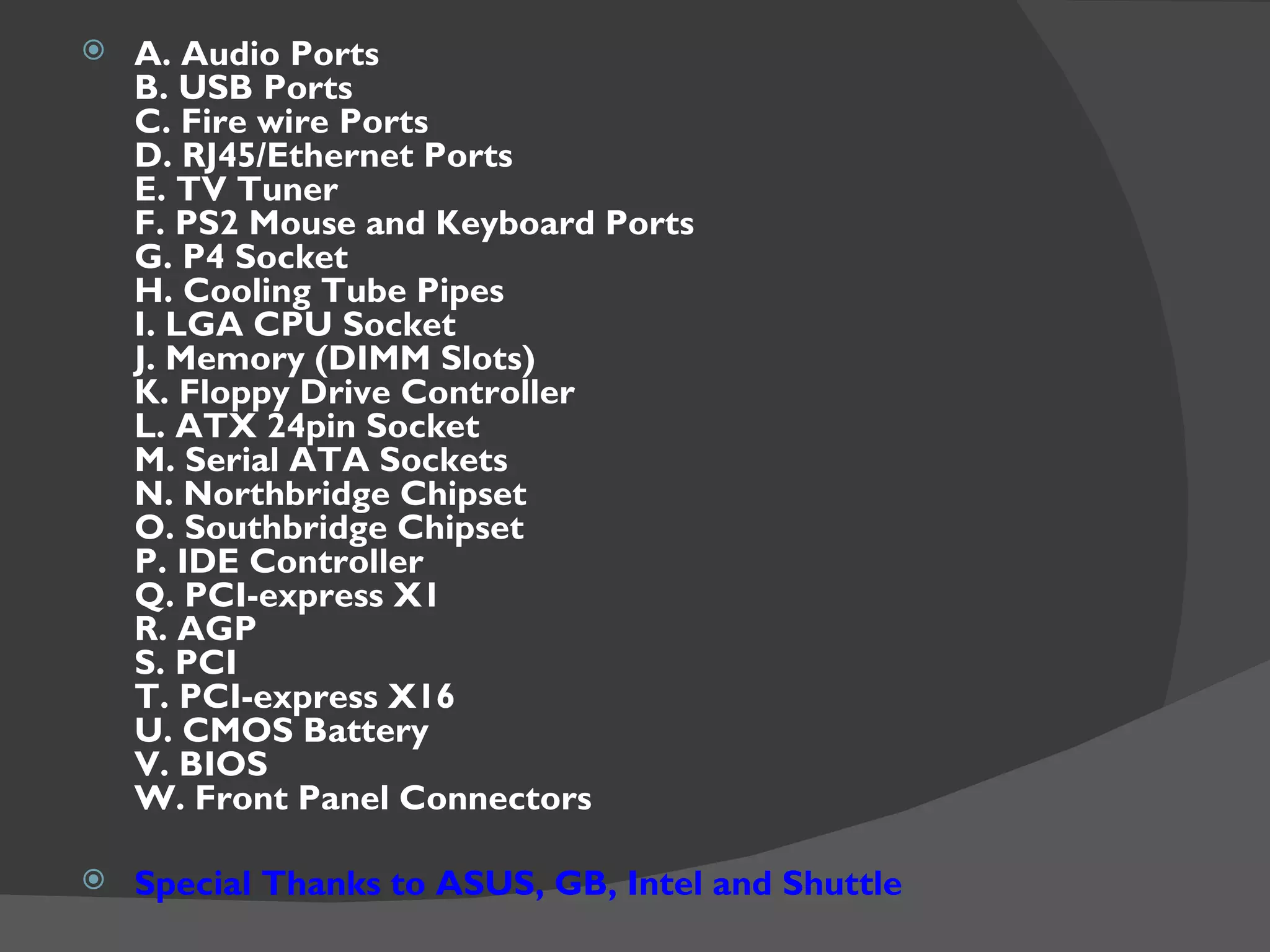
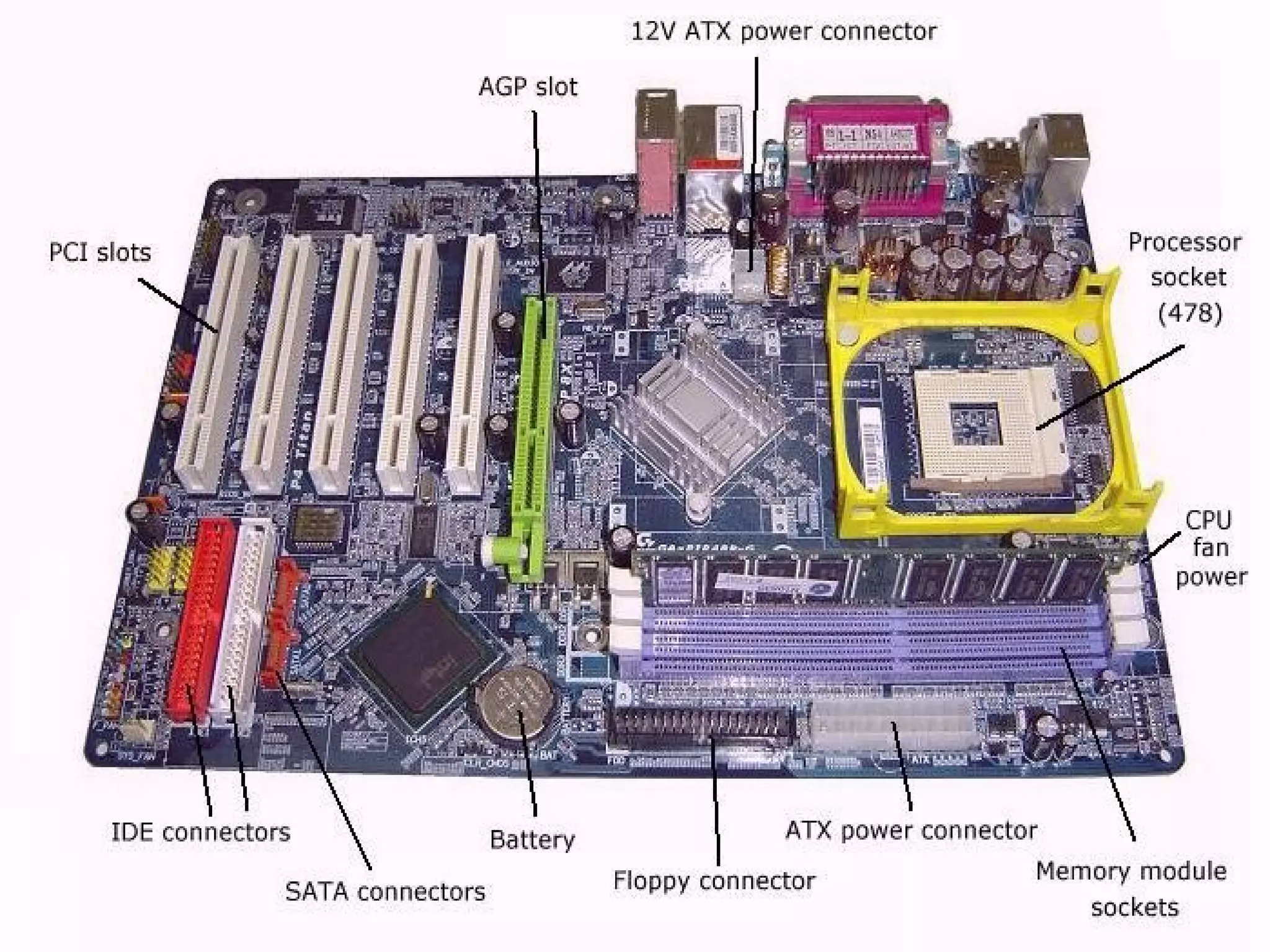
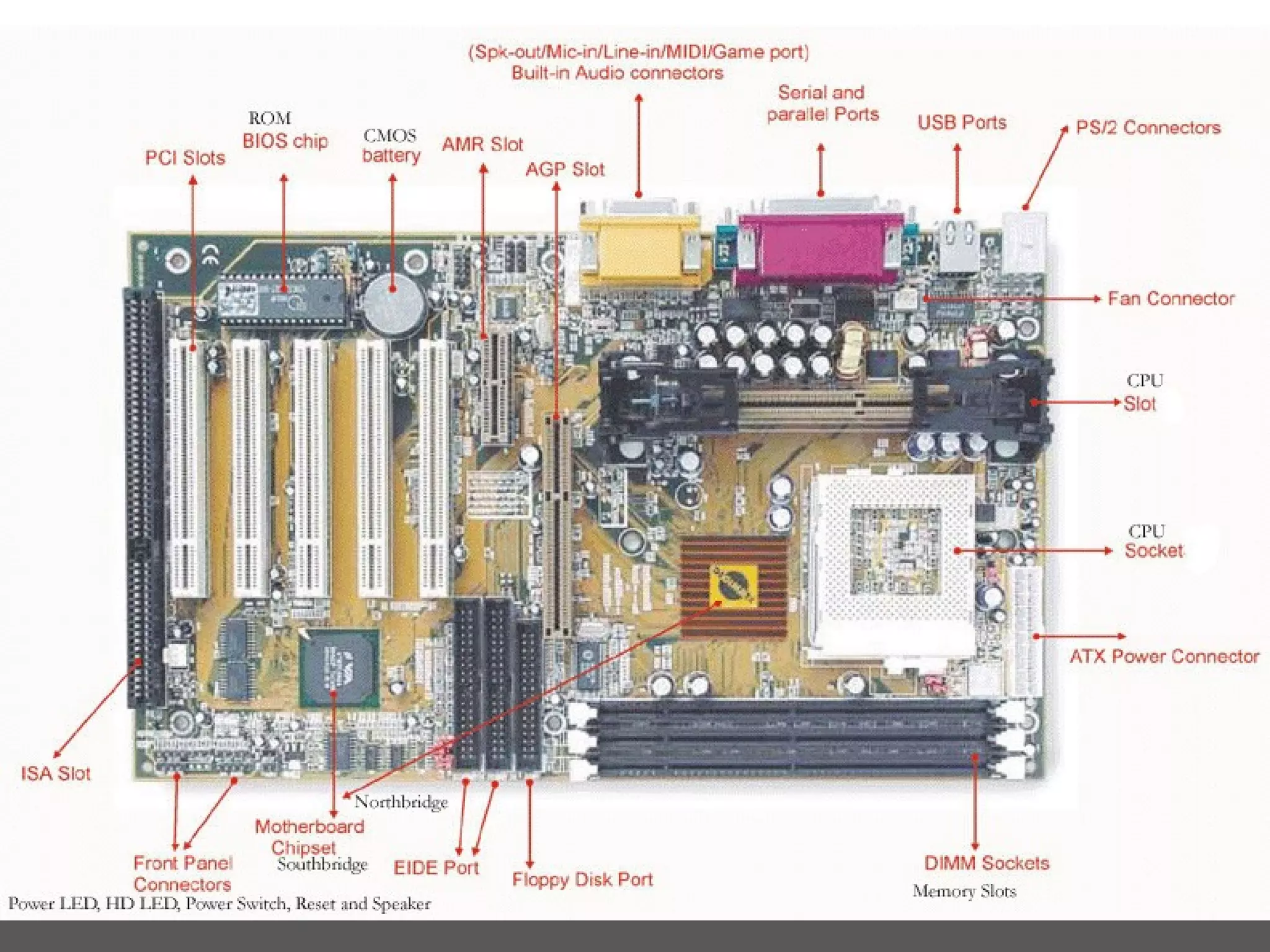

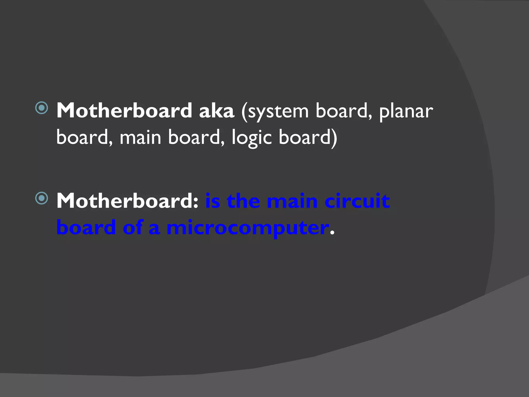
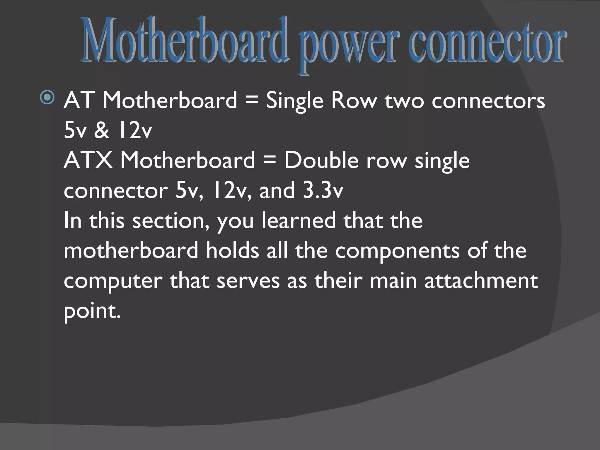
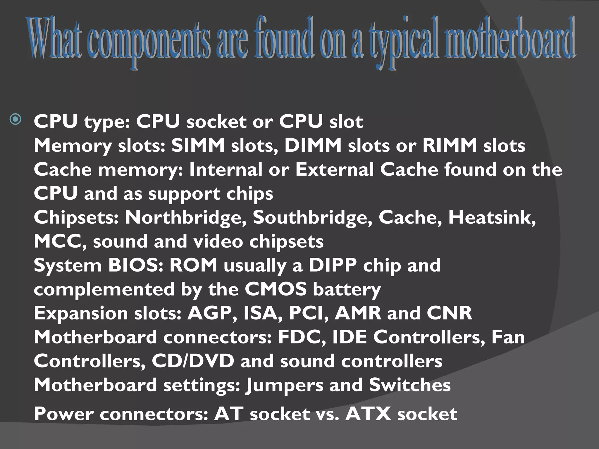
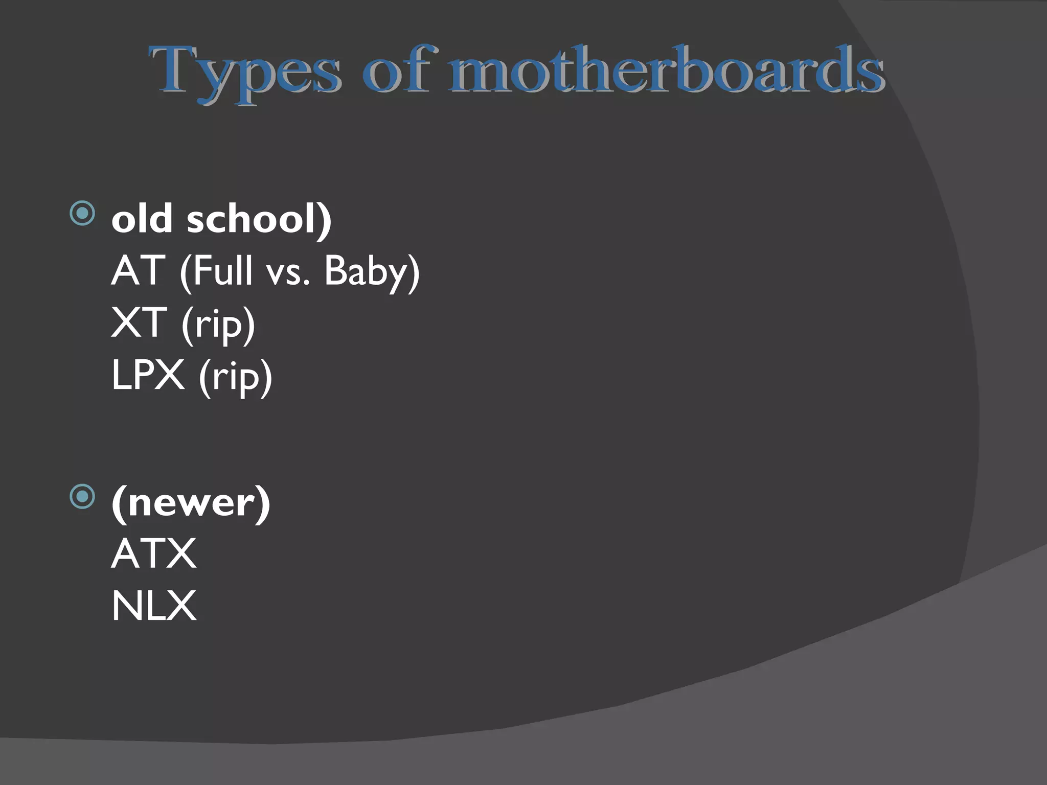
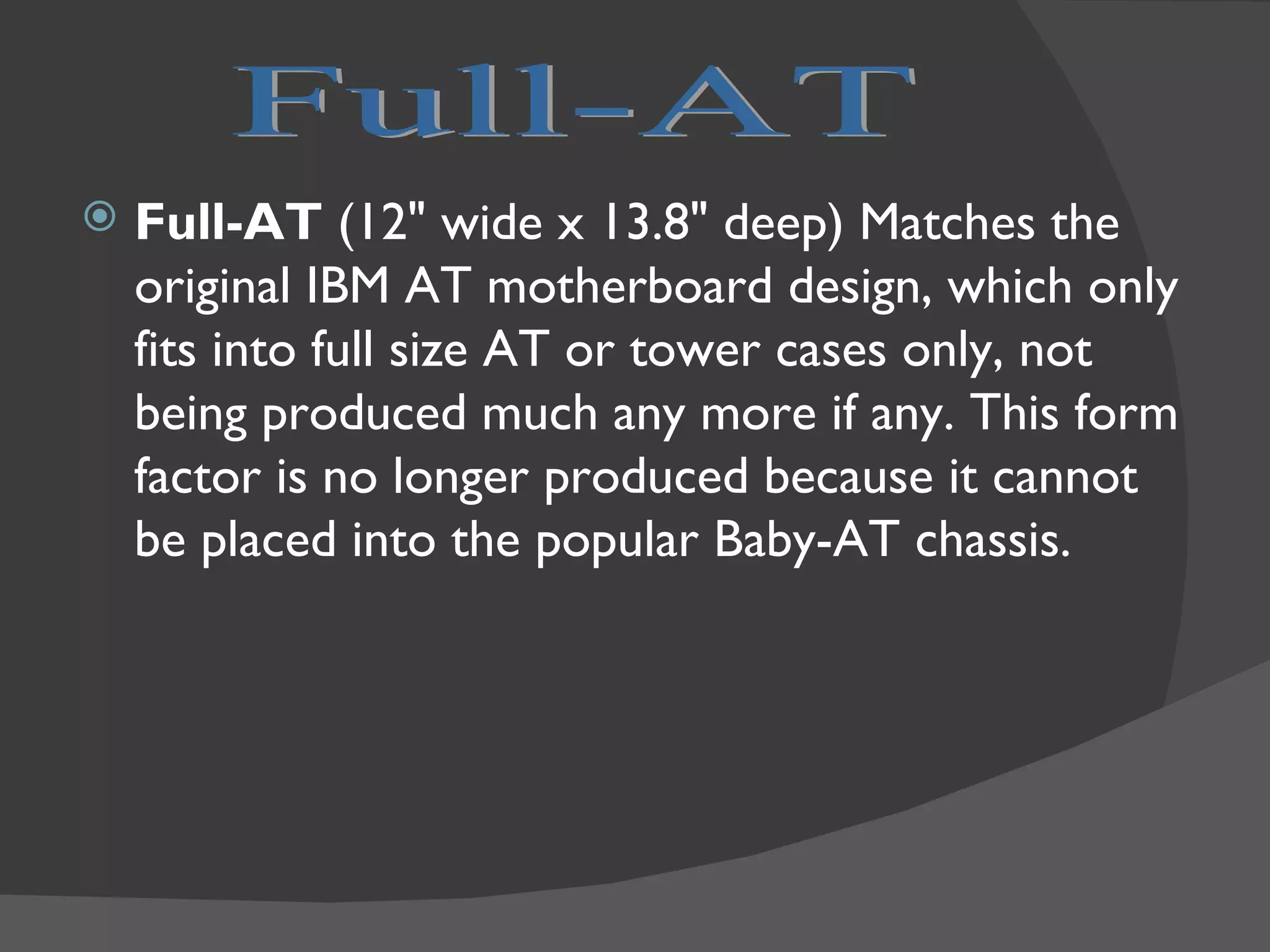
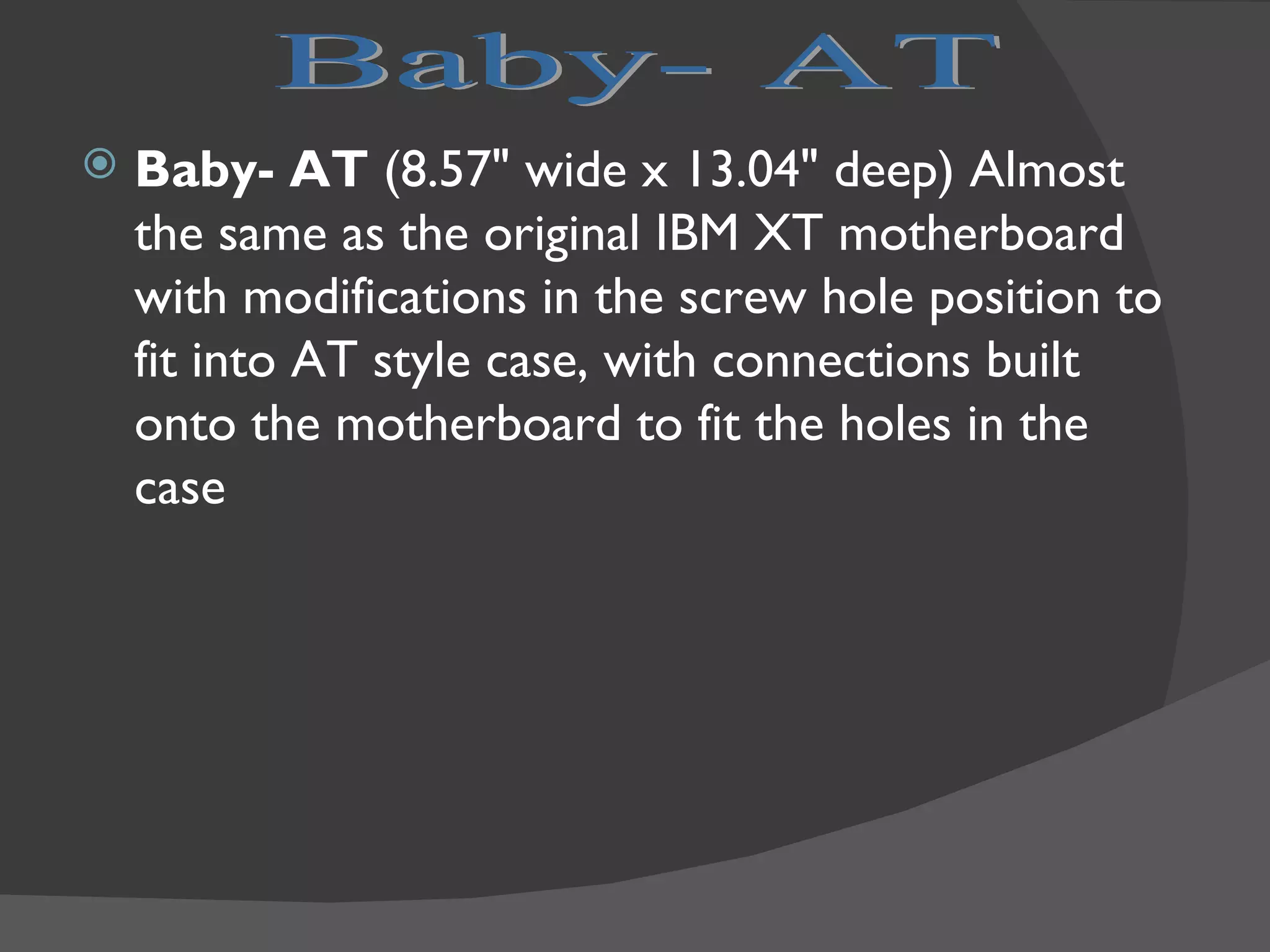
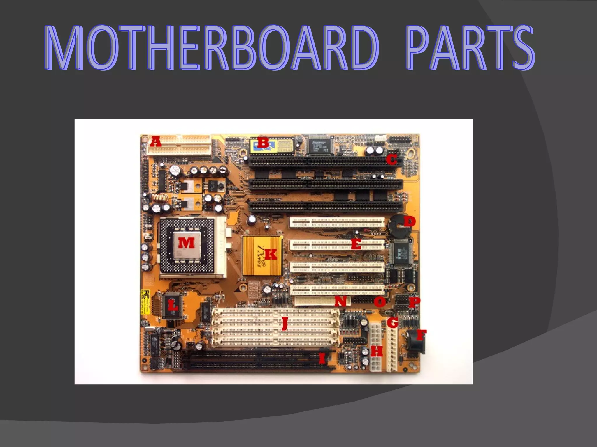
The document provides information about different types of motherboards including AT, ATX, and NLX motherboards. It discusses the key components and features of motherboards such as the CPU socket, memory slots, expansion slots, and power connectors. The steps for building a PC from individual components are outlined, with an emphasis on proper electrostatic discharge prevention procedures when handling components.


![Developing the Coaching Skills of Your Managers and Leaders [Webinar 04.13.16]](https://cdn.slidesharecdn.com/ss_thumbnails/coachingskills041316slides-160413135753-thumbnail.jpg?width=640&height=640&fit=bounds)


![Coded Agents – with UiPath SDK + LangGraph [Virtual Hands-on Workshop]](https://cdn.slidesharecdn.com/ss_thumbnails/codedagentsdeck-251215155422-5497c599-thumbnail.jpg?width=640&height=640&fit=bounds)


