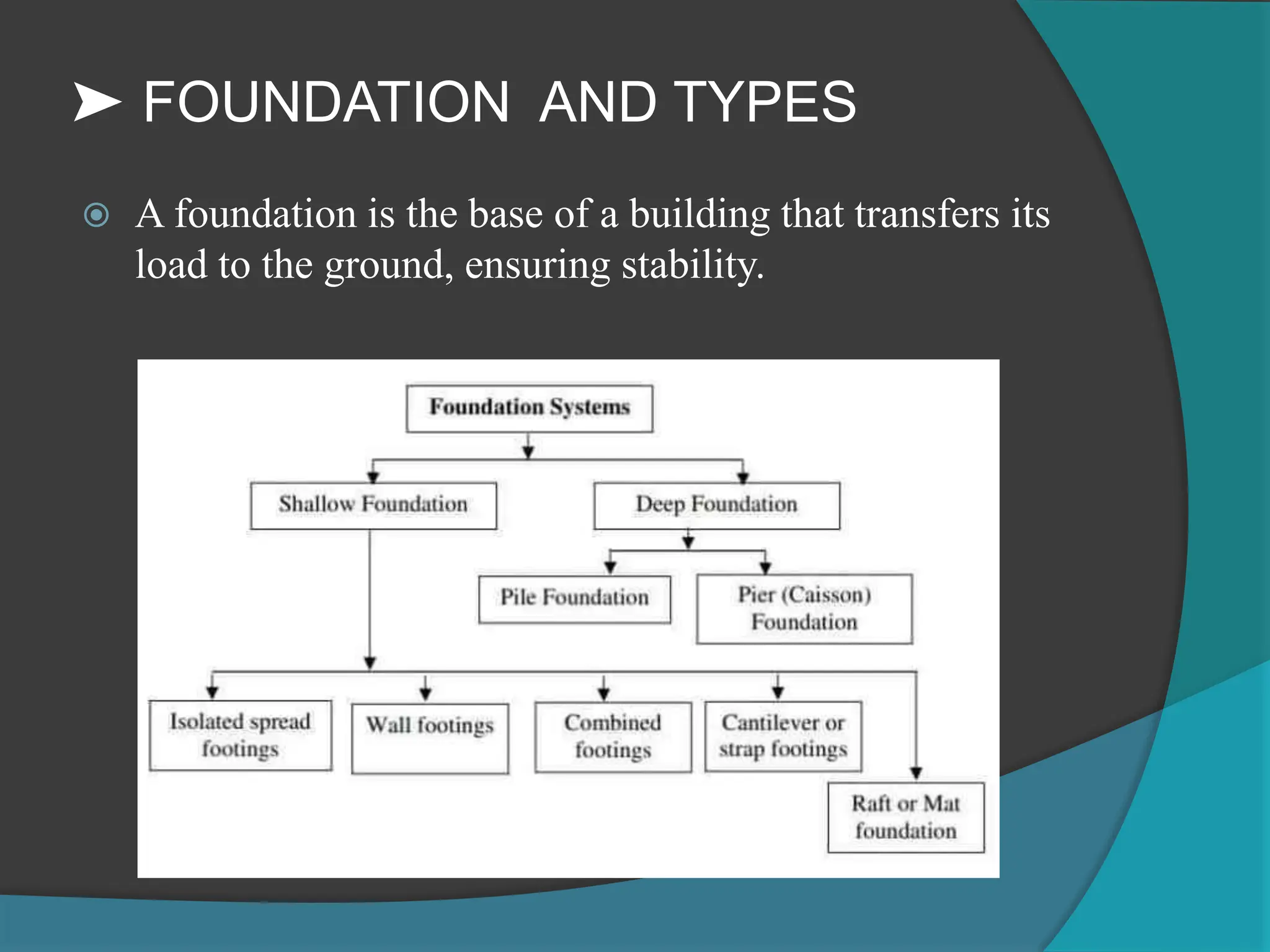
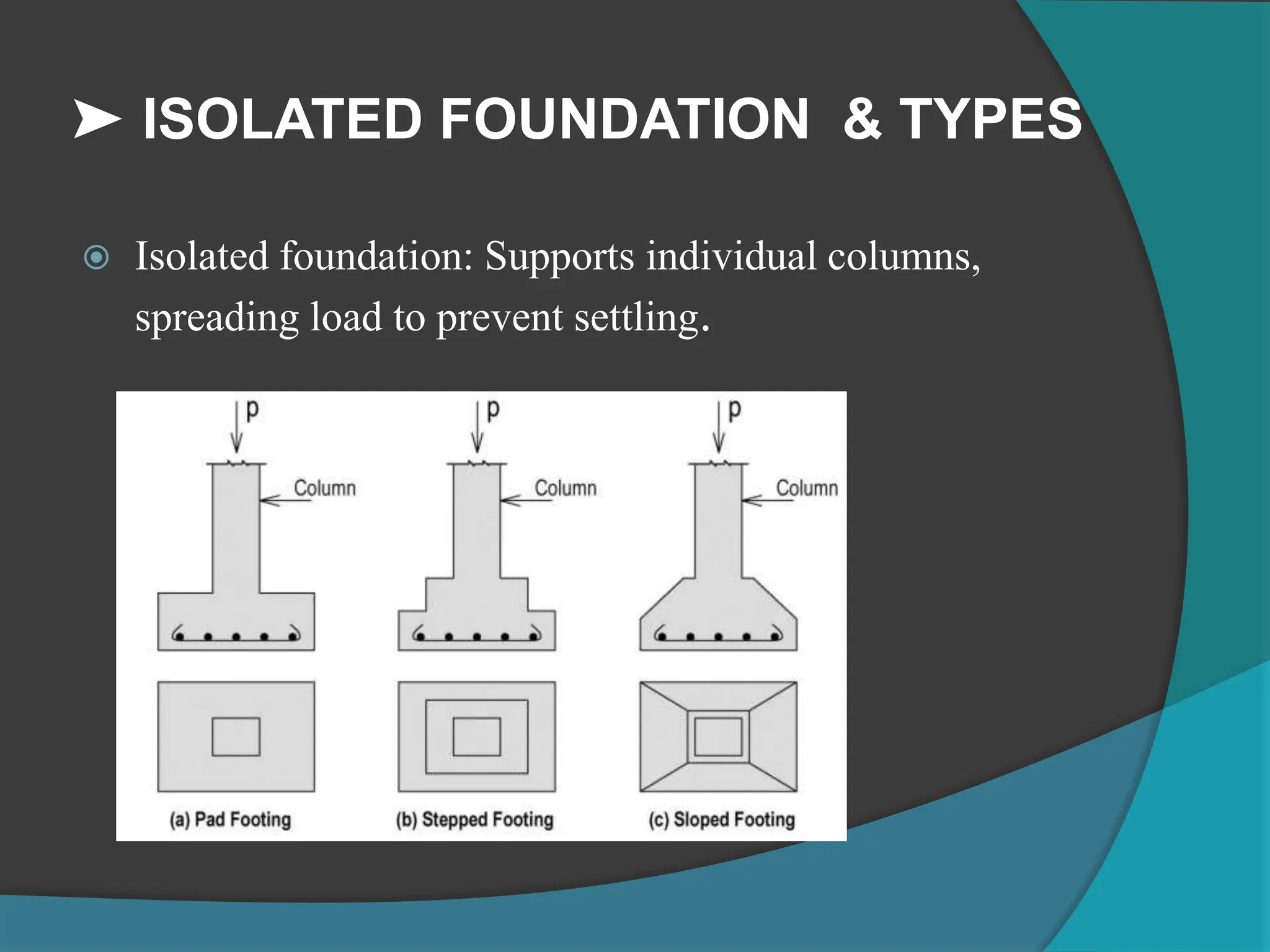
Presented by :
Sondarva shiva
➤ FOUNDATION AND TYPES
 A foundation is the base of a building that transfers its
load to the ground, ensuring stability.
➤ ISOLATED FOUNDATION & TYPES
 Isolated foundation: Supports individual columns,
spreading load to prevent settling.
➤ The Structural design of the footing
includes the design of…
 Depth of footing
 Reinforcement requirement
 Check on serviceability
➤ Mechanism of load transfer
➤ Design Considerations:
 Minimum reinforcement: (As per IS456:2000, clause
26.5.2.1&2
 ➤ The mild steel reinforcement in either direction in
slabs shall not be less than 0.15 percent of the total
cross sectional area. However, this value can be reduced
to 0.12 percent when high strength deformed bars or
welded wire fabric are used
 ➤ The diameter of reinforcing bars shall not exceed
one eight of the total thickness of the slab.
➤ Design Considerations:
 Spacing of reinforcement
 Minimum Spacing: The clear distance between bars
should not be less than the bar diameter or 5 mm more
than the maximum size of the coarse aggregate.
 Maximum Spacing: The spacing should not exceed
three times the effective depth of the footing or 300
mm, whichever is smaller.
➤ Design Considerations:
 ➤ The Minimum thickness of edge of the footing on
the soil and rock should be 150mm and that on top of
piles should not be less than 300mm.
 ➤The column transfers the load to top of footing by
bearing. In limit state design, the value of pressure
allowed under direct compression on an reinforced
loaded area of same size is to be limited to 0.45fck as
given by IS 456: clause 33.4.
 ➤Development length according to IS, the depth
required for anchorage is given by,
➤Development length
 According to IS, the depth required for anchorage is
given by,
➤ SHEAR
1. One way shear (Wide beam Shear):
 One way shear is similar to Bending shear in slabs
considering the footing as a wide beam. Shear is taken
along the vertical plane extending the full width of the
base
 Lowest value of allowable shear in Table 13 of IS
456:2000 Is 0.35N/mm² is recommended.
 In one way shear, the shear force to be resisted is the sum
of the upward forces in the foundation area from the
critical section to the edge of the footing.
 The shear per unit area is given by
 Tc = v/bd
 This is tv should not be more than τc specified.
 2. Two way shear (Punching Shear):
 ➤This is indicates the tendency of column to punch
through the footing slab. This type shear also occurs
around the flat slab around the supporting column.
 ➤According to the IS456, punching shear has to be
checked along the surface of the truncated cone around
the column load. Called critical perimeter which should be
at a distance of d/2 from the column face.
 ➤The maximum value of shear stress in LSM according
to IS456 clause 30.6.3.1 is taken as 0.25√fck
3. Bending Moment for Design
Consider the entire footing as
cantilever beam from the face of
The column and calculate the BM
Calculate span for the cantilever
portion (Hashed portion)
= PL x L/2 = (P*L^2)/2
Substitute I= [(B - D )/2 ]
M xx =P( B-D/2 )^2x1/2
This is BM for 1m width of the
beam
DESIGN STEPS :
Size of footing :
 Assume the weight of footing – 5-10% working load on column
 Ultimate bearing capacity of soil = 2*SBC
 Factored load = 1.5*working load on footing
 Area of footing : Af = factored load
ultimate load bearing capacity
Upward soil pressure :
upward soil pressure = factored load on column
area of footing
Depth of footing :
 Find depth required for shear for one way shear criteria
 Find depth required for shear for Two way shear criteria
 Find Bending moment at critical section and depth
required for Bending moment.
 The depth of footing is maximum of above three values.
 Find area of steel & no. of bars to be provided
Reinforcement details:
Devlopment length

Design of isolated foundation types of isolated foundation

  • 1.
  • 2.
    ➤ FOUNDATION ANDTYPES  A foundation is the base of a building that transfers its load to the ground, ensuring stability.
  • 3.
    ➤ ISOLATED FOUNDATION& TYPES  Isolated foundation: Supports individual columns, spreading load to prevent settling.
  • 4.
    ➤ The Structuraldesign of the footing includes the design of…  Depth of footing  Reinforcement requirement  Check on serviceability
  • 5.
    ➤ Mechanism ofload transfer
  • 6.
    ➤ Design Considerations: Minimum reinforcement: (As per IS456:2000, clause 26.5.2.1&2  ➤ The mild steel reinforcement in either direction in slabs shall not be less than 0.15 percent of the total cross sectional area. However, this value can be reduced to 0.12 percent when high strength deformed bars or welded wire fabric are used  ➤ The diameter of reinforcing bars shall not exceed one eight of the total thickness of the slab.
  • 7.
    ➤ Design Considerations: Spacing of reinforcement  Minimum Spacing: The clear distance between bars should not be less than the bar diameter or 5 mm more than the maximum size of the coarse aggregate.  Maximum Spacing: The spacing should not exceed three times the effective depth of the footing or 300 mm, whichever is smaller.
  • 8.
    ➤ Design Considerations: ➤ The Minimum thickness of edge of the footing on the soil and rock should be 150mm and that on top of piles should not be less than 300mm.  ➤The column transfers the load to top of footing by bearing. In limit state design, the value of pressure allowed under direct compression on an reinforced loaded area of same size is to be limited to 0.45fck as given by IS 456: clause 33.4.  ➤Development length according to IS, the depth required for anchorage is given by,
  • 9.
    ➤Development length  Accordingto IS, the depth required for anchorage is given by,
  • 10.
    ➤ SHEAR 1. Oneway shear (Wide beam Shear):  One way shear is similar to Bending shear in slabs considering the footing as a wide beam. Shear is taken along the vertical plane extending the full width of the base  Lowest value of allowable shear in Table 13 of IS 456:2000 Is 0.35N/mm² is recommended.  In one way shear, the shear force to be resisted is the sum of the upward forces in the foundation area from the critical section to the edge of the footing.  The shear per unit area is given by  Tc = v/bd  This is tv should not be more than τc specified.
  • 11.
     2. Twoway shear (Punching Shear):  ➤This is indicates the tendency of column to punch through the footing slab. This type shear also occurs around the flat slab around the supporting column.  ➤According to the IS456, punching shear has to be checked along the surface of the truncated cone around the column load. Called critical perimeter which should be at a distance of d/2 from the column face.  ➤The maximum value of shear stress in LSM according to IS456 clause 30.6.3.1 is taken as 0.25√fck
  • 13.
    3. Bending Momentfor Design Consider the entire footing as cantilever beam from the face of The column and calculate the BM Calculate span for the cantilever portion (Hashed portion) = PL x L/2 = (P*L^2)/2 Substitute I= [(B - D )/2 ] M xx =P( B-D/2 )^2x1/2 This is BM for 1m width of the beam
  • 14.
    DESIGN STEPS : Sizeof footing :  Assume the weight of footing – 5-10% working load on column  Ultimate bearing capacity of soil = 2*SBC  Factored load = 1.5*working load on footing  Area of footing : Af = factored load ultimate load bearing capacity Upward soil pressure : upward soil pressure = factored load on column area of footing
  • 15.
    Depth of footing:  Find depth required for shear for one way shear criteria  Find depth required for shear for Two way shear criteria  Find Bending moment at critical section and depth required for Bending moment.  The depth of footing is maximum of above three values.  Find area of steel & no. of bars to be provided
  • 16.