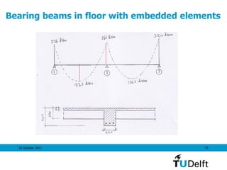
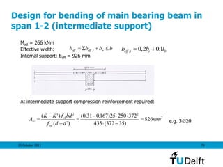
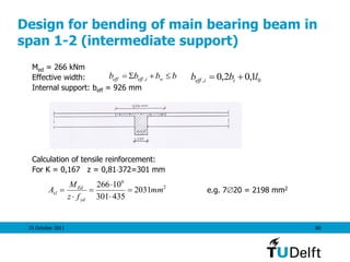
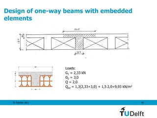
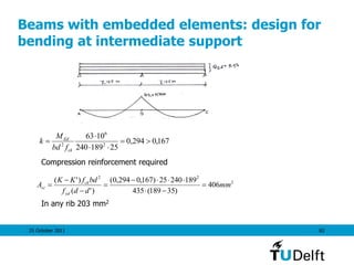
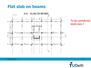
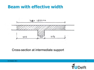
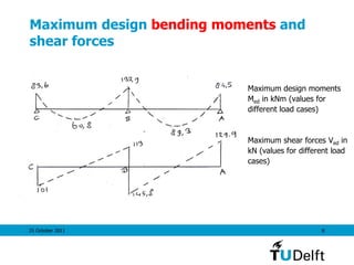
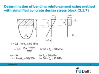
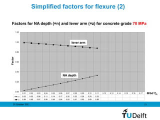
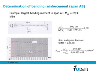
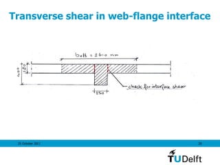
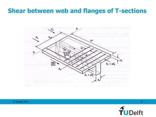
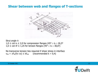
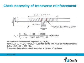
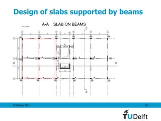
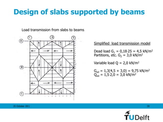
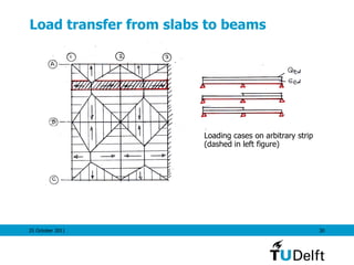
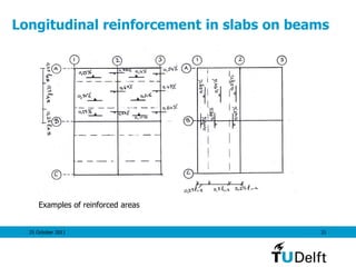
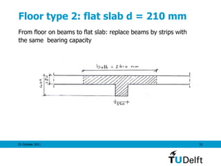
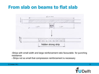
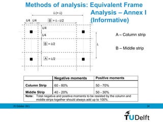
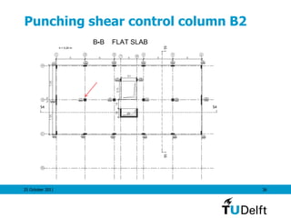
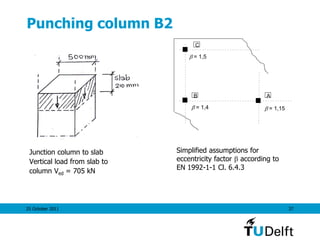
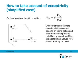
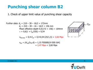
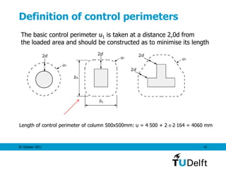
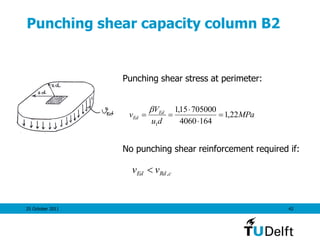
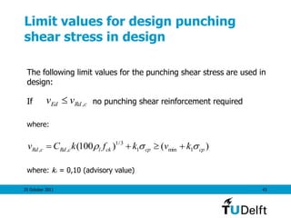
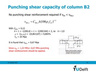
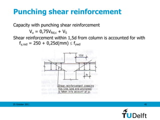
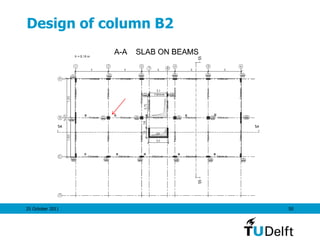
The document discusses the design of flat slabs and beams. It provides examples of determining the effective width of beams supported by slabs, calculating bending reinforcement, checking shear capacity, and designing transverse reinforcement. Methods for load transfer from slabs to beams are presented. The document also examines punching shear control at a column, providing simplified assumptions for the eccentricity factor and checking the upper limit value for design punching shear stress.


![25 October 2011 39
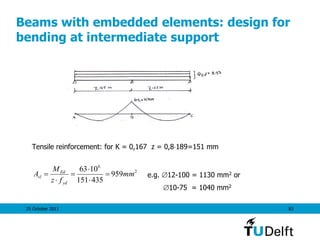
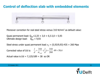
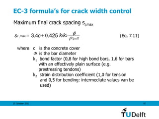
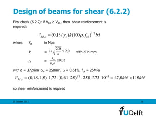
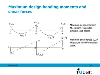
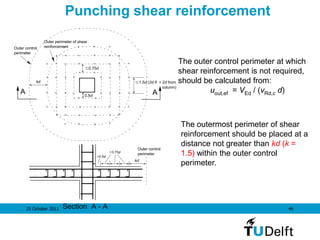
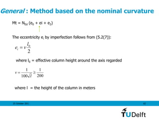
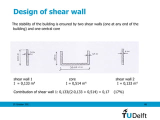
Upper limit value for design punching
shear stress in design
cdRd
Ed
Ed fv
du
V
v
4,0max,
0
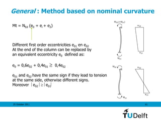
At the perimeter of the loaded area the maximum punching shear
stress should satisfy the following criterion:
where:
u0 = perimeter of loaded area
= 0,6[1 – fck/250]](https://image.slidesharecdn.com/04ec2wswalravenulssls-150619063116-lva1-app6891/85/04-ec2-ws_walraven_ulssls-39-320.jpg)


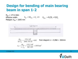
![25 October 2011 55
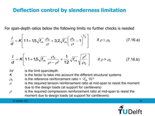
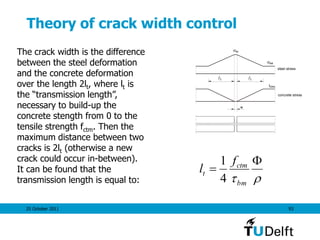
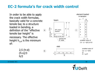
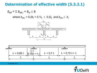
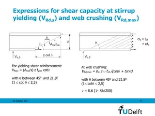
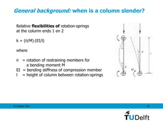
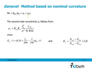
General background: determination of effective
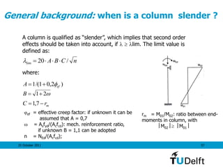
column length (1) (5.8, 5.8.3.2)
Failing
column
Non failing
column
End 1
End 2
Non failing
columnSimplifying assumption:
* The contribution of the adjacent “non
failing ” columns to the spring stiffness is
ignored (if this contributes in a positive
sense to the restraint)
* for beams for /M the value l/2EI may
be assumed (taking account of loss of
beam stiffness due to cracking)
Assuming that the beams are symmetric with regard to the column and that their
dimensions are the same for the two stories, the following relations are found:
k1 = k2 = [EI/l]column / [SEI/l]beams = [EI/l]column / [22EI/l]beams = 0,25
where: = [EI/l]column / [EI/l]beams](https://image.slidesharecdn.com/04ec2wswalravenulssls-150619063116-lva1-app6891/85/04-ec2-ws_walraven_ulssls-55-320.jpg)
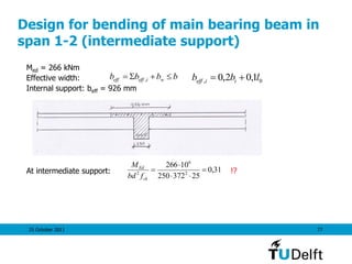
![25 October 2011 59
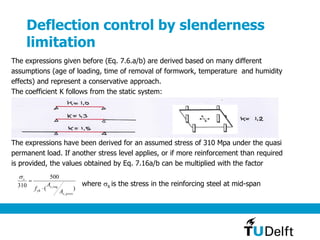
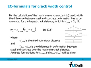
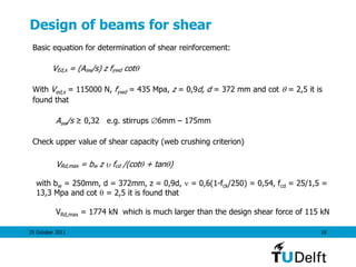
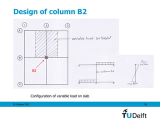
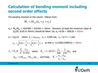
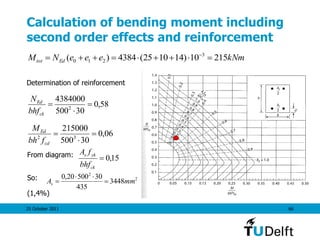
Determination of columns slenderness
First step: determination of rotational spring stiffness at end of column:
Column: EI/l = 0,043106 kNm2
Beam: EI/l = 0,052106 kNm2
K1 = [EI/l]col/[SEI]beams = 0,043/(20,052) = 0,41
If the beam would be cracked a value of 1,5 k1 would be more realistic. This would result
in l0 = 0,80l = 3,2m.
ll
k
k
k
k
ll 70,0)
02,1
41,0
1(5,0)
45,0
1)(
45,0
1(5,0 2
2
2
1
1
0
](https://image.slidesharecdn.com/04ec2wswalravenulssls-150619063116-lva1-app6891/85/04-ec2-ws_walraven_ulssls-59-320.jpg)
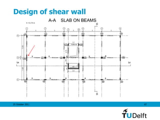
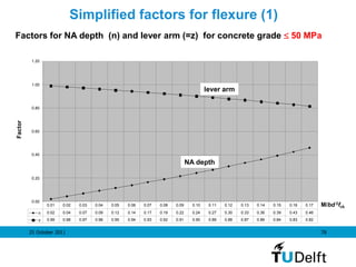
![25 October 2011 69
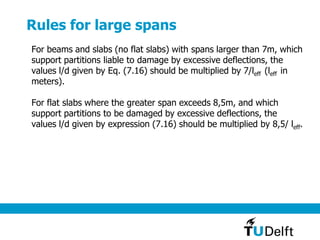
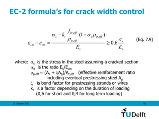
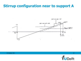
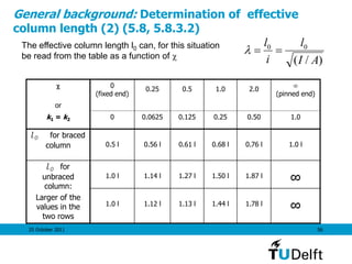
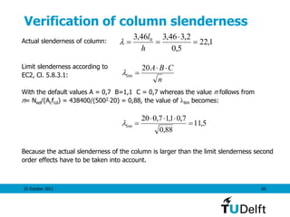
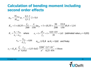
Second order effects to be regarded?
“If second order effects are smaller than 10% of the first
order moments they can be neglected”.
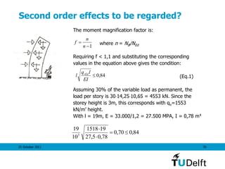
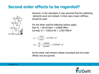
Moment magnification factor:
]
1/
1[0
EdB
EdEd
NN
MM
2
2
)12,1( l
EI
NB
lqN vEd
NB is the buckling load of the system sketched, l = height of building, qv =
uniformely distributed load in vertical direction, contributing to 2nd order
deformation.
qv](https://image.slidesharecdn.com/04ec2wswalravenulssls-150619063116-lva1-app6891/85/04-ec2-ws_walraven_ulssls-69-320.jpg)