
Downloaded 329 times


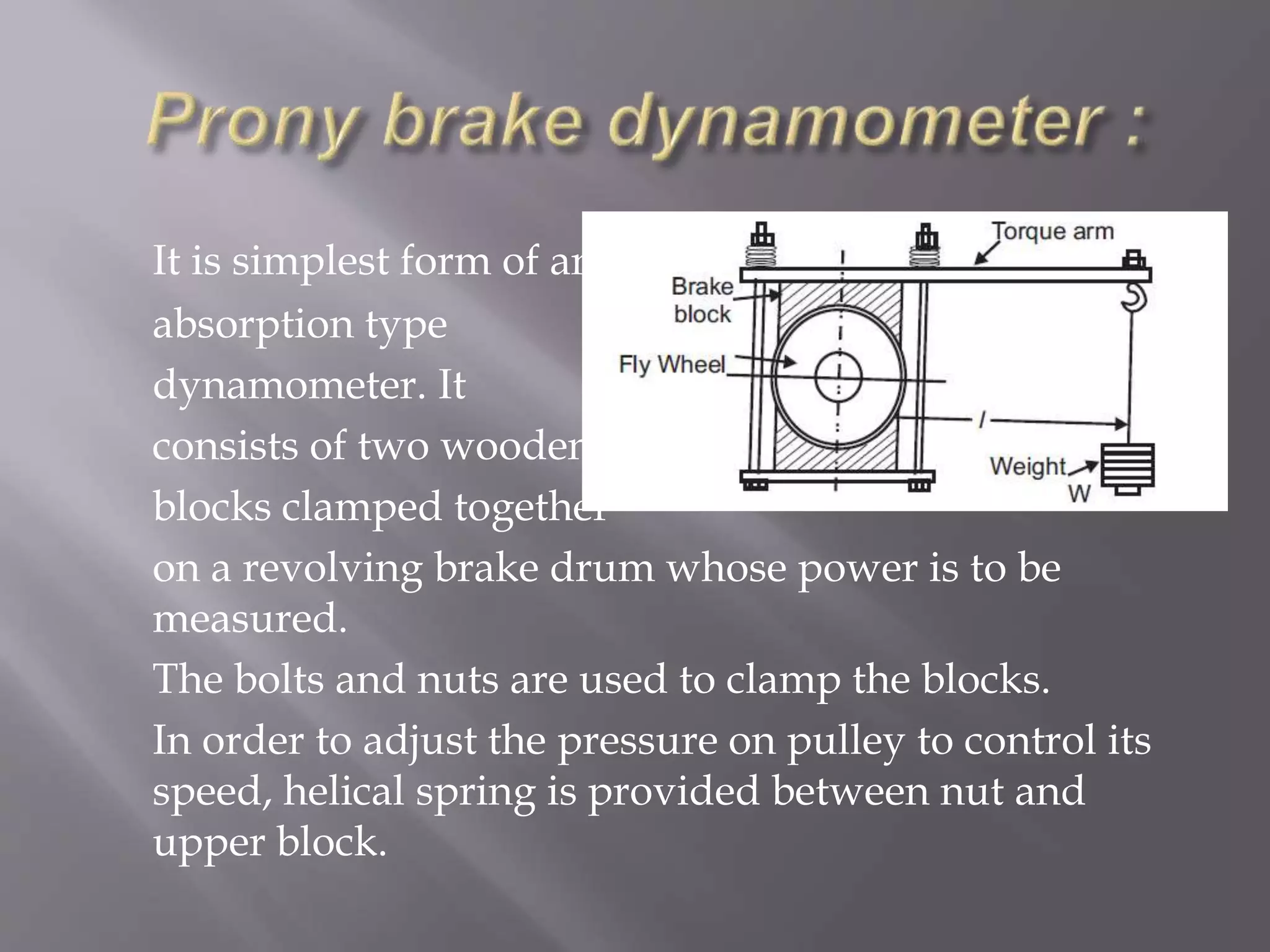


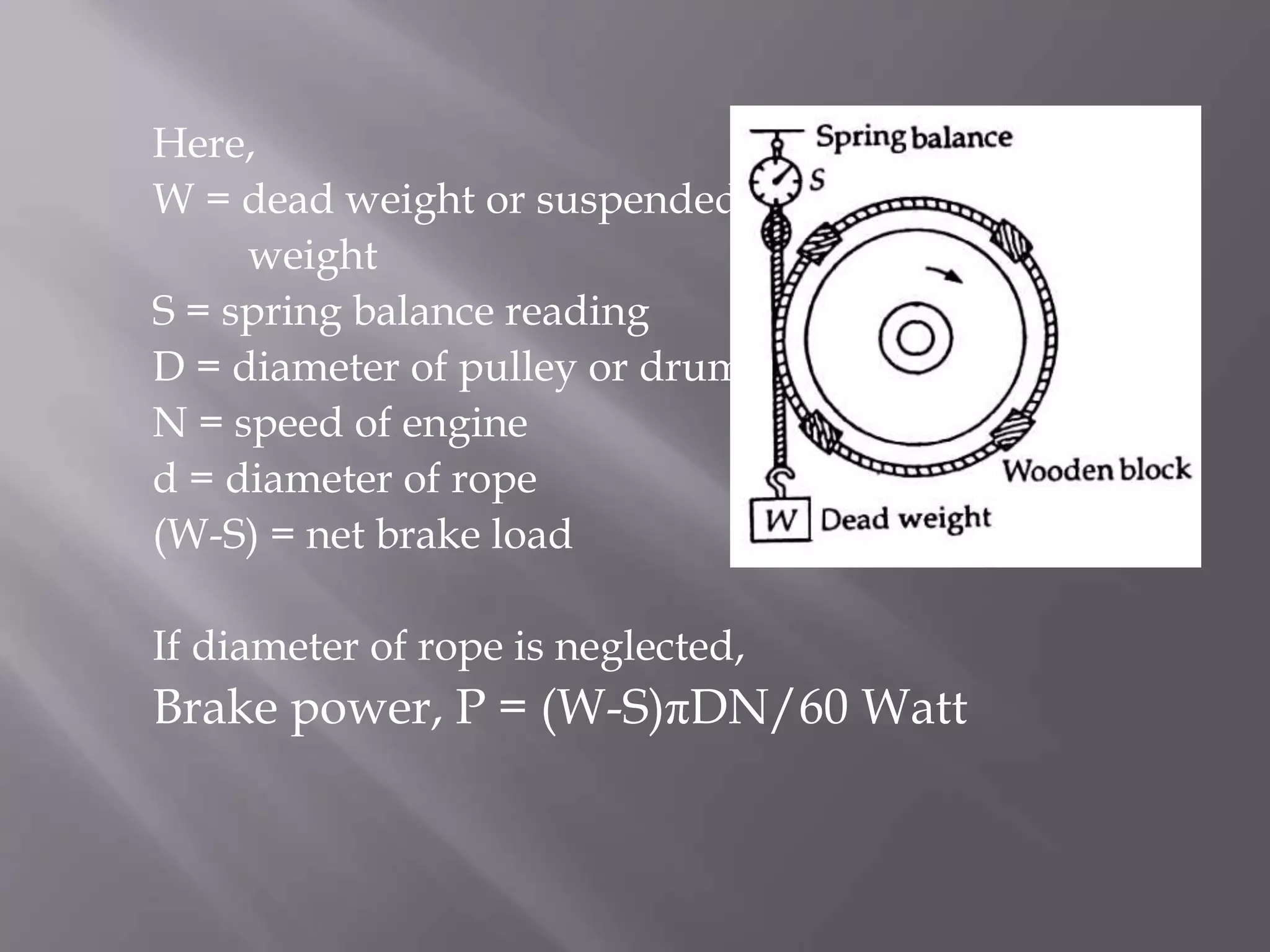


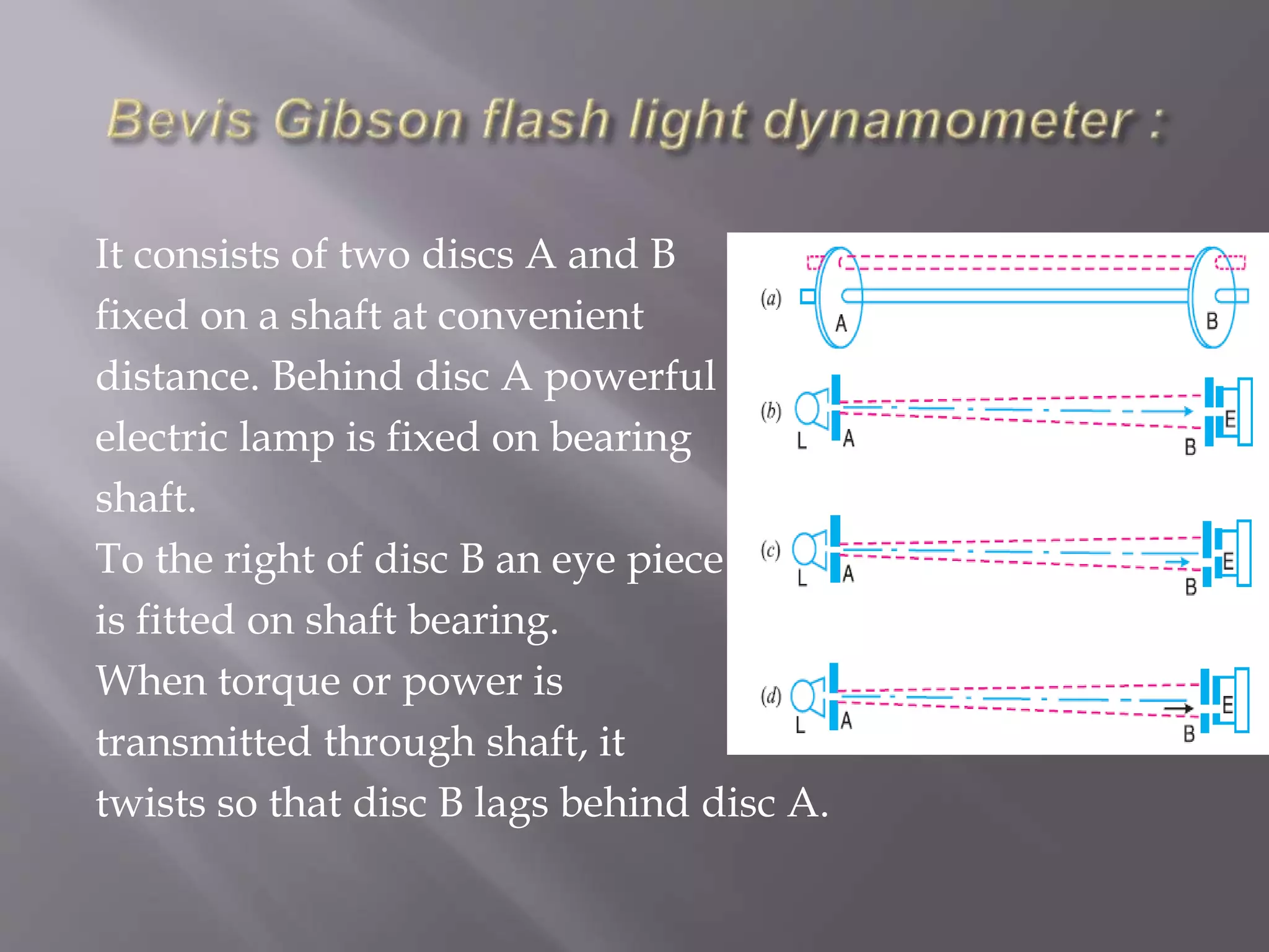


The document discusses the theory and various types of dynamometers used for measuring power absorbed during braking or torque transmission in machines. It outlines different dynamometer types, including absorption (Prony and rope brake) and transmission (belt, epicyclic, and torsion dynamometers), each with specific workings and measurements related to engine power. The document includes equations for calculating brake power and torque based on the dynamometer's design and mechanics.


