2
Dynamometer
A dynamometer isa brake but in addition it has a
device to measure the frictional resistance.
Knowing the frictional resistance, we may obtain
the torque transmitted and hence the power of the
engine.
Types of Dynamometers :
Following are the two types of dynamometers,
used for measuring the brake power of an engine.
1. Absorption dynamometers, and
2. Transmission dynamometers.
3.
3
In the absorptiondynamometers, the entire energy
or power produced by the engine is absorbed by
the friction resistances of the brake and is
transformed into heat, during the process of
measurement.
In the transmission dynamometers, the energy is
not wasted in friction but is used for doing work.
The energy or power produced by the engine is
transmitted through the dynamometer to some
other machines where the power developed is
suitably measured. Ex: Epicyclic train
dynamometer, Belt transmission dynamometer and
Torsional dynamometer.
4.
4
Classification of AbsorptionDynamometers
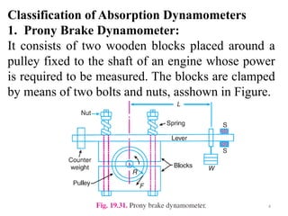
1. Prony Brake Dynamometer:
It consists of two wooden blocks placed around a
pulley fixed to the shaft of an engine whose power
is required to be measured. The blocks are clamped
by means of two bolts and nuts, asshown in Figure.
5.
5
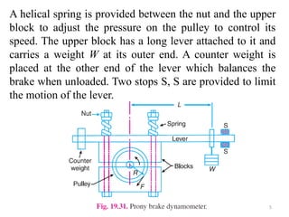
A helical springis provided between the nut and the upper
block to adjust the pressure on the pulley to control its
speed. The upper block has a long lever attached to it and
carries a weight W at its outer end. A counter weight is
placed at the other end of the lever which balances the
brake when unloaded. Two stops S, S are provided to limit
the motion of the lever.
6.
6
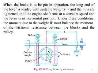
When the brakeis to be put in operation, the long end of
the lever is loaded with suitable weights W and the nuts are
tightened until the engine shaft runs at a constant speed and
the lever is in horizontal position. Under these conditions,
the moment due to the weight W must balance the moment
of the frictional resistance between the blocks and the
pulley.
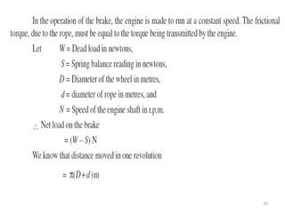
8
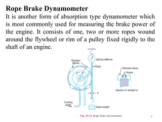
Rope Brake Dynamometer
Itis another form of absorption type dynamometer which
is most commonly used for measuring the brake power of
the engine. It consists of one, two or more ropes wound
around the flywheel or rim of a pulley fixed rigidly to the
shaft of an engine.
9.
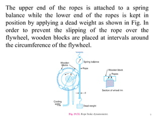
9
The upper endof the ropes is attached to a spring
balance while the lower end of the ropes is kept in
position by applying a dead weight as shown in Fig. In
order to prevent the slipping of the rope over the
flywheel, wooden blocks are placed at intervals around
the circumference of the flywheel.
12
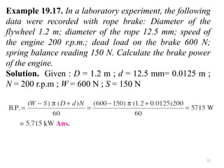
Example 19.17. Ina laboratory experiment, the following
data were recorded with rope brake: Diameter of the
flywheel 1.2 m; diameter of the rope 12.5 mm; speed of
the engine 200 r.p.m.; dead load on the brake 600 N;
spring balance reading 150 N. Calculate the brake power
of the engine.
Solution. Given : D = 1.2 m ; d = 12.5 mm= 0.0125 m ;
N = 200 r.p.m ; W = 600 N ; S = 150 N
13.
13
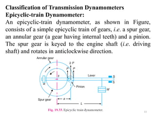
Classification of TransmissionDynamometers
Epicyclic-train Dynamometer:
An epicyclic-train dynamometer, as shown in Figure,
consists of a simple epicyclic train of gears, i.e. a spur gear,
an annular gear (a gear having internal teeth) and a pinion.
The spur gear is keyed to the engine shaft (i.e. driving
shaft) and rotates in anticlockwise direction.
14.
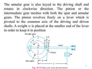
14
The annular gearis also keyed to the driving shaft and
rotates in clockwise direction. The pinion or the
intermediate gear meshes with both the spur and annular
gears. The pinion revolves freely on a lever which is
pivoted to the common axis of the driving and driven
shafts. A weight w is placed at the smaller end of the lever
in order to keep it in position
15.
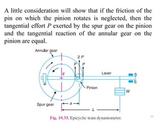
15
A little considerationwill show that if the friction of the
pin on which the pinion rotates is neglected, then the
tangential effort P exerted by the spur gear on the pinion
and the tangential reaction of the annular gear on the
pinion are equal.
16.
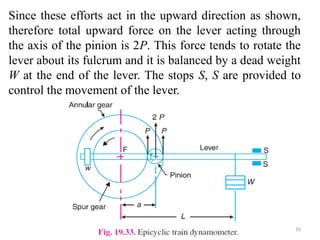
16
Since these effortsact in the upward direction as shown,
therefore total upward force on the lever acting through
the axis of the pinion is 2P. This force tends to rotate the
lever about its fulcrum and it is balanced by a dead weight
W at the end of the lever. The stops S, S are provided to
control the movement of the lever.
18
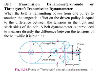
Belt Transmission Dynamometer-Froudeor
Throneycroft Transmission Dynamometer
When the belt is transmitting power from one pulley to
another, the tangential effort on the driven pulley is equal
to the difference between the tensions in the tight and
slack sides of the belt. A belt dynamometer is introduced
to measure directly the difference between the tensions of
the belt,while it is running.
19.
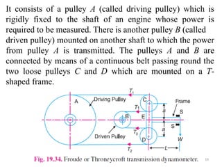
19
It consists ofa pulley A (called driving pulley) which is
rigidly fixed to the shaft of an engine whose power is
required to be measured. There is another pulley B (called
driven pulley) mounted on another shaft to which the power
from pulley A is transmitted. The pulleys A and B are
connected by means of a continuous belt passing round the
two loose pulleys C and D which are mounted on a T-
shaped frame.
20.
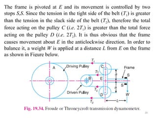
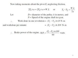
20
The frame ispivoted at E and its movement is controlled by two
stops S,S. Since the tension in the tight side of the belt (T1) is greater
than the tension in the slack side of the belt (T2), therefore the total
force acting on the pulley C (i.e. 2T1) is greater than the total force
acting on the pulley D (i.e. 2T2). It is thus obvious that the frame
causes movement about E in the anticlockwise direction. In order to
balance it, a weight W is applied at a distance L from E on the frame
as shown in Figure below.
22
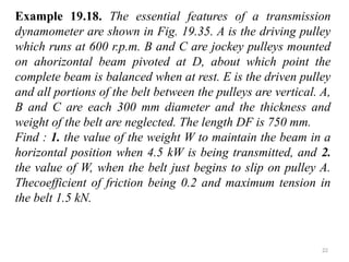
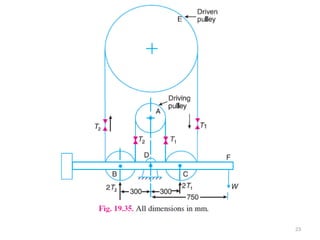
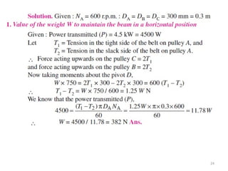
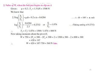
Example 19.18. Theessential features of a transmission
dynamometer are shown in Fig. 19.35. A is the driving pulley
which runs at 600 r.p.m. B and C are jockey pulleys mounted
on ahorizontal beam pivoted at D, about which point the
complete beam is balanced when at rest. E is the driven pulley
and all portions of the belt between the pulleys are vertical. A,
B and C are each 300 mm diameter and the thickness and
weight of the belt are neglected. The length DF is 750 mm.
Find : 1. the value of the weight W to maintain the beam in a
horizontal position when 4.5 kW is being transmitted, and 2.
the value of W, when the belt just begins to slip on pulley A.
Thecoefficient of friction being 0.2 and maximum tension in
the belt 1.5 kN.
26
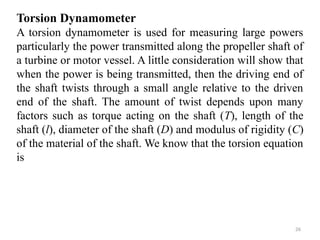
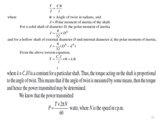
Torsion Dynamometer
A torsiondynamometer is used for measuring large powers
particularly the power transmitted along the propeller shaft of
a turbine or motor vessel. A little consideration will show that
when the power is being transmitted, then the driving end of
the shaft twists through a small angle relative to the driven
end of the shaft. The amount of twist depends upon many
factors such as torque acting on the shaft (T), length of the
shaft (l), diameter of the shaft (D) and modulus of rigidity (C)
of the material of the shaft. We know that the torsion equation
is
28
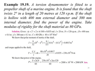
Example 19.19. Atorsion dynamometer is fitted to a
propeller shaft of a marine engine. It is found that the shaft
twists 2° in a length of 20 metres at 120 r.p.m. If the shaft
is hollow with 400 mm external diameter and 300 mm
internal diameter, find the power of the engine. Take
modulus of rigidity for the shaft material as 80 GPa.