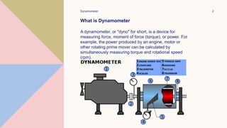
DYNAMOMETER
Ravi Ranjan Prasad
B. Tech 6th Sem ME-1
Exam Roll No- 4047003
Dynamometer 2
What is Dynamometer
A dynamometer, or "dyno" for short, is a device for
measuring force, moment of force (torque), or power. For
example, the power produced by an engine, motor or
other rotating prime mover can be calculated by
simultaneously measuring torque and rotational speed
(rpm).
Applications for Dynamometers
In addition to being used to determine the torque or power characteristics
of a machine under test (MUT), dynamometers are employed in a number
of other roles. In standard emissions testing cycles such as those defined
by the US Environmental Protection Agency (US EPA), dynamometers are
used to provide simulated road loading of either the engine (using an
engine dynamometer) or full powertrain (using a chassis dynamometer). In
fact, beyond simple power and torque measurements, dynamometers can
be used as part of a testbed for a variety of engine development activities
such as the calibration of engine management controllers, detailed
investigations into combustion behavior and tribology.
In an engine dynamometer, water flow, proportional to the desired applied
load, creates resistance to the engine. A controlled water flow through the
inlet manifold is directed at the center of the rotor in each absorption
section. This water is then expelled to the outer dynamometer body by
centrifugal force. As it is directed outward, the water is accelerated into
pockets on the stationary stator plates where it is decelerated. The
continual acceleration and deceleration causes the dynamometer to
absorb the power produced by the engine. Through this transfer of energy
the water is heated and discharged.
Dynamometer 4
Types of Dynamometer
A dynamometer is a device used for measuring the torque
and brake power required to operate a driven machine.
Dynamometers can be broadly classified into two types.
They are:
1. Power Absorption Dynamometers: Power Absorption
dynamometers measure and absorb the power output of the
engine to which they are coupled. The power absorbed is
usually dissipated as heat by some means.
Examples of power absorption dynamometers are
Prony brake dynamometer, Rope brake
dynamometer, Eddy current dynamometer, Hydraulic
dynamometer, etc.
2. Power Transmission Dynamometers: In power
transmission dynamometers the power is transmitted to the
load coupled to the engine after it is indicated on some
scale. These are also called torque meters.
5
Absorption Dynamometers:
Transmission dynamometers are also called torque meters. They
mostly consist of a set of strain-gauges fixed on the rotating shaft and
the torque is measured by the angular deformation of the shaft which
is indicated as the strain the of the strain gauge. A four arm bridge is
used to reduce the effect of temperature, and the gauges are
arranged in pairs such that the effect of axial or transverse load on the
strain gauges is avoided.
6
Prony Brake Dynamometer:
Pony Brake is one of the simplest dynamometers for measuring power
output (brake power). It is to attempt to stop the engine using a brake on
the flywheel and measure the weight which an arm attached to the brake
will support, as it tries to rotate with the flywheel.
The Prony brake shown in the above consists of a wooden block,
frame, rope, brake shoes and flywheel. It works on the principle of
converting power into heat by dry friction. Spring-loaded bolts are
provided to increase the friction by tightening the wooden block.
7
Rope Brake Dynamometer:
The rope brake as shown in below figure is another device for measuring
brake power of an engine. It consists of some turns of rope wound around
the rotating drum attached to the output shaft. One side of the rope is
connected to a spring balance and the other side to a loading device. The
power is absorbed in friction between the rope and the drum. Therefore
drum in rope brake requires cooling.
8
Transmission Dynamometer
In the transmission dynamometer the energy is not wasted in friction
but is used for doing work. The energy or power produced by the
engine is transmitted through the dynamometer to some other
machine where the power developed is suitably measured. It
measure the break power.
A transmission dynamometer doesn't absorb any power during its
processes. Involved are a set of strain gauges which are used to
measure the strain of an object where it is attached. These are
located on an oscillating shaft. The torque is determined by the
angular deformation of the shaft.
9
Belt transmission dynamometer
Froude or Thronecroft transmission dynamometer When the belt is
transmitting power from one pulley to the other, the tangential force on
the driven pulley is equal to the difference between the tension in the
tight and slack sides of the belt.
Belt dynamometers are introduced to directly measure the difference
between the tension of a belt while it is running.
10
Torsion Dynamometer
Torsion dynamometer For testing facilities where torsion dynamometers
are used, it was customary up to now, .the test item, the torsion
dynamometer and to arrange the loading machine one behind the other
in the axial direction. This gives a relatively large axial length for the test
device.
11
Hydraulic Dynamometer
Hydraulic dynamometer works on the principle of dissipating the
power in fluid friction rather than in dry friction.
• In principle its construction is similar to that of a fluid flywheel.
• It consists of an inner rotating member or impeller coupled to the
output shaft of the engine.
• This impeller rotates in a casing filled with fluid.
12
Eddy Current Dynamometer
This comes under the classification of engine dynamometers and these
are accurate, quick response, minimal maintenance, and repeatable
substitution for the water brake technology. The instrument is mainly
implemented for the purpose to calculate different characteristics of the
active mechanical test apparatus. It is also used to know the
performance analysis for gas and water turbines, internal combustion
engines, for both small and medium-sized power motors and for many
others.
Features
The main features of eddy current dynamometers are as follows:
• Enhanced rotational speed
• Minimal inertia moment and residual torque
• The device operates in both clockwise and anti-clockwise directions
• It has constant braking torque and has no shock characteristics
• Braking torque can be measured internally having no use of external device
• Inbuilt optical speed sensor
• The device is available in 13 models having the highest torque value of 399
13
Eddy Current Dynamometer Working Principle
The basic principle of the eddy current dynamometer is dependent on
the Eddy current which means on the right-hand principle of Fleming’s
law. The main components in this device are brake, force evaluation
and speed calculation instrument, and others. Where the brake
controls overloading of the prime mover and it also has the functionality
to alter the absorbed power delivered from the prime mover into heat
and this heat is cooled up internal cooling arrangements.
THANK YOU
Ravi Ranjan Prasad
B. Tech 6th Sem ME-1
Class Roll No- 25736
Exam Roll no-4047003

Ravi Ranjan ppt 4047003.pptx

  • 1.
    DYNAMOMETER Ravi Ranjan Prasad B.Tech 6th Sem ME-1 Exam Roll No- 4047003
  • 2.
    Dynamometer 2 What isDynamometer A dynamometer, or "dyno" for short, is a device for measuring force, moment of force (torque), or power. For example, the power produced by an engine, motor or other rotating prime mover can be calculated by simultaneously measuring torque and rotational speed (rpm).
  • 3.
    Applications for Dynamometers Inaddition to being used to determine the torque or power characteristics of a machine under test (MUT), dynamometers are employed in a number of other roles. In standard emissions testing cycles such as those defined by the US Environmental Protection Agency (US EPA), dynamometers are used to provide simulated road loading of either the engine (using an engine dynamometer) or full powertrain (using a chassis dynamometer). In fact, beyond simple power and torque measurements, dynamometers can be used as part of a testbed for a variety of engine development activities such as the calibration of engine management controllers, detailed investigations into combustion behavior and tribology. In an engine dynamometer, water flow, proportional to the desired applied load, creates resistance to the engine. A controlled water flow through the inlet manifold is directed at the center of the rotor in each absorption section. This water is then expelled to the outer dynamometer body by centrifugal force. As it is directed outward, the water is accelerated into pockets on the stationary stator plates where it is decelerated. The continual acceleration and deceleration causes the dynamometer to absorb the power produced by the engine. Through this transfer of energy the water is heated and discharged.
  • 4.
    Dynamometer 4 Types ofDynamometer A dynamometer is a device used for measuring the torque and brake power required to operate a driven machine. Dynamometers can be broadly classified into two types. They are: 1. Power Absorption Dynamometers: Power Absorption dynamometers measure and absorb the power output of the engine to which they are coupled. The power absorbed is usually dissipated as heat by some means. Examples of power absorption dynamometers are Prony brake dynamometer, Rope brake dynamometer, Eddy current dynamometer, Hydraulic dynamometer, etc. 2. Power Transmission Dynamometers: In power transmission dynamometers the power is transmitted to the load coupled to the engine after it is indicated on some scale. These are also called torque meters.
  • 5.
    5 Absorption Dynamometers: Transmission dynamometersare also called torque meters. They mostly consist of a set of strain-gauges fixed on the rotating shaft and the torque is measured by the angular deformation of the shaft which is indicated as the strain the of the strain gauge. A four arm bridge is used to reduce the effect of temperature, and the gauges are arranged in pairs such that the effect of axial or transverse load on the strain gauges is avoided.
  • 6.
    6 Prony Brake Dynamometer: PonyBrake is one of the simplest dynamometers for measuring power output (brake power). It is to attempt to stop the engine using a brake on the flywheel and measure the weight which an arm attached to the brake will support, as it tries to rotate with the flywheel. The Prony brake shown in the above consists of a wooden block, frame, rope, brake shoes and flywheel. It works on the principle of converting power into heat by dry friction. Spring-loaded bolts are provided to increase the friction by tightening the wooden block.
  • 7.
    7 Rope Brake Dynamometer: Therope brake as shown in below figure is another device for measuring brake power of an engine. It consists of some turns of rope wound around the rotating drum attached to the output shaft. One side of the rope is connected to a spring balance and the other side to a loading device. The power is absorbed in friction between the rope and the drum. Therefore drum in rope brake requires cooling.
  • 8.
    8 Transmission Dynamometer In thetransmission dynamometer the energy is not wasted in friction but is used for doing work. The energy or power produced by the engine is transmitted through the dynamometer to some other machine where the power developed is suitably measured. It measure the break power. A transmission dynamometer doesn't absorb any power during its processes. Involved are a set of strain gauges which are used to measure the strain of an object where it is attached. These are located on an oscillating shaft. The torque is determined by the angular deformation of the shaft.
  • 9.
    9 Belt transmission dynamometer Froudeor Thronecroft transmission dynamometer When the belt is transmitting power from one pulley to the other, the tangential force on the driven pulley is equal to the difference between the tension in the tight and slack sides of the belt. Belt dynamometers are introduced to directly measure the difference between the tension of a belt while it is running.
  • 10.
    10 Torsion Dynamometer Torsion dynamometerFor testing facilities where torsion dynamometers are used, it was customary up to now, .the test item, the torsion dynamometer and to arrange the loading machine one behind the other in the axial direction. This gives a relatively large axial length for the test device.
  • 11.
    11 Hydraulic Dynamometer Hydraulic dynamometerworks on the principle of dissipating the power in fluid friction rather than in dry friction. • In principle its construction is similar to that of a fluid flywheel. • It consists of an inner rotating member or impeller coupled to the output shaft of the engine. • This impeller rotates in a casing filled with fluid.
  • 12.
    12 Eddy Current Dynamometer Thiscomes under the classification of engine dynamometers and these are accurate, quick response, minimal maintenance, and repeatable substitution for the water brake technology. The instrument is mainly implemented for the purpose to calculate different characteristics of the active mechanical test apparatus. It is also used to know the performance analysis for gas and water turbines, internal combustion engines, for both small and medium-sized power motors and for many others. Features The main features of eddy current dynamometers are as follows: • Enhanced rotational speed • Minimal inertia moment and residual torque • The device operates in both clockwise and anti-clockwise directions • It has constant braking torque and has no shock characteristics • Braking torque can be measured internally having no use of external device • Inbuilt optical speed sensor • The device is available in 13 models having the highest torque value of 399
  • 13.
    13 Eddy Current DynamometerWorking Principle The basic principle of the eddy current dynamometer is dependent on the Eddy current which means on the right-hand principle of Fleming’s law. The main components in this device are brake, force evaluation and speed calculation instrument, and others. Where the brake controls overloading of the prime mover and it also has the functionality to alter the absorbed power delivered from the prime mover into heat and this heat is cooled up internal cooling arrangements.
  • 14.
    THANK YOU Ravi RanjanPrasad B. Tech 6th Sem ME-1 Class Roll No- 25736 Exam Roll no-4047003