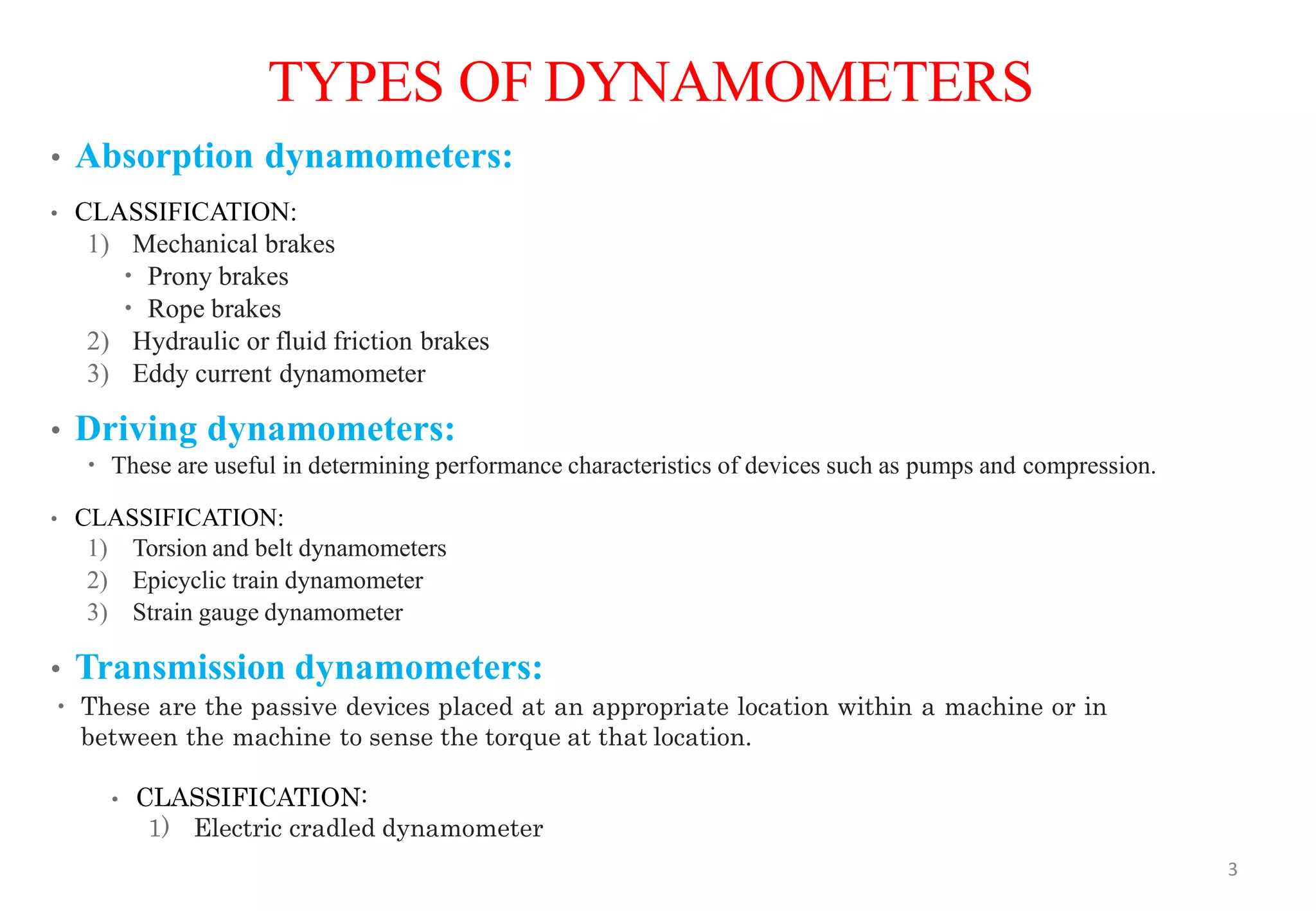
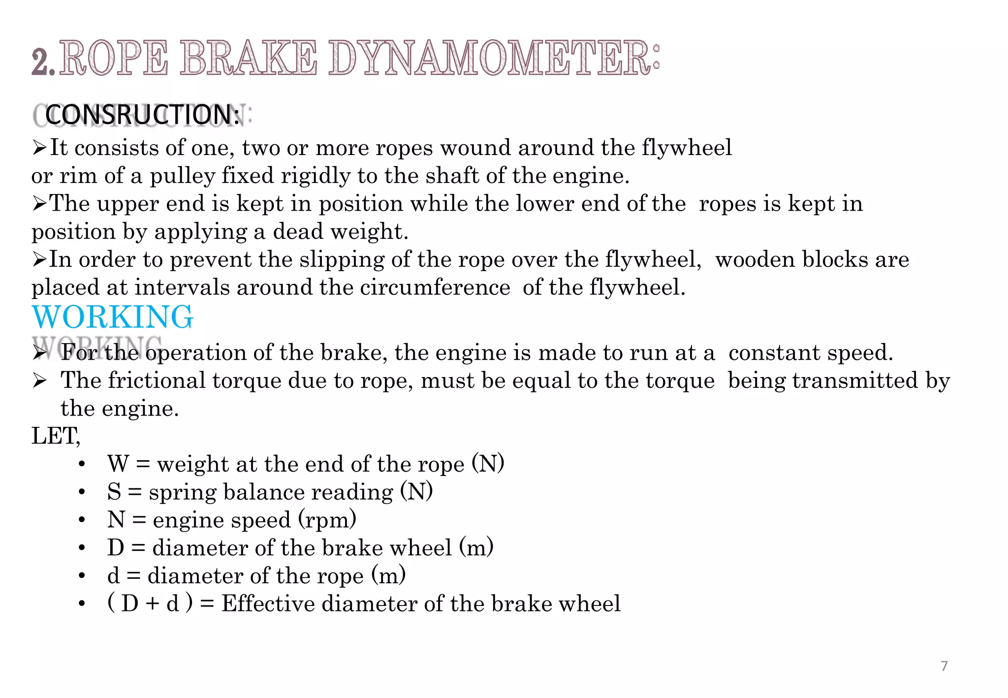
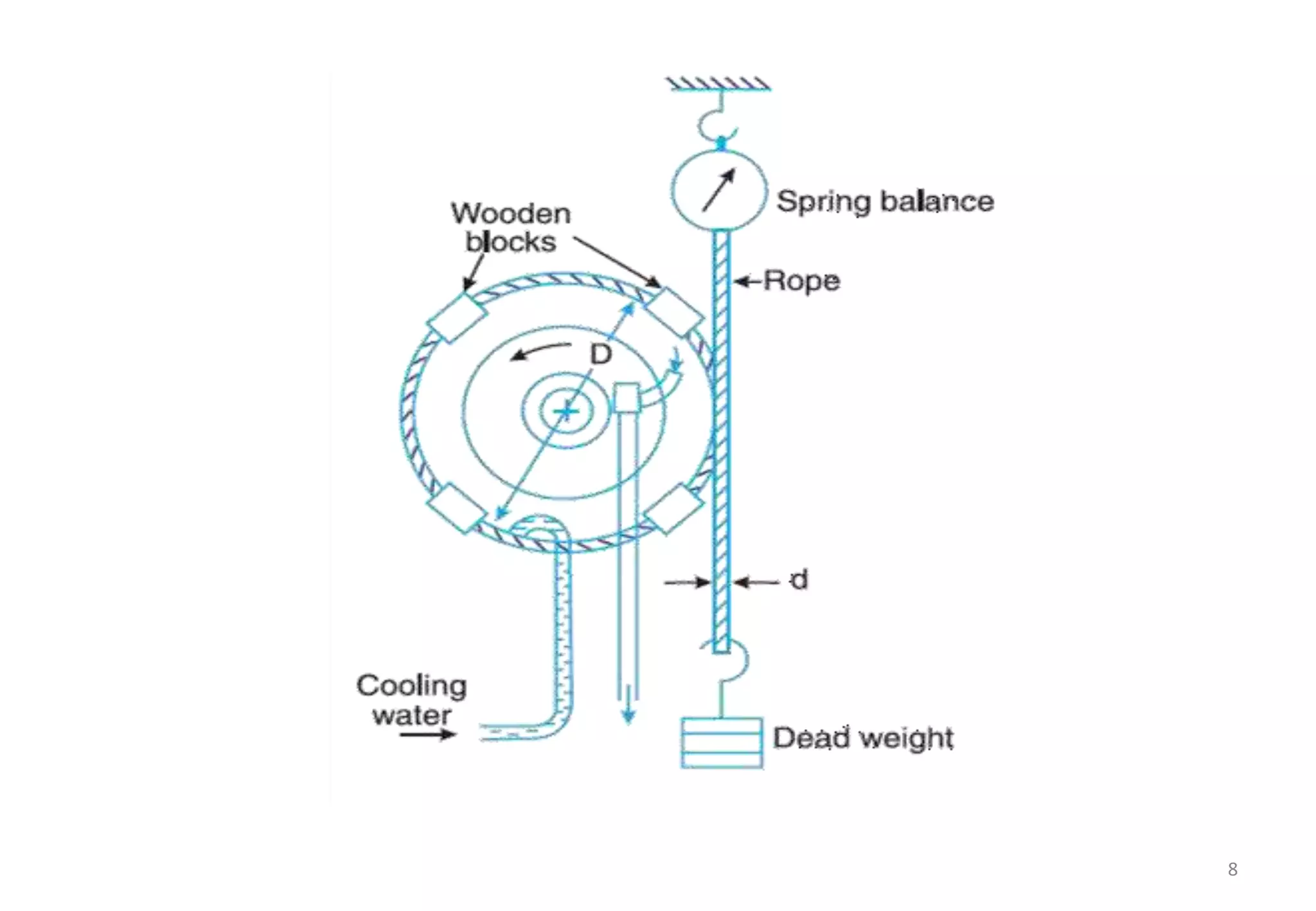
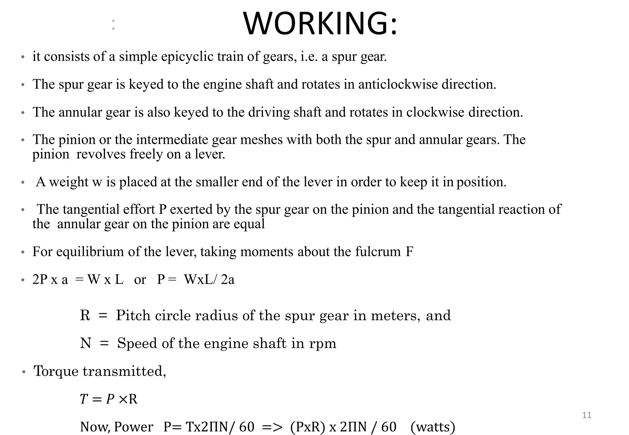
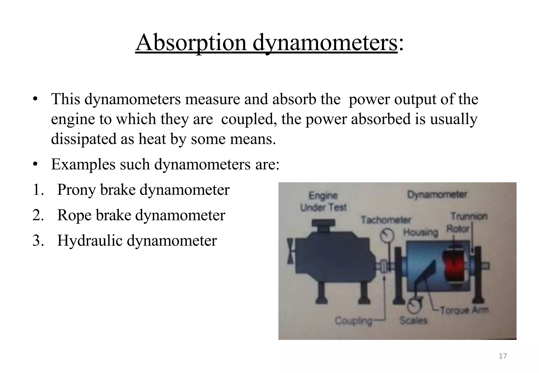
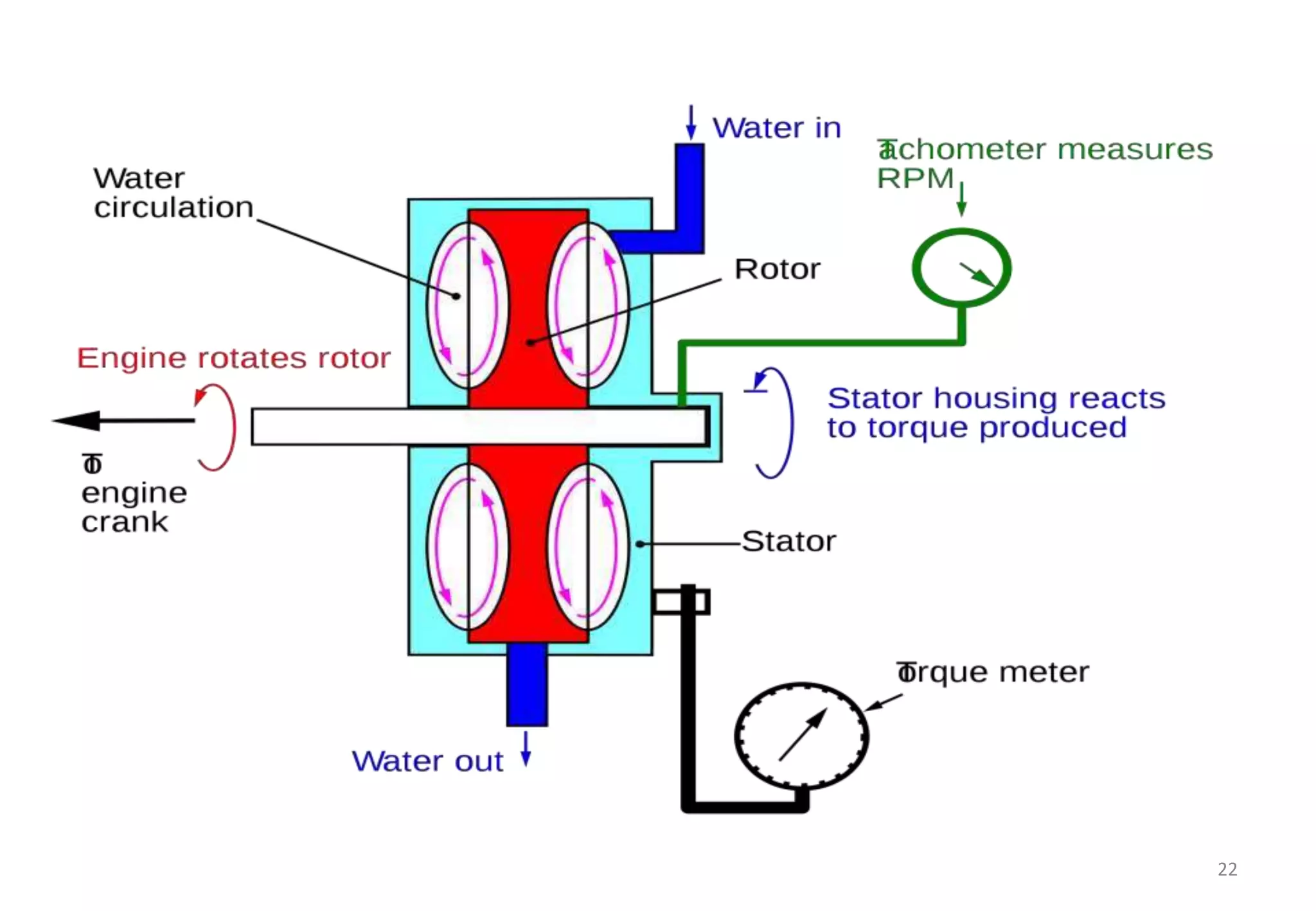
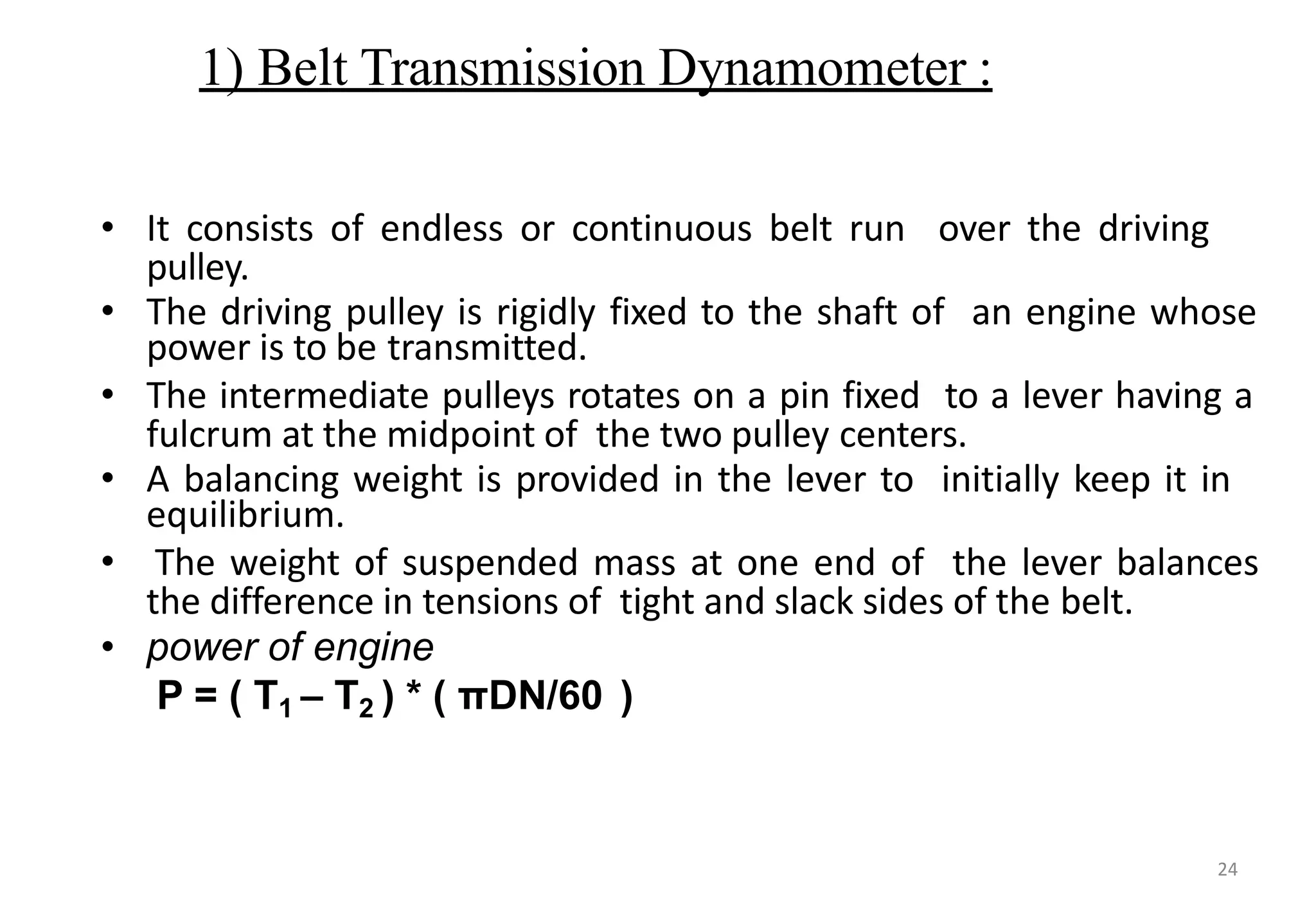
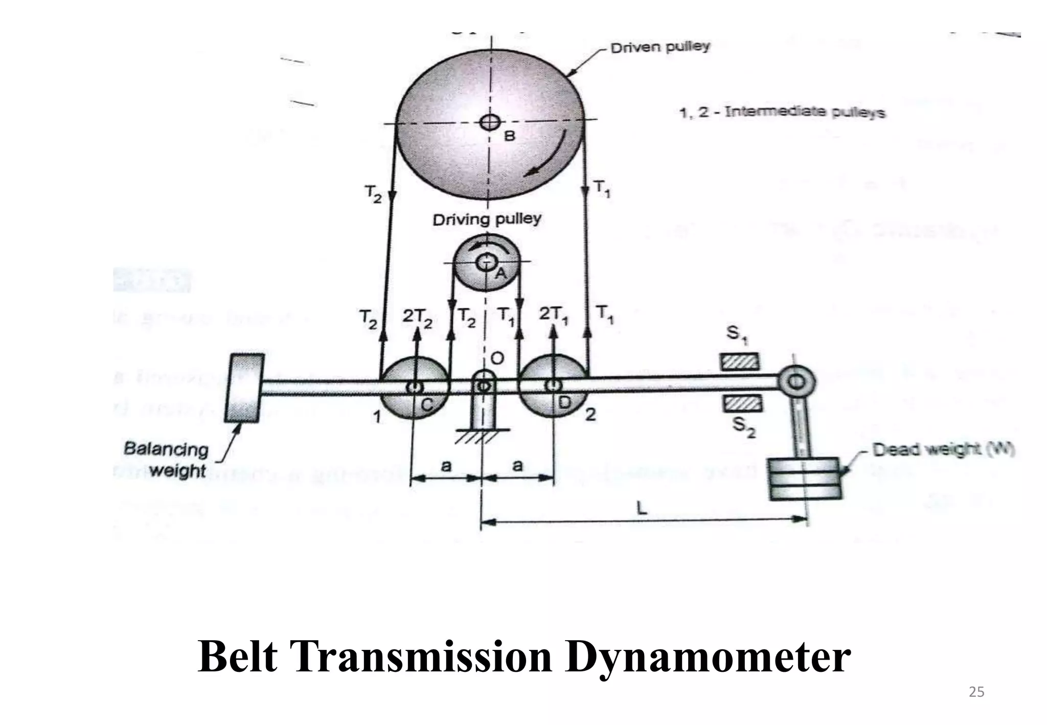
UNIT-II
Measurement of
shaft power
1
METHODS FOR MEASURING TORQUE
Torque measuring devices are called as dynamometers.
Torque measurement is usually associated with determination of
mechanical power, either power required to operate a machine or to
find out the power developed by the machine.
• where,
o P = power developed by machine (watt)
o N = rotation of shaft (rpm)
o T = torque (Nm)
2
TYPES OF DYNAMOMETERS
• Absorption dynamometers:
• CLASSIFICATION:
1) Mechanical brakes
 Prony brakes
 Rope brakes
2) Hydraulic or fluid friction brakes
3) Eddy current dynamometer
• Driving dynamometers:
 These are useful in determining performance characteristics of devices such as pumps and compression.
• CLASSIFICATION:
1) Torsion and belt dynamometers
2) Epicyclic train dynamometer
3) Strain gauge dynamometer
• Transmission dynamometers:
 These are the passive devices placed at an appropriate location within a machine or in
between the machine to sense the torque at that location.
• CLASSIFICATION:
1) Electric cradled dynamometer
3
ABSORPTION DYNAMOMETERS
• WORKING PRINCIPLE:
the power measured is converted into heat by friction or by other means.
4
CONSTRUCTION
 It consists of two wooden blocks placed around a pulley fixed to the shaft of an
engine whose power is required to be measured.
 Blocks are clamped by means of bolts and nuts. A helical spring is provided between
the nut
and the upper block to adjust the pressure on the pulley to control its speed.
 The upper block has a long lever attached to it and carries a weight W at its outer
end. A counter weight is placed at the other end of the lever which balances the
brake when unloaded.
 In order to limit the motion of the lever, two stops provided.
WORKING
 When the brake is to be operated, the long end of lever is loaded with suitable
weights W and nuts are tightened until the engine shaft runs at a constant speed
and the lever is in horizontal position.
 Under these conditions, the moment due to the weight W must balance the moment
of frictional
resistance between the blocks and the pulley.
5
 LET,
 W = weight at the outer end of the lever (Newton)
 L = horizontal distance of the weight W from the center of
the pulley (meter)
 R = radius of the pulley (meter)
 N = speed of the shaft (rpm)
 Now, the moment of the frictional resistance or torque of
the shaft,
 𝑇 = 𝑊 × 𝐿 (Nm)
𝐵𝑟𝑎𝑘𝑒 𝑝𝑜𝑤𝑒𝑟 = 𝑇×2𝜋𝑁
=(𝑊×𝐿)×2𝜋𝑁
60 60
(Watts)
LIMITATIONS
when the driving torque on the shaft is not uniform, this dynamometer is subjected
to serve oscillations.
APPLIATIONS
measuring power or torque developed by power source such as engines or electric
motors. 6
CONSRUCTION:
It consists of one, two or more ropes wound around the flywheel
or rim of a pulley fixed rigidly to the shaft of the engine.
The upper end is kept in position while the lower end of the ropes is kept in
position by applying a dead weight.
In order to prevent the slipping of the rope over the flywheel, wooden blocks are
placed at intervals around the circumference of the flywheel.
WORKING
 For the operation of the brake, the engine is made to run at a constant speed.
 The frictional torque due to rope, must be equal to the torque being transmitted by
the engine.
LET,
• W = weight at the end of the rope (N)
• S = spring balance reading (N)
• N = engine speed (rpm)
• D = diameter of the brake wheel (m)
• d = diameter of the rope (m)
• ( D + d ) = Effective diameter of the brake wheel
7
8
ADVANTAGE
 Cheap and easy construction
LIMITATIONS
 Its not accurate because of change in friction coefficient of the rope
with temperature.
APPLICATIONS
 This type of absorption dynamometer is most commonly used. 9
DRIVING DYNAMOMETERS
• Working principle:
These dynamometers measure power or torque and as well provide energy to
operate the device to be
tested.
10
WORKING:
• it consists of a simple epicyclic train of gears, i.e. a spur gear.
• The spur gear is keyed to the engine shaft and rotates in anticlockwise direction.
• The annular gear is also keyed to the driving shaft and rotates in clockwise direction.
• The pinion or the intermediate gear meshes with both the spur and annular gears. The
pinion revolves freely on a lever.
• A weight w is placed at the smaller end of the lever in order to keep it in position.
• The tangential effort P exerted by the spur gear on the pinion and the tangential reaction of
the annular gear on the pinion are equal
• For equilibrium of the lever, taking moments about the fulcrum F
• 2P x a = W x L or P = WxL/ 2a
R = Pitch circle radius of the spur gear in meters, and
N = Speed of the engine shaft in rpm
• Torque transmitted,
𝑇 = 𝑃 ×R
Now, Power P= Tx2ΠN/ 60 => (PxR) x 2ΠN / 60 (watts)
11
WORKING PRINCIPAL:
When power is being transmitted by the belt from one pulley to another,
the tangential effort on the driven pulley is equal to the difference between the
tension in the tight and slack sides of the belt.
 A belt transmission dynamometer, is called a Froude or Throneycraft
transmission dynamometer. 12
CONSTRUCTION:
• It consists of a pulley A (called driving pulley) which is rigidly fixed tothe shaft of an
engine
whose power is required to be measured.
• There is another pulley B (called driven pulley) mounted on another shaft to which
the power from pulley A is transmitted. The pulleys
• A and B are connected by means of a continuous belt passing round the two loose
pulleys C and D which are mounted on a T-shaped frame.
• The frame is pivoted at E and its movement is controlled by two stops.
WORKING:
• Since the tension in the tight side of the belt (T1) is greater than the tension in the
slack side of the belt (T2),so the total force acting on the pulley C (i.e. 2T1) is greater
than the total force acting on the pulley D (i.e. 2T2).
• It is thus obvious that the frame causes movement about E in the anticlockwise
direction.
• In order to balance it, a weight W is applied at a distance L from E on the frame.
• Now taking moments about the pivot E, neglecting friction,
13
(Nm)• Work done in one revolution= (𝑇1− 𝑇2)𝜋𝐷
• workdone per minute= (𝑇1− 𝑇2)𝜋𝐷𝑁 (Nm)
60
• Brake power = (𝑇1−𝑇2)𝜋𝐷𝑁
(Watts)
14
INTRODUCTION
Definition:
Dynamometer is a device which is used to measure the
frictional resistance. By know ing frictional resistance we can
determine the torque transmitted and hence the power of the
engine.
15
Types of dynamometers:
1)Absorption dynamometer:
 Prony brake dynamometer
 Rope brake dynamometer
 Hydraulic dynamometer
2) Transmission dynamometer:
 Belt transmission dynamometer
 Epicyclic dynamometer
 Torsion dynamometer
16
Absorption dynamometers:
• This dynamometers measure and absorb the power output of the
engine to which they are coupled, the power absorbed is usually
dissipated as heat by some means.
• Examples such dynamometers are:
1. Prony brake dynamometer
2. Rope brake dynamometer
3. Hydraulic dynamometer
17
Prony brake dynamometer
• A simplest form of an Absorption type Dynamometer is a Prony
Brake Dynamometer . It consists of Two wooden blocks around a
Pulley fixed to the shaft of an engine , whose power is required to
be measured . The blocks are clamped by means of Two Bolts and
Nuts . A Helical Spring is provided between the nut and the upper
block to adjust the Pressure on the Pulley to Control its Speed . The
upper block has a long lever attached to it and carries a weight W at
its outer end . A Counter Weight is placed at the other end of the
lever which balances the Brake when Unloaded . Two stops S1 and
S2 are provided to limit the motion of the Lever .
18
-In Prony Brake Dynamometer , when the Brake is to be put in
operation , the long end of the lever is loaded with suitable weights
W and the nuts are tightened until the engine shaft runs at a constant
speed and the lever is in Horizontal Position . Under these
conditions
, the moment due to the weight W must balance the moment of the
Frictional Resistance between the Blocks and Pulleys .
Work done per Minute = T * 2πN N-m
Brake Power of the Engine = B.P. = ( Work done per minute ) / ( 60
)
= (T * 2πN / 60 )
= ( W * L * 2πN / 60 )
Watts
19
Rope brake dynamometer:
• It is another form of Absorption type Dynamometer which is most
commonly used for measuring the Brake Power of the Engine . It consists
of one , two or more ropes wound around the flywheel or rim of a pulley
fixed rigidly to the shaft of an engine . The upper end of the ropes is
attached to a spring balance while the lower end of the ropes is kept in
position by applying a dead weigBrake Power of the Engine = B.P. = (
Work done per minute ) / ( 60 )
= ( W – S ) * π * ( D + d ) * N / 60 Watts
If the Diameter of the Rope (d) is neglected , then Brake Power of the
Engine, B.P. = ( W – S ) * ( πDN/60 ) Watts
20
Hydraulic dynamometer:
• It works on the principle of dissipating the power in fluid
friction rather than in dry friction.
• It consists of an inner rotating member or impeller coupled to
the output shaft of engine, this impeller rotates in a casing
filled with fluid.
• The heat developed due to dissipation of power is carried away
by a continuous supply of working fluid, usually water.
• The output can be controlled by regulating the sluice gates which
can be moved in and out to partial or wholly obstructive flow of
water between impeller and the casing.
21
22
Transmission Dynamometers :
• Power-measuring dynamometers may
be transmission dynamometers or absorption dynamometers. The
former utilize devices that measure torque, in terms of the elastic twist of
the shaft or of a special torquemeter inserted between sections of the
shaft. The torque is produced by the useful load that the prime mover,
motor, or machine is carrying.
23
1) Belt Transmission Dynamometer :
• It consists of endless or continuous belt run over the driving
pulley.
• The driving pulley is rigidly fixed to the shaft of an engine whose
power is to be transmitted.
• The intermediate pulleys rotates on a pin fixed to a lever having a
fulcrum at the midpoint of the two pulley centers.
• A balancing weight is provided in the lever to initially keep it in
equilibrium.
• The weight of suspended mass at one end of the lever balances
the difference in tensions of tight and slack sides of the belt.
• power of engine
P = ( T1 – T2 ) * ( πDN/60 )
24
Belt Transmission Dynamometer
25

Measurement of power

  • 1.
  • 2.
    METHODS FOR MEASURINGTORQUE Torque measuring devices are called as dynamometers. Torque measurement is usually associated with determination of mechanical power, either power required to operate a machine or to find out the power developed by the machine. • where, o P = power developed by machine (watt) o N = rotation of shaft (rpm) o T = torque (Nm) 2
  • 3.
    TYPES OF DYNAMOMETERS •Absorption dynamometers: • CLASSIFICATION: 1) Mechanical brakes  Prony brakes  Rope brakes 2) Hydraulic or fluid friction brakes 3) Eddy current dynamometer • Driving dynamometers:  These are useful in determining performance characteristics of devices such as pumps and compression. • CLASSIFICATION: 1) Torsion and belt dynamometers 2) Epicyclic train dynamometer 3) Strain gauge dynamometer • Transmission dynamometers:  These are the passive devices placed at an appropriate location within a machine or in between the machine to sense the torque at that location. • CLASSIFICATION: 1) Electric cradled dynamometer 3
  • 4.
    ABSORPTION DYNAMOMETERS • WORKINGPRINCIPLE: the power measured is converted into heat by friction or by other means. 4
  • 5.
    CONSTRUCTION  It consistsof two wooden blocks placed around a pulley fixed to the shaft of an engine whose power is required to be measured.  Blocks are clamped by means of bolts and nuts. A helical spring is provided between the nut and the upper block to adjust the pressure on the pulley to control its speed.  The upper block has a long lever attached to it and carries a weight W at its outer end. A counter weight is placed at the other end of the lever which balances the brake when unloaded.  In order to limit the motion of the lever, two stops provided. WORKING  When the brake is to be operated, the long end of lever is loaded with suitable weights W and nuts are tightened until the engine shaft runs at a constant speed and the lever is in horizontal position.  Under these conditions, the moment due to the weight W must balance the moment of frictional resistance between the blocks and the pulley. 5
  • 6.
     LET,  W= weight at the outer end of the lever (Newton)  L = horizontal distance of the weight W from the center of the pulley (meter)  R = radius of the pulley (meter)  N = speed of the shaft (rpm)  Now, the moment of the frictional resistance or torque of the shaft,  𝑇 = 𝑊 × 𝐿 (Nm) 𝐵𝑟𝑎𝑘𝑒 𝑝𝑜𝑤𝑒𝑟 = 𝑇×2𝜋𝑁 =(𝑊×𝐿)×2𝜋𝑁 60 60 (Watts) LIMITATIONS when the driving torque on the shaft is not uniform, this dynamometer is subjected to serve oscillations. APPLIATIONS measuring power or torque developed by power source such as engines or electric motors. 6
  • 7.
    CONSRUCTION: It consists ofone, two or more ropes wound around the flywheel or rim of a pulley fixed rigidly to the shaft of the engine. The upper end is kept in position while the lower end of the ropes is kept in position by applying a dead weight. In order to prevent the slipping of the rope over the flywheel, wooden blocks are placed at intervals around the circumference of the flywheel. WORKING  For the operation of the brake, the engine is made to run at a constant speed.  The frictional torque due to rope, must be equal to the torque being transmitted by the engine. LET, • W = weight at the end of the rope (N) • S = spring balance reading (N) • N = engine speed (rpm) • D = diameter of the brake wheel (m) • d = diameter of the rope (m) • ( D + d ) = Effective diameter of the brake wheel 7
  • 8.
  • 9.
    ADVANTAGE  Cheap andeasy construction LIMITATIONS  Its not accurate because of change in friction coefficient of the rope with temperature. APPLICATIONS  This type of absorption dynamometer is most commonly used. 9
  • 10.
    DRIVING DYNAMOMETERS • Workingprinciple: These dynamometers measure power or torque and as well provide energy to operate the device to be tested. 10
  • 11.
    WORKING: • it consistsof a simple epicyclic train of gears, i.e. a spur gear. • The spur gear is keyed to the engine shaft and rotates in anticlockwise direction. • The annular gear is also keyed to the driving shaft and rotates in clockwise direction. • The pinion or the intermediate gear meshes with both the spur and annular gears. The pinion revolves freely on a lever. • A weight w is placed at the smaller end of the lever in order to keep it in position. • The tangential effort P exerted by the spur gear on the pinion and the tangential reaction of the annular gear on the pinion are equal • For equilibrium of the lever, taking moments about the fulcrum F • 2P x a = W x L or P = WxL/ 2a R = Pitch circle radius of the spur gear in meters, and N = Speed of the engine shaft in rpm • Torque transmitted, 𝑇 = 𝑃 ×R Now, Power P= Tx2ΠN/ 60 => (PxR) x 2ΠN / 60 (watts) 11
  • 12.
    WORKING PRINCIPAL: When poweris being transmitted by the belt from one pulley to another, the tangential effort on the driven pulley is equal to the difference between the tension in the tight and slack sides of the belt.  A belt transmission dynamometer, is called a Froude or Throneycraft transmission dynamometer. 12
  • 13.
    CONSTRUCTION: • It consistsof a pulley A (called driving pulley) which is rigidly fixed tothe shaft of an engine whose power is required to be measured. • There is another pulley B (called driven pulley) mounted on another shaft to which the power from pulley A is transmitted. The pulleys • A and B are connected by means of a continuous belt passing round the two loose pulleys C and D which are mounted on a T-shaped frame. • The frame is pivoted at E and its movement is controlled by two stops. WORKING: • Since the tension in the tight side of the belt (T1) is greater than the tension in the slack side of the belt (T2),so the total force acting on the pulley C (i.e. 2T1) is greater than the total force acting on the pulley D (i.e. 2T2). • It is thus obvious that the frame causes movement about E in the anticlockwise direction. • In order to balance it, a weight W is applied at a distance L from E on the frame. • Now taking moments about the pivot E, neglecting friction, 13
  • 14.
    (Nm)• Work donein one revolution= (𝑇1− 𝑇2)𝜋𝐷 • workdone per minute= (𝑇1− 𝑇2)𝜋𝐷𝑁 (Nm) 60 • Brake power = (𝑇1−𝑇2)𝜋𝐷𝑁 (Watts) 14
  • 15.
    INTRODUCTION Definition: Dynamometer is adevice which is used to measure the frictional resistance. By know ing frictional resistance we can determine the torque transmitted and hence the power of the engine. 15
  • 16.
    Types of dynamometers: 1)Absorptiondynamometer:  Prony brake dynamometer  Rope brake dynamometer  Hydraulic dynamometer 2) Transmission dynamometer:  Belt transmission dynamometer  Epicyclic dynamometer  Torsion dynamometer 16
  • 17.
    Absorption dynamometers: • Thisdynamometers measure and absorb the power output of the engine to which they are coupled, the power absorbed is usually dissipated as heat by some means. • Examples such dynamometers are: 1. Prony brake dynamometer 2. Rope brake dynamometer 3. Hydraulic dynamometer 17
  • 18.
    Prony brake dynamometer •A simplest form of an Absorption type Dynamometer is a Prony Brake Dynamometer . It consists of Two wooden blocks around a Pulley fixed to the shaft of an engine , whose power is required to be measured . The blocks are clamped by means of Two Bolts and Nuts . A Helical Spring is provided between the nut and the upper block to adjust the Pressure on the Pulley to Control its Speed . The upper block has a long lever attached to it and carries a weight W at its outer end . A Counter Weight is placed at the other end of the lever which balances the Brake when Unloaded . Two stops S1 and S2 are provided to limit the motion of the Lever . 18
  • 19.
    -In Prony BrakeDynamometer , when the Brake is to be put in operation , the long end of the lever is loaded with suitable weights W and the nuts are tightened until the engine shaft runs at a constant speed and the lever is in Horizontal Position . Under these conditions , the moment due to the weight W must balance the moment of the Frictional Resistance between the Blocks and Pulleys . Work done per Minute = T * 2πN N-m Brake Power of the Engine = B.P. = ( Work done per minute ) / ( 60 ) = (T * 2πN / 60 ) = ( W * L * 2πN / 60 ) Watts 19
  • 20.
    Rope brake dynamometer: •It is another form of Absorption type Dynamometer which is most commonly used for measuring the Brake Power of the Engine . It consists of one , two or more ropes wound around the flywheel or rim of a pulley fixed rigidly to the shaft of an engine . The upper end of the ropes is attached to a spring balance while the lower end of the ropes is kept in position by applying a dead weigBrake Power of the Engine = B.P. = ( Work done per minute ) / ( 60 ) = ( W – S ) * π * ( D + d ) * N / 60 Watts If the Diameter of the Rope (d) is neglected , then Brake Power of the Engine, B.P. = ( W – S ) * ( πDN/60 ) Watts 20
  • 21.
    Hydraulic dynamometer: • Itworks on the principle of dissipating the power in fluid friction rather than in dry friction. • It consists of an inner rotating member or impeller coupled to the output shaft of engine, this impeller rotates in a casing filled with fluid. • The heat developed due to dissipation of power is carried away by a continuous supply of working fluid, usually water. • The output can be controlled by regulating the sluice gates which can be moved in and out to partial or wholly obstructive flow of water between impeller and the casing. 21
  • 22.
  • 23.
    Transmission Dynamometers : •Power-measuring dynamometers may be transmission dynamometers or absorption dynamometers. The former utilize devices that measure torque, in terms of the elastic twist of the shaft or of a special torquemeter inserted between sections of the shaft. The torque is produced by the useful load that the prime mover, motor, or machine is carrying. 23
  • 24.
    1) Belt TransmissionDynamometer : • It consists of endless or continuous belt run over the driving pulley. • The driving pulley is rigidly fixed to the shaft of an engine whose power is to be transmitted. • The intermediate pulleys rotates on a pin fixed to a lever having a fulcrum at the midpoint of the two pulley centers. • A balancing weight is provided in the lever to initially keep it in equilibrium. • The weight of suspended mass at one end of the lever balances the difference in tensions of tight and slack sides of the belt. • power of engine P = ( T1 – T2 ) * ( πDN/60 ) 24
  • 25.