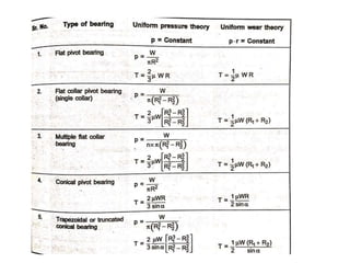
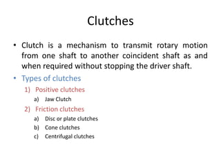
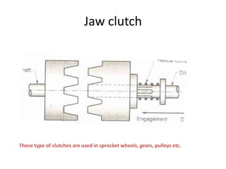
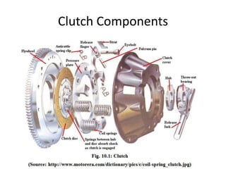
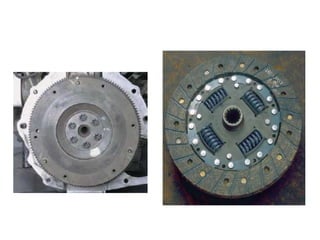
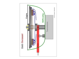
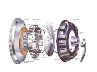
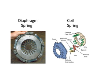
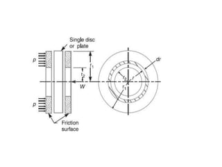
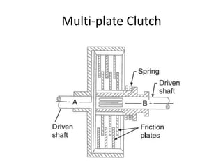
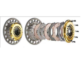
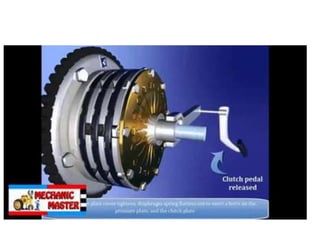
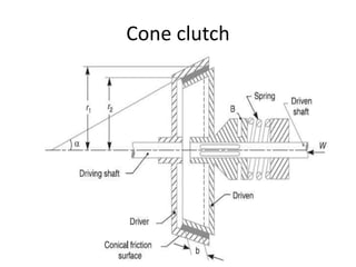
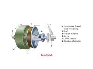
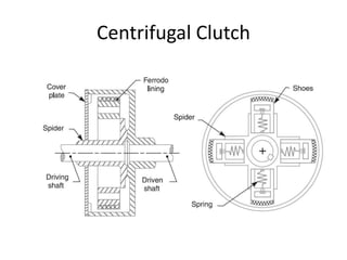
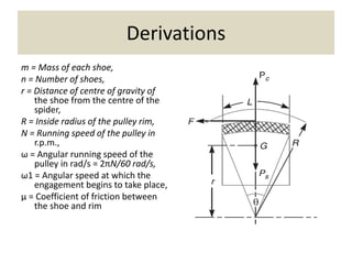
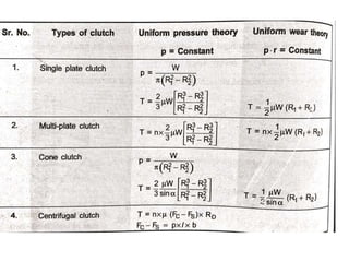
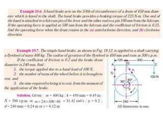
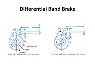
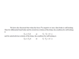
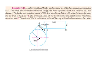
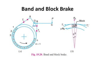
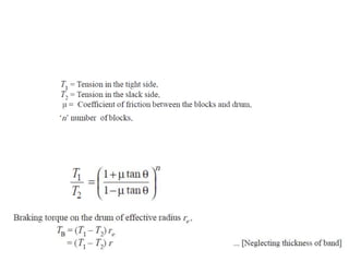
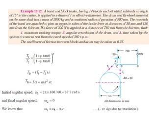
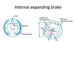
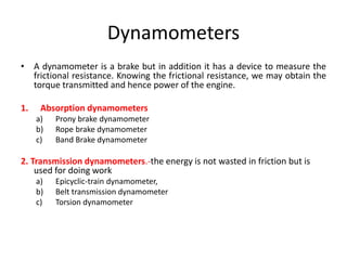
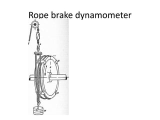
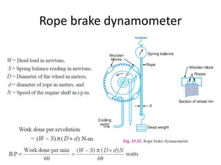
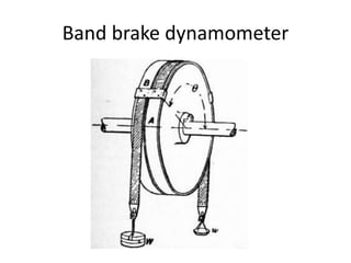
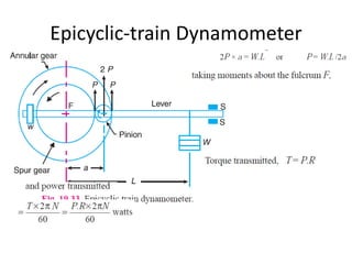
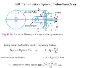
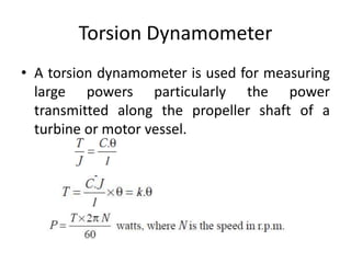
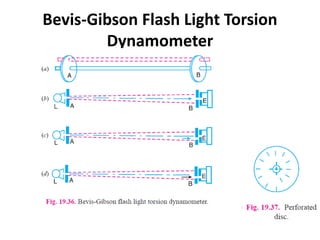
Prof A B Karpe
By
Prof. A B Karpe
Karpe.ajit@gmail.com
Department of Mechanical Engineering
STES’s, Smt. Kashibai Navale College of Engineering
Content
• Clutches (Theory and Numerical)
Pivot and collar friction, Classification of Clutches,
Torque Transmitting Capacity.
• Brakes (Theory and Numerical)
Different types of brakes, shoe brakes, external and internal
shoe brakes, block brakes, band brakes, Band and block
brakes, Braking torques
• Dynamometers (Theory)
Different types of absorption and transmission type
Clutches (Theory and Numerical)
• Uniform Pressure and Uniform Wear Theory
• Pivot and collar friction
• Plate clutches
• Cone clutches
• Centrifugal clutch
Uniform Pressure Theory
In a new bearing, the contact between the
shaft & bearing may be good over the whole
surface. So pressure over the rubbing surfaces
is uniformly distributed.
Here,
p = constant.
Uniform Wear Theory
When the bearing becomes old, all parts of
the rubbing surfaces will not move with the
same velocity. Velocity of rubbing increases
with distance from the axis of bearing. Hence,
wear may be different at different radii.
Rate of wear α p
Rate of wear α v
Uniform wear theory
But, v α r ………….. (v= r ω)
So,
Rate of wear α p .v
Rate of wear α p.r ……….(as v α r)
pr = constant (c)
P (max) x r(min) = P (min) x r(max) = c
Pivot Bearing
Flat Pivot Bearing
Collar Flat Pivot Bearing
Multiple Collars
Conical pivot
bearing
Trapezoidal or
Truncated conical pivot
Clutches
• Clutch is a mechanism to transmit rotary motion
from one shaft to another coincident shaft as and
when required without stopping the driver shaft.
• Types of clutches
1) Positive clutches
a) Jaw Clutch
2) Friction clutches
a) Disc or plate clutches
b) Cone clutches
c) Centrifugal clutches
Jaw clutch
These type of clutches are used in sprocket wheels, gears, pulleys etc.
Single plate clutch
Clutch Components
Diaphragm Coil
Spring Spring
Multi-plate Clutch
Cone clutch
Centrifugal Clutch
Derivations
m = Mass of each shoe,
n = Number of shoes,
r = Distance of centre of gravity of
the shoe from the centre of the
spider,
R = Inside radius of the pulley rim,
N = Running speed of the pulley in
r.p.m.,
ω = Angular running speed of the
pulley in rad/s = 2πN/60 rad/s,
ω1 = Angular speed at which the
engagement begins to take place,
μ = Coefficient of friction between
the shoe and rim
Torque
Pc = m.ω2.r
Ps = m (ω1)2 r
The net outward radial force= Pc – Ps
T = μ (Pc – Ps) R × n = n.F.R
Torque
l = Contact length of the
shoes,
b = Width of the shoes
R = Contact radius of the
shoes. It is same as the
inside radius of the rim
of the pulley.
θ = Angle subtended by the
shoes at the centre of the
spider in radians.
p = Intensity of pressure
exerted on the shoe.
θ = l/R rad
A = l.b
F= A × p = l.b.p
l.b.p = Pc – Ps
Unit 3
Brakes and Dynamometers
By
Karpe A B
Brakes
• A brake is a device by means of which artificial frictional
resistance is applied to a moving machine member, in order
to retard or stop the motion of a machine.
1) Hydraulic brakes e.g. pumps or hydrodynamic brake and
fluid agitator,
2) Electric brakes e.g. generators and eddy current brakes,
and
3) Mechanical brakes
a) Block brake
b) Band brake
c) Internal or external expanding shoe brake
d) Disc brake
Single Block or Shoe Brake
used on railway trains, bicycles and tram cars
the frictional force helps to apply the brake. Such type of brakes are said to be self
energizing brakes. When the frictional force is great enough to apply the brake with no
external force, then the brake is said to be self-locking brake
The frictional force assist the actuating force such brakes are called as self energizing or self
actuating brakes
Double Block or Shoe Brake
Used in electric cranes
Pivoted Block or Shoe Brake
when the angle of contact is less
than 60°, normal pressure between
the block and the wheel is uniform.
But greater than 60°, then the unit
pressure normal to the surface of
contact is less at the ends than at
the centre
Band brake
• A band brake consists of a flexible band of leather, one or more ropes, or a
steel lined with friction material, which embraces a part of the
circumference of the drum
Differential Band Brake
Band and Block Brake
Internal expanding brake
Dynamometers
• A dynamometer is a brake but in addition it has a device to measure the
frictional resistance. Knowing the frictional resistance, we may obtain the
torque transmitted and hence power of the engine.
1. Absorption dynamometers
a) Prony brake dynamometer
b) Rope brake dynamometer
c) Band Brake dynamometer
2. Transmission dynamometers.-the energy is not wasted in friction but is
used for doing work
a) Epicyclic-train dynamometer,
b) Belt transmission dynamometer
c) Torsion dynamometer
Prony brake dynamometer
Rope brake dynamometer
Band brake dynamometer
Epicyclic-train Dynamometer
Belt Transmission Dynamometer-Froude or
Throneycroft Transmission
Dynamometer
Torsion Dynamometer
• A torsion dynamometer is used for measuring
large powers particularly the power
transmitted along the propeller shaft of a
turbine or motor vessel.
Bevis-Gibson Flash Light Torsion
Dynamometer

Friction clutches, brakes and dynamometer

  • 1.
    Prof A BKarpe By Prof. A B Karpe Karpe.ajit@gmail.com Department of Mechanical Engineering STES’s, Smt. Kashibai Navale College of Engineering
  • 2.
    Content • Clutches (Theoryand Numerical) Pivot and collar friction, Classification of Clutches, Torque Transmitting Capacity. • Brakes (Theory and Numerical) Different types of brakes, shoe brakes, external and internal shoe brakes, block brakes, band brakes, Band and block brakes, Braking torques • Dynamometers (Theory) Different types of absorption and transmission type
  • 3.
    Clutches (Theory andNumerical) • Uniform Pressure and Uniform Wear Theory • Pivot and collar friction • Plate clutches • Cone clutches • Centrifugal clutch
  • 4.
    Uniform Pressure Theory Ina new bearing, the contact between the shaft & bearing may be good over the whole surface. So pressure over the rubbing surfaces is uniformly distributed. Here, p = constant.
  • 5.
    Uniform Wear Theory Whenthe bearing becomes old, all parts of the rubbing surfaces will not move with the same velocity. Velocity of rubbing increases with distance from the axis of bearing. Hence, wear may be different at different radii. Rate of wear α p Rate of wear α v
  • 6.
    Uniform wear theory But,v α r ………….. (v= r ω) So, Rate of wear α p .v Rate of wear α p.r ……….(as v α r) pr = constant (c) P (max) x r(min) = P (min) x r(max) = c
  • 7.
    Pivot Bearing Flat PivotBearing Collar Flat Pivot Bearing Multiple Collars Conical pivot bearing Trapezoidal or Truncated conical pivot
  • 9.
    Clutches • Clutch isa mechanism to transmit rotary motion from one shaft to another coincident shaft as and when required without stopping the driver shaft. • Types of clutches 1) Positive clutches a) Jaw Clutch 2) Friction clutches a) Disc or plate clutches b) Cone clutches c) Centrifugal clutches
  • 10.
    Jaw clutch These typeof clutches are used in sprocket wheels, gears, pulleys etc.
  • 11.
  • 12.
  • 16.
  • 18.
  • 21.
  • 23.
  • 25.
    Derivations m = Massof each shoe, n = Number of shoes, r = Distance of centre of gravity of the shoe from the centre of the spider, R = Inside radius of the pulley rim, N = Running speed of the pulley in r.p.m., ω = Angular running speed of the pulley in rad/s = 2πN/60 rad/s, ω1 = Angular speed at which the engagement begins to take place, μ = Coefficient of friction between the shoe and rim
  • 26.
    Torque Pc = m.ω2.r Ps= m (ω1)2 r The net outward radial force= Pc – Ps T = μ (Pc – Ps) R × n = n.F.R
  • 27.
    Torque l = Contactlength of the shoes, b = Width of the shoes R = Contact radius of the shoes. It is same as the inside radius of the rim of the pulley. θ = Angle subtended by the shoes at the centre of the spider in radians. p = Intensity of pressure exerted on the shoe. θ = l/R rad A = l.b F= A × p = l.b.p l.b.p = Pc – Ps
  • 29.
    Unit 3 Brakes andDynamometers By Karpe A B
  • 30.
    Brakes • A brakeis a device by means of which artificial frictional resistance is applied to a moving machine member, in order to retard or stop the motion of a machine. 1) Hydraulic brakes e.g. pumps or hydrodynamic brake and fluid agitator, 2) Electric brakes e.g. generators and eddy current brakes, and 3) Mechanical brakes a) Block brake b) Band brake c) Internal or external expanding shoe brake d) Disc brake
  • 31.
    Single Block orShoe Brake
  • 32.
    used on railwaytrains, bicycles and tram cars
  • 33.
    the frictional forcehelps to apply the brake. Such type of brakes are said to be self energizing brakes. When the frictional force is great enough to apply the brake with no external force, then the brake is said to be self-locking brake The frictional force assist the actuating force such brakes are called as self energizing or self actuating brakes
  • 34.
    Double Block orShoe Brake Used in electric cranes
  • 35.
    Pivoted Block orShoe Brake when the angle of contact is less than 60°, normal pressure between the block and the wheel is uniform. But greater than 60°, then the unit pressure normal to the surface of contact is less at the ends than at the centre
  • 37.
    Band brake • Aband brake consists of a flexible band of leather, one or more ropes, or a steel lined with friction material, which embraces a part of the circumference of the drum
  • 39.
  • 42.
  • 45.
  • 47.
    Dynamometers • A dynamometeris a brake but in addition it has a device to measure the frictional resistance. Knowing the frictional resistance, we may obtain the torque transmitted and hence power of the engine. 1. Absorption dynamometers a) Prony brake dynamometer b) Rope brake dynamometer c) Band Brake dynamometer 2. Transmission dynamometers.-the energy is not wasted in friction but is used for doing work a) Epicyclic-train dynamometer, b) Belt transmission dynamometer c) Torsion dynamometer
  • 48.
  • 50.
  • 51.
  • 52.
  • 53.
  • 54.
    Belt Transmission Dynamometer-Froudeor Throneycroft Transmission Dynamometer
  • 55.
    Torsion Dynamometer • Atorsion dynamometer is used for measuring large powers particularly the power transmitted along the propeller shaft of a turbine or motor vessel.
  • 56.
    Bevis-Gibson Flash LightTorsion Dynamometer