Downloaded 30 times


![RReeffeerreenncceess
• 1. Van Herwaarden, A. W., & Sarro, P. M. (1986). Thermal sensors based on the Seebeck
effect. Sensors and Actuators, 10(3), 321-346.
• 2. Harman, T. C., Cahn, J. H., & Logan, M. J. (1959). Measurement of thermal conductivity
by utilization of the Peltier effect. Journal of Applied Physics, 30(9), 1351-1359.
• 3. Iue.tuwien.ac.at. 2013. 3.5.12 Seebeck Coefficient. [online] Available at:
http://www.iue.tuwien.ac.at/phd/mwagner/node47.html [Accessed: 20 Sep 2013].
• 4. Douglas-self.com. 2013. Thermo-Electric Generators. [online] Available at:
http://www.douglas-self.com/MUSEUM/POWER/thermoelectric/thermoelectric.htm
[Accessed: 20 Sep 2013].
• 5. Thermoelectrics.caltech.edu. 2013. History of Thermoelectrics. [online] Available at:
http://www.thermoelectrics.caltech.edu/thermoelectrics/history.html [Accessed: 20 Sep
2013].
• 6. Kasap, S. (2001). Thermoelectric effects in metals: thermocouples. Canada: Department
of Electrical Engineering University of Saskatchewan.](https://image.slidesharecdn.com/presentation1393605650generatingthermoelectricityusingagraphite-140923230222-phpapp02/85/Generating-Thermo-electricity-using-Graphit-and-Aluminum-module-27-320.jpg)


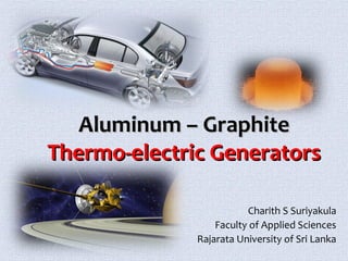
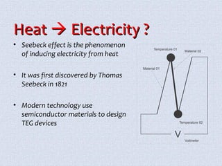
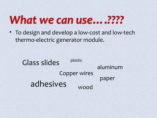
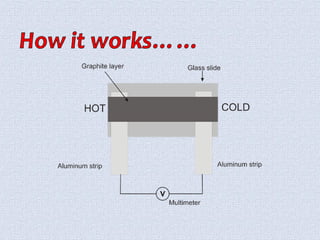
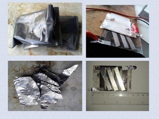
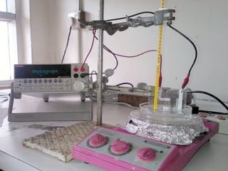
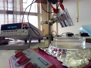
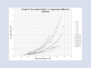
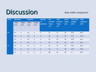
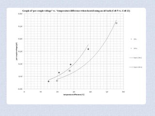
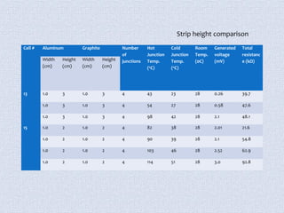
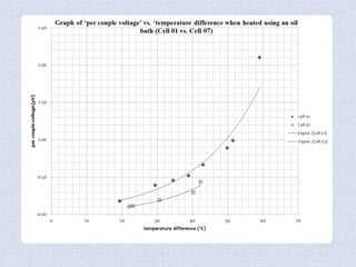
The document describes the design and testing of a simple and low-cost thermoelectric generator made of aluminum and graphite strips. The generator is based on the Seebeck effect to convert heat directly into electricity. Testing showed that increasing the temperature difference between the hot and cold junctions and the number of couples increased the generated voltage. Wider and taller strips also led to higher voltages. Future work could introduce better cooling and new materials to minimize heat transfer and make the design more portable.


![射頻電子 - [實驗第一章] 基頻放大器設計](https://cdn.slidesharecdn.com/ss_thumbnails/e1-150613065108-lva1-app6892-thumbnail.jpg?width=640&height=640&fit=bounds)